Nissan Rogue (T33) 2021-Present Service Manual: Egr System
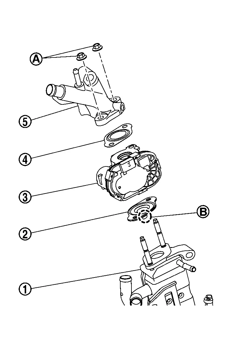
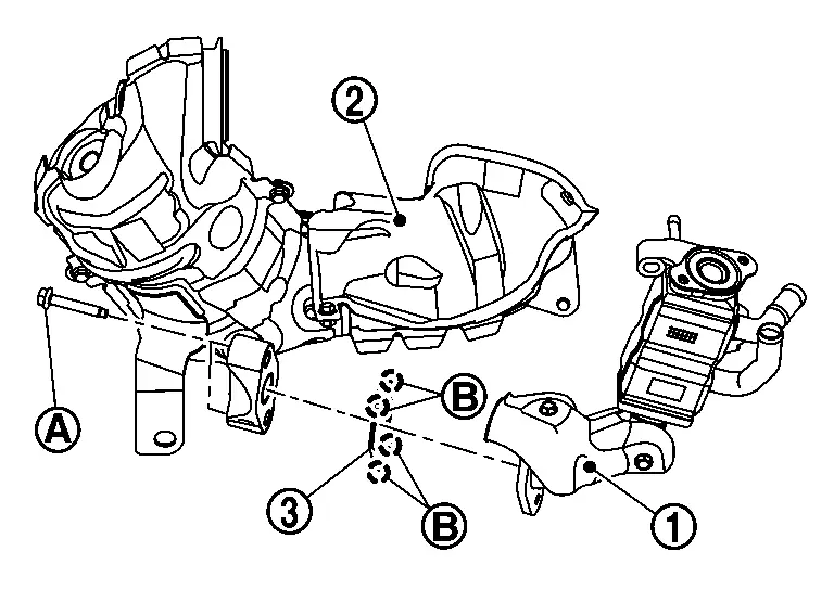
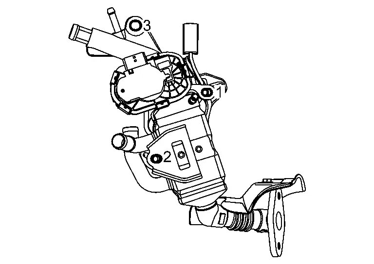
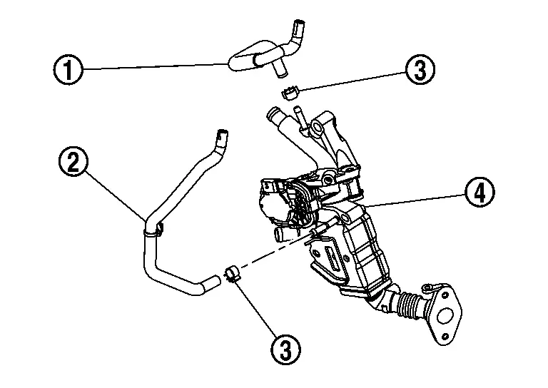
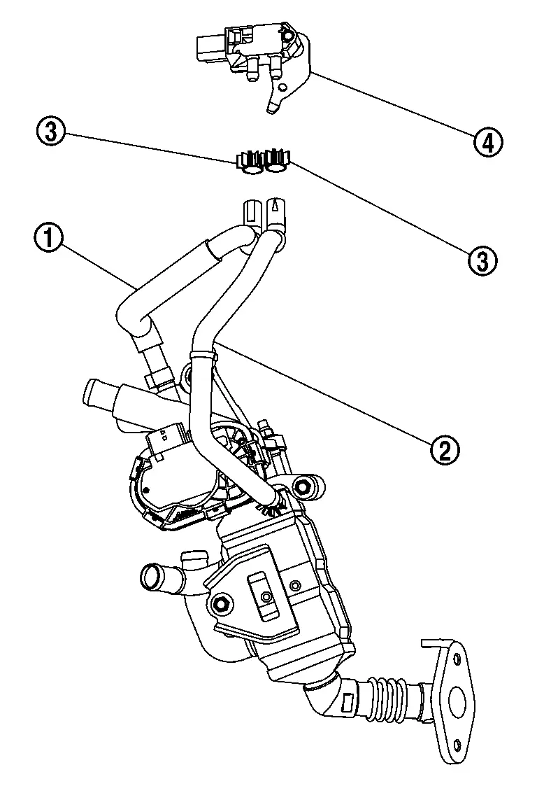
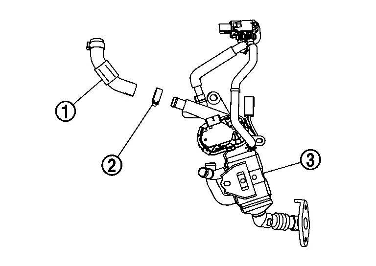
Exploded View
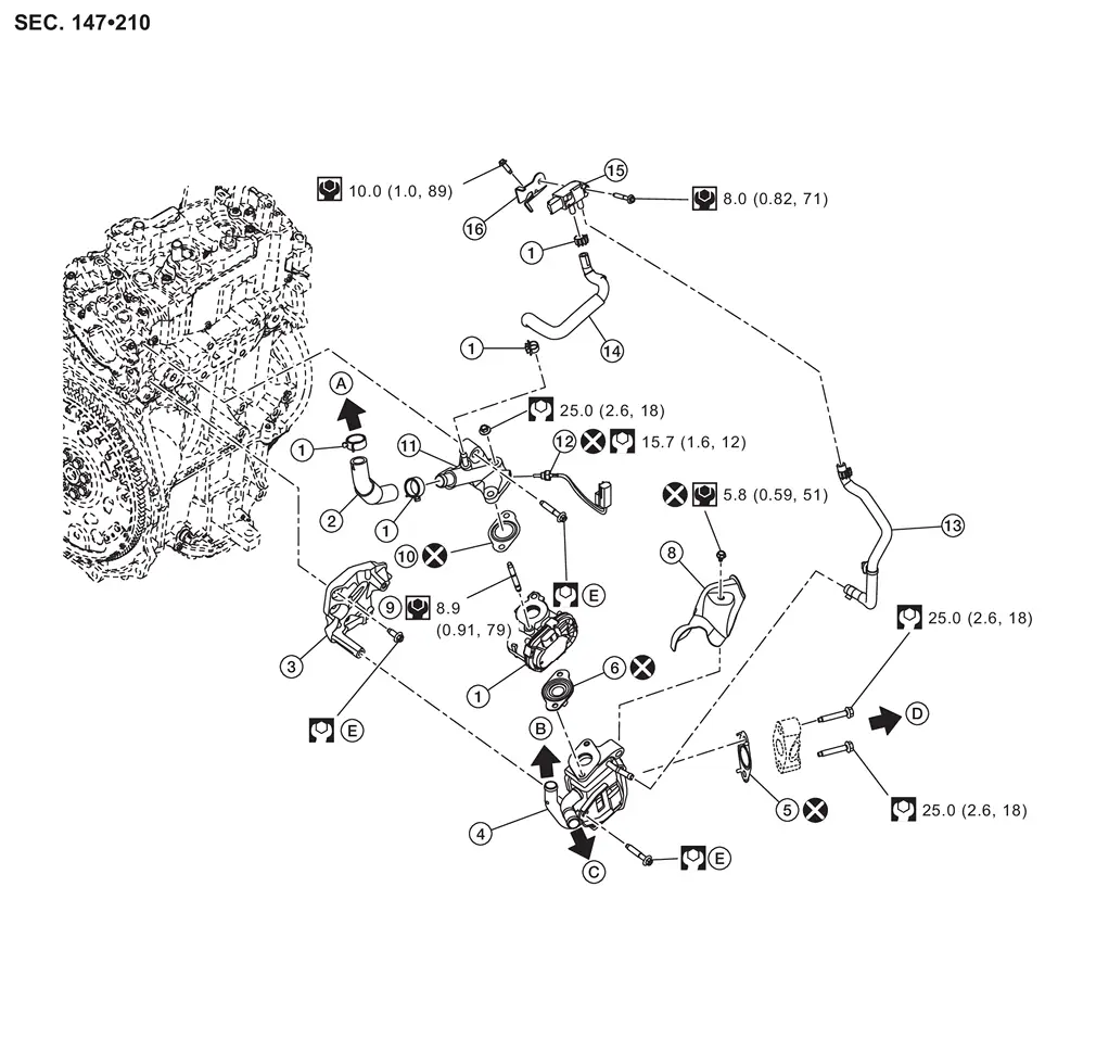
| 1. | Clamp | 2. | Back pressure hose | 3. | EGR valve spacer 1 |
| 4. | EGR cooler | 5. | EGR sub assembly gasket | 6. | EGR cooler gasket 1 |
| 7. | EGR volume control valve | 8. | EGR heat shield | 9. | Stud bolt |
| 10. | EGR cooler gasket 2 | 11. | EGR valve spacer 2 | 12. | EGR gas temperature sensor |
| 13. | Vacuum hose 1 | 14. | Vacuum hose 2 | 15. | EGR differential pressure sensor |
| 16. | Pressure sensor bracket | ŌĆö | ŌĆö | ŌĆö | ŌĆö |
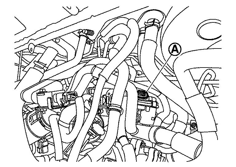
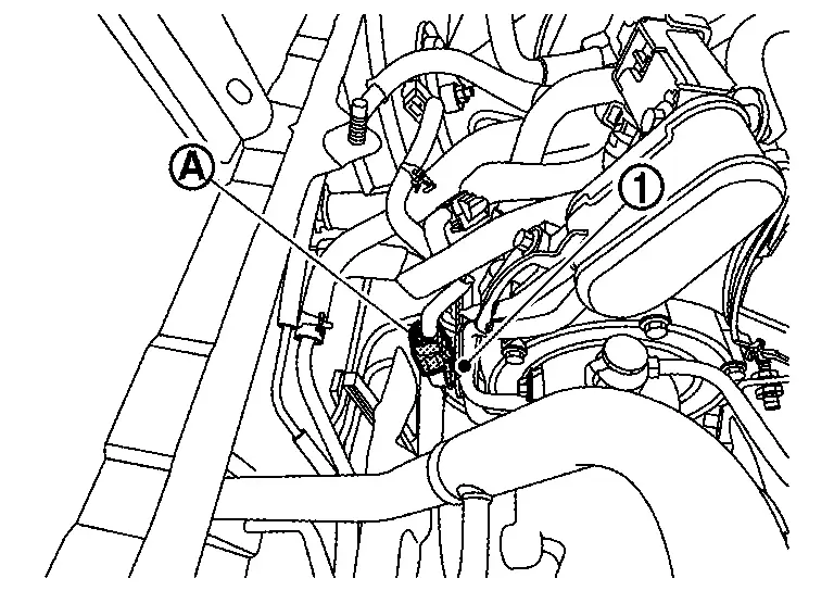
| A | To air duct. Refer to Exploded View. | B | To water hose 10. Refer to Exploded View. | C | To water hose 7. Refer to Exploded View. |
| D | To exhaust manifold and three way catalyst assembly. Refer to Exploded View. | E | Comply with assembly procedure when tightening. Refer to Removal and Installation. | ŌĆö | ŌĆö |
 |
: N┬Ęm (kg-m, ft-lb) | ||||
 |
: N┬Ęm (kg-m, in-lb) | ||||
 |
: Always replace after every disassembly. | ||||
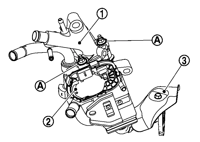
Removal and Installation
REMOVAL
Remove air duct. Refer to Removal and Installation.
Remove three way catalyst. Refer to Removal and Installation.
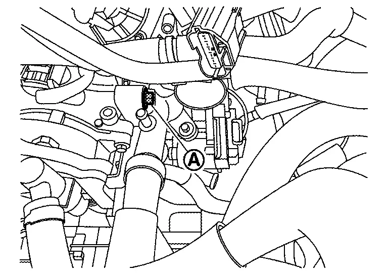
Disconnect EGR volume control valve harness connector  .
.
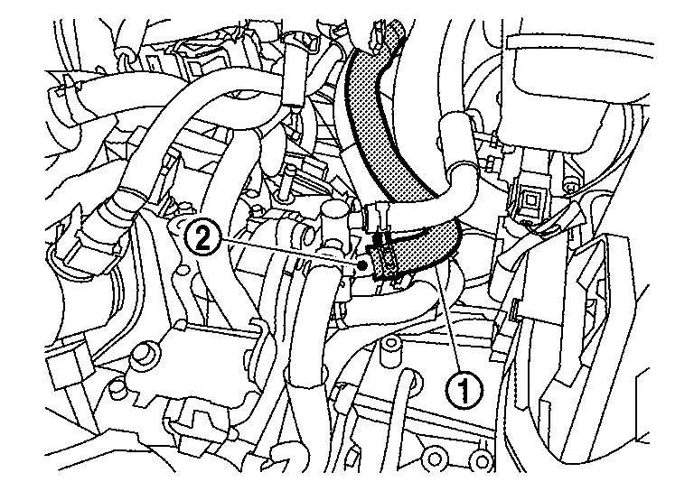
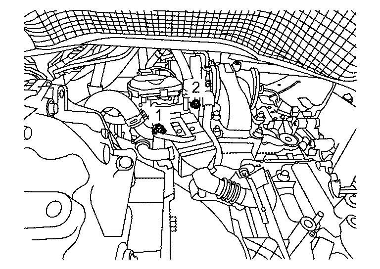
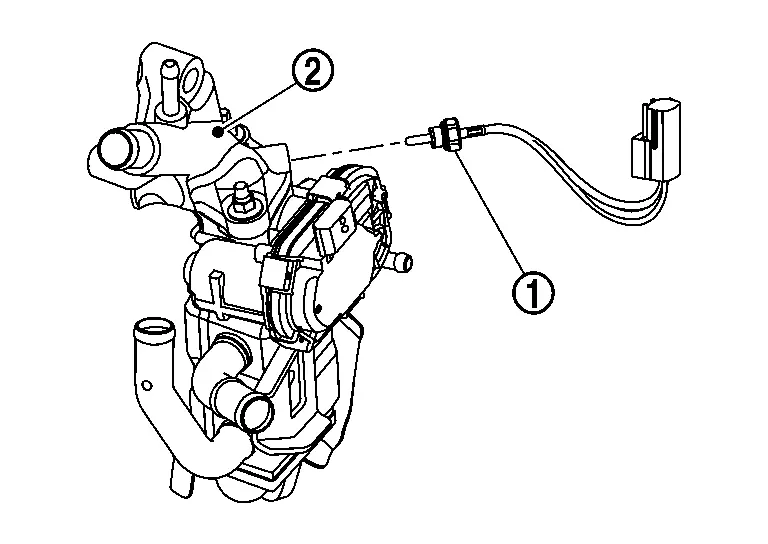
Disconnect EGR gas temperature sensor harness connector , and remove EGR temperature sensor harness connector from water pipe bracket  .
.
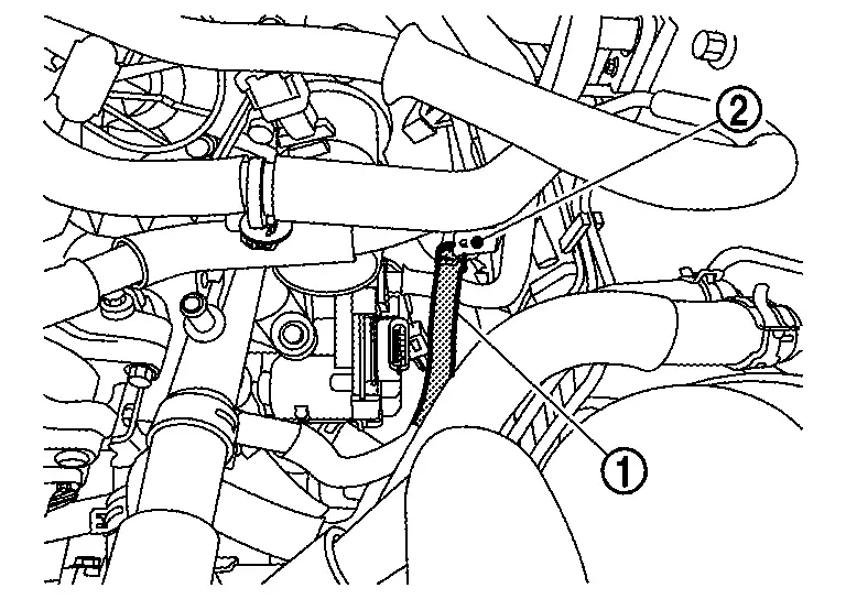
Remove back pressure hose .
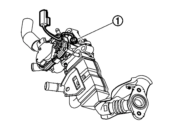
Disconnect vacuum hose 2 from EGR valve spacer 2  .
.

Disconnect water hose from water pipe bracket .
Disconnect heater hose from EGR cooler .
Disconnect water hose from EGR cooler .
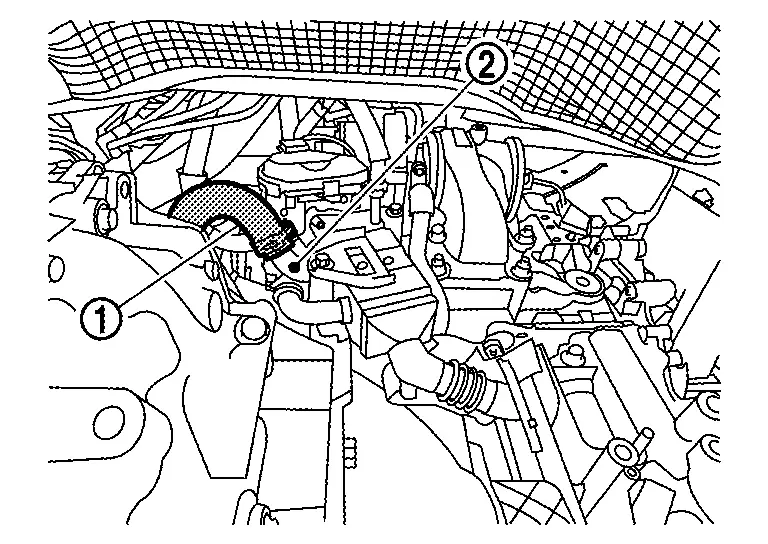
Disconnect vacuum hose 1 from EGR cooler .
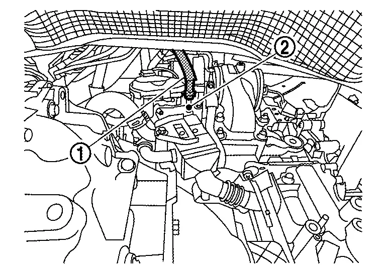
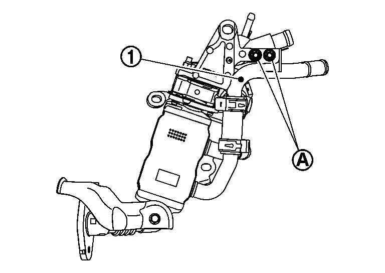
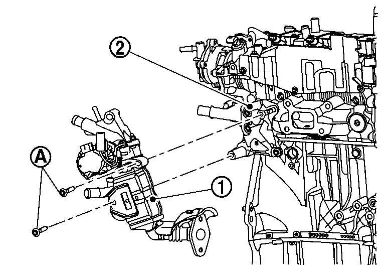
Remove EGR valve spacer 2 mounting bolt .
Loosen the EGR cooler mounting bolts of the sequence shown and remove.
Remove EGR cooler assembly from below the Nissan Ariya vehicle.
Remove EGR cooler bracket.
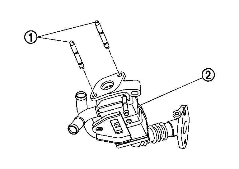
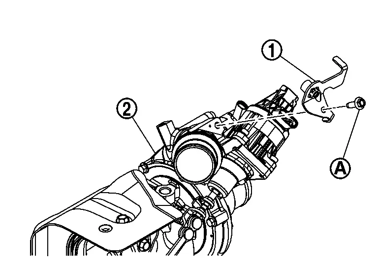
Remove EGR gas temperature sensor .
Remove bolts of water pipe .
Remove nuts and then remove EGR valve spacer 2 and EGR volume control valve .
 |
: EGR heat shield |
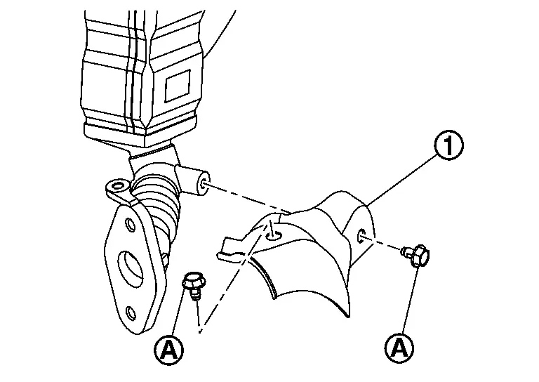
Remove EGR heat shield .
|
: EGR valve spacer 2 |
|
: EGR volume control valve |
|
: Nuts |
INSTALLATION
-
Note the following and install in the reverse order of removal
-
If replacing EGR volume control valve, perform "EGR volume control valve closed position learning". Refer to Description.
Install the EGR valve spacer 1  tighten the bolts to the specified torque the sequence shown.
|
: 25.0 N┬Ęm (2.6 kg-m, 18 ft-lb) |
 |
: Engine front |
Tighten the stud bolt to the EGR cooler .
Install the EGR cooler gasket 1 , EGR volume control valve , EGR cooler gasket 2 and EGR volume control valve spacer  to EGR cooler 2 , tighten EGR volume control valve spacer nuts specified torque.
CAUTION:
Install the EGR cooler gasket 1 to set pawls  EGR cooler side.
Install the EGR heat shield , tighten EGR heat shield bolt specified torque.
Install the EGR gas temperature sensor to EGR volume control valve spacer 2 .
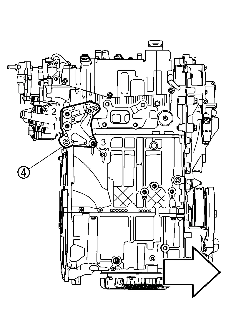
Install the EGR sub assembly to EGR valve spacer 1 and temporarily tighten the bolts .
Install the EGR sub assembly bolt to camshaft bracket .
Install the EGR sub assembly to three way catalyst assembly , tighten EGR sub assembly bolts to the specified torque.
CAUTION:
Install EGR sub assembly gasket to set pawls EGR sub assembly side.
Tighten the EGR sub assembly mounting bolts to the specified torque in the sequence shown.
|
: 25.0 N┬Ęm (2.6 kg-m, 18 ft-lb) |
Connect the EGR gas temperature sensor harness connector.
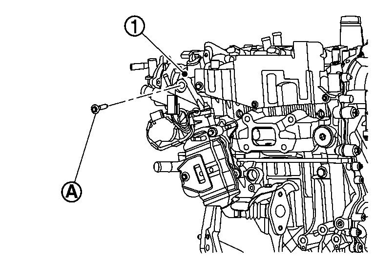
Install the pressure sensor bracket to turbocharger , tighten pressure sensor bracket bolt specified torque.
|
: 10.0 N┬Ęm (1.0 kg-m, 89 in-lb) |
Install the vacuum hose , vacuum hose and vacuum hose clamp to EGR sub assembly .
Install the vacuum hose , vacuum hose and vacuum hose clamp to exhaust gas pressure differential sensor .
Install the back pressure hose and hose clamp to EGR sub assembly .
Other materials:
Fuel Pump Control Module
Component Inspection
CHECK FUEL PUMP CONTROL MODULE (FPCM)
Check the voltage between FPCM terminals under the following conditions.
FPCM Condition
Voltage
(Approx.)
Connector + ŌłÆ
Terminal
B97
6
5
For 1 second after turning ignition switch ON
9.9 V
More than ...
Adp Branch Line Circuit
Diagnosis Procedure
CHECK CONNECTOR
Turn the ignition switch OFF.
Disconnect the battery cable from the negative terminal.
Check the following terminals and connectors for damage, bend and loose connection (unit side and connector side).
Driver seat control unit
Harness con ...
P2271 Ho2s2
DTC Description
The heated oxygen sensor 2 has a much longer switching time between
rich and lean than the air fuel ratio (A/F) sensor 1. The oxygen storage
capacity of the three way catalyst (manifold) causes the longer
switching time.
: 0.71 V
To judge the malfunctions of heated oxyge ...