Nissan Rogue (T33) 2021-Present Service Manual: Intake Manifold
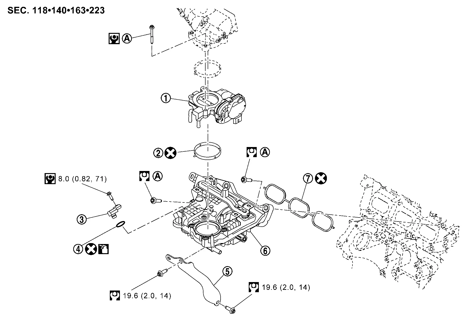
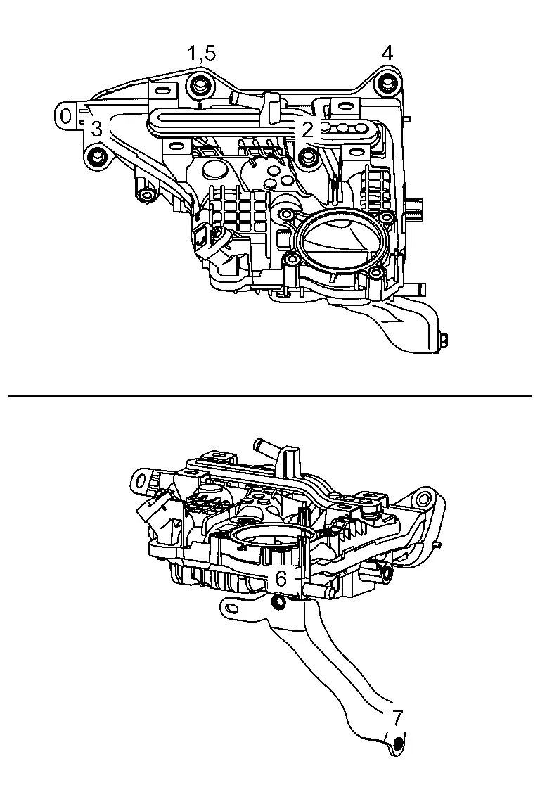
Exploded View
 |
Electric throttle control actuator |  |
Electric throttle control actuator gasket |  |
Manifold absolute pressure (MAP) sensor |
 |
O-ring |  |
Intake manifold support |  |
Intake manifold |
 |
Intake manifold gasket | ||||
 |
Comply with the assembly procedure when tightening. Refer to Removal and Installation. | ||||
 |
: Always replace after every disassembly. | ||||
 |
: N·m (kg-m, ft-lb) | ||||
 |
: N·m (kg-m, in-lb) | ||||
 |
: Should be lubricated with oil. | ||||
Removal and Installation
REMOVAL
WARNING:
To avoid the danger of being scalded, do not drain the coolant when the engine is hot.
 NOTE:
NOTE:
When removing components such as hoses, tubes/lines, etc., cap or plug openings to prevent fluid from spilling.
Remove charge air cooler. Refer to Removal and Installation.
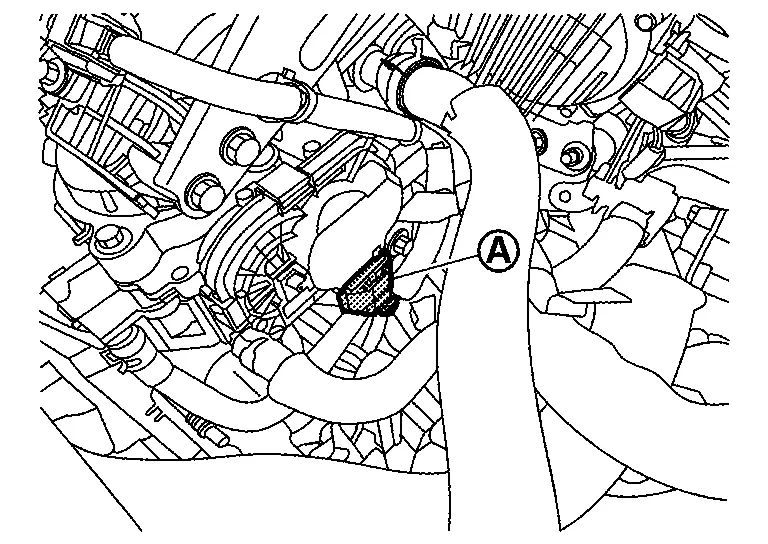
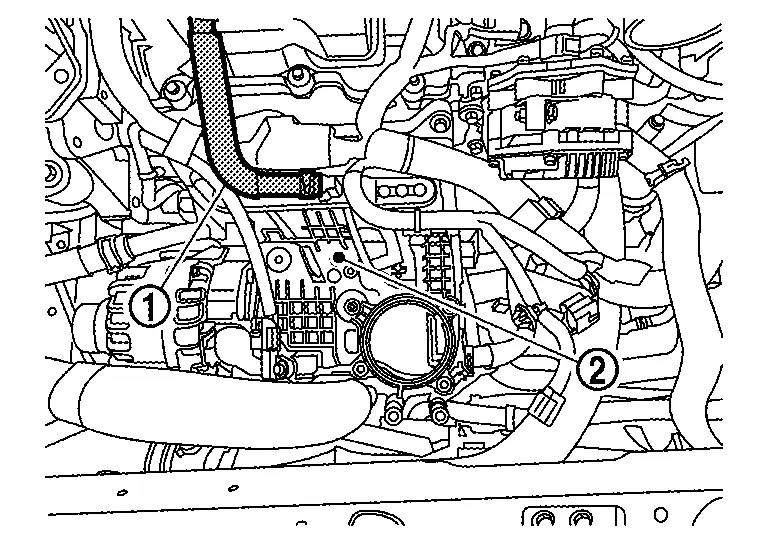
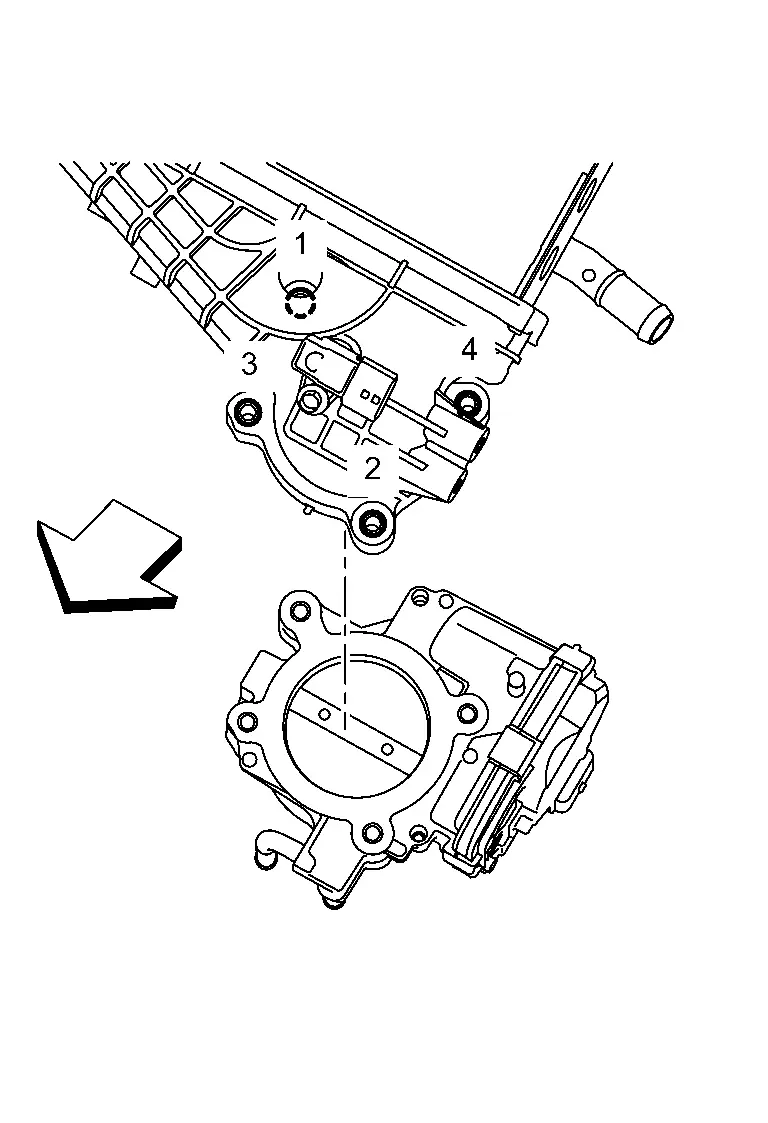
Disconnect electric throttle control actuator harness connector (A).
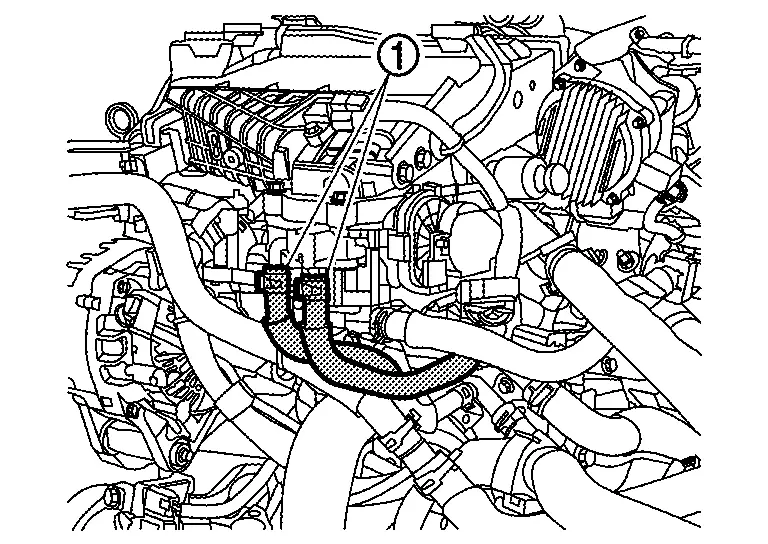
Disconnect water hose (1) from electric throttle control actuator, and remove electric throttle control actuator.
-
Drain engine coolant from radiator or attach plug to prevent engine coolant leakage when engine coolant is not drained. Refer to Draining.
CAUTION:
Perform this step when the engine is cold.
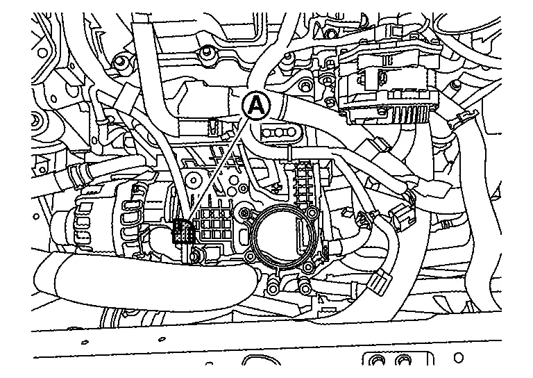
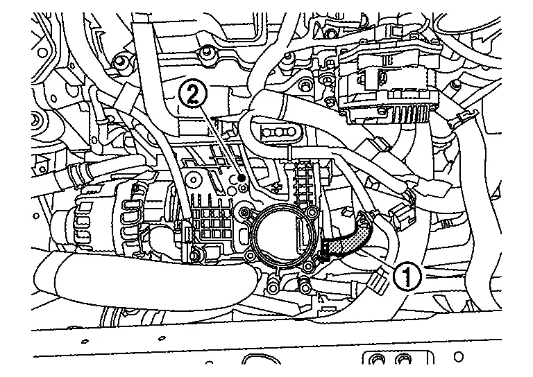
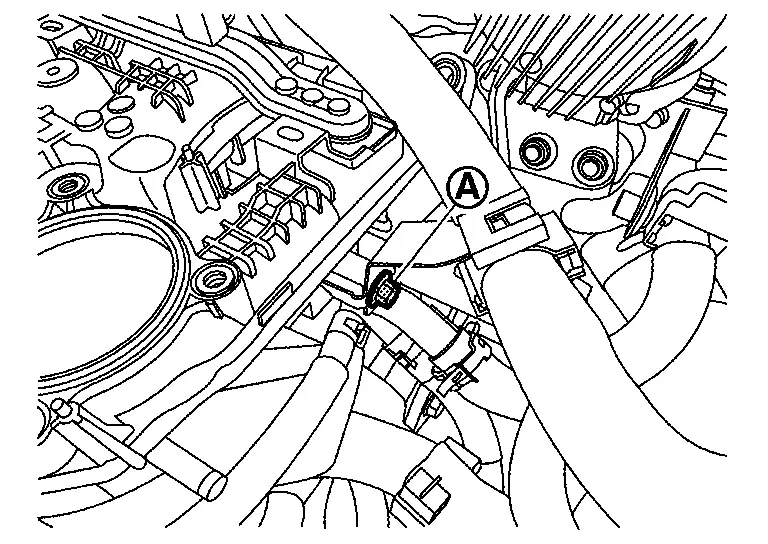
Disconnect manifold absolute pressure (MAP) sensor harness connector (A).
Disconnect PCV hose (1) from intake manifold (2).
For models without ProPILOT Assist 2.1, disconnect vacuum hose (1) from intake manifold (2).
Remove water pipe bracket bolt (A).
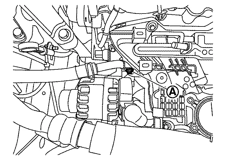
Remove engine harness bracket bolt (A).
Disconnect engine harness clips on the intake manifold.
Loosen nuts and bolts in reverse of the sequence shown and remove the intake manifold.
CAUTION:
-
Do not reuse intake manifold gasket.
-
Cover engine openings to prevent entry of foreign materials.
NOTE:
Disregard No. 5 when loosening
INSTALLATION
Note the following and install in the reverse order of removal.
-
Add engine coolant if necessary. Refer to Refilling.
Intake Manifold
Securely install intake manifold gasket to the mounting groove.
CAUTION:
Do not reuse intake manifold gasket.
Install and tighten intake manifold nuts and bolts using the following procedure:
CAUTION:
Do not reuse intake manifold gasket.
Hand tighten bolts. Tighten intake manifold bolts to the specified torque in the sequence shown.
| Intake manifold bolts |
: 25.0 N·m (2.6 kg-m, 18 ft-lb) |
Installation is in the reverse order of removal.
Electric Throttle Control Actuator
Install a new gasket on the electric throttle control actuator.
CAUTION:
Do not reuse electric throttle control actuator gasket.
Tighten the bolts of electric throttle control actuator in numerical order as shown.
|
: 10.0 N·m (1.0 kg-m, 89 in-lb) |
| : Nissan Ariya Vehicle front |
CAUTION:
-
Do not reuse O-ring.
-
If electric throttle control actuator removed or replaced, perform "THROTTLE VALVE CLOSED POSITION LEARNING". Refer to Description.
-
If electric throttle control actuator replaced, perform "IDLE AIR VOLUME LEARNING". Refer to Description.
-
If electric throttle control actuator replaced, perform "AIR FUEL RATIO INITIAL LEARNING". Refer to Description.
Inspection
INSPECTION AFTER REMOVAL
Surface Distortion
-
Check the surface distortion of the intake manifold mating surfacewith a straightedge (B) and a feeler gauge (A).
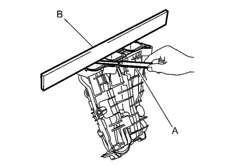
Limit : Refer to Intake Manifold. -
If it exceeds the limit, replace intake manifold.
Other materials:
Component Parts
Brake Control System
Component Parts Location
A.
Engine Room (LH Side)
No. Component Function
1.
Steering angle sensor
Refer to Steering Angle Sensor.
2.
Combination Meter
Refer to Component Parts Location (Type A Meter) or Component Parts Location (Type B Meter) f ...
Installing top tether strap
WARNING
Child restraint anchorages are designed only for correctly installed restraints. Never attach adult seat belts or other equipment to these points—doing so may damage the anchors and compromise safety.
Avoid hooking the tether strap on the seatback carpet. Always use the designated ...
Dtc/circuit Diagnosis. B2906-11 Recliner Sensor
DTC Description
DTC DETECTION LOGIC DTC No.
CONSULT screen items
(Trouble diagnosis content) DTC detection condition
B2906-11
Recliner Sensor
Diagnosis condition
The Recliner Sensor signal is shorted to ground
Signal (terminal)
Reclining Motor (terminal #5)
Threshold
...