Nissan Rogue (T33) 2021-Present Service Manual: Component Parts
Brake Control System
Component Parts Location
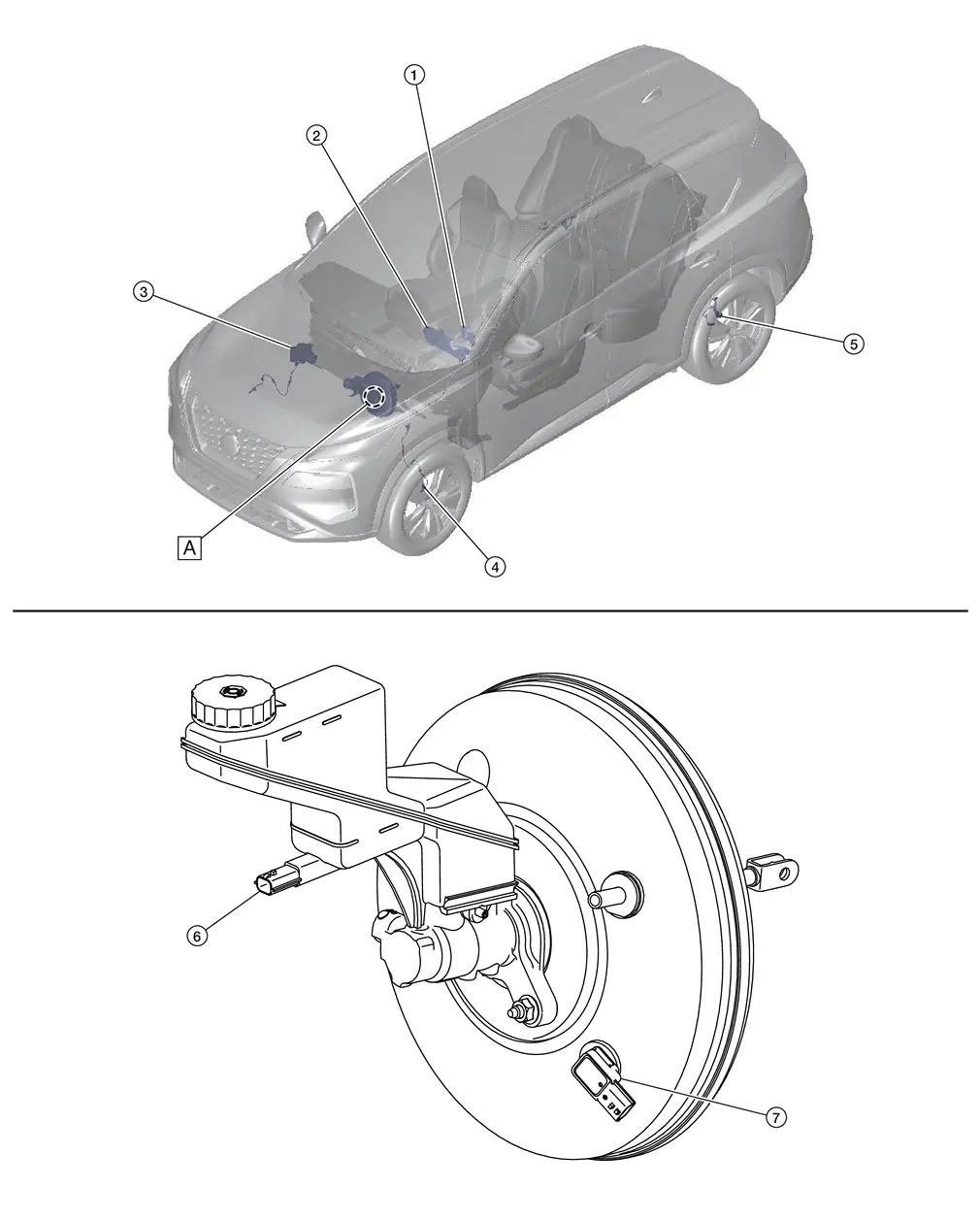
| A. | Engine Room (LH Side) |
| No. | Component | Function |
|---|---|---|
| 1. | Steering angle sensor | Refer to Steering Angle Sensor. |
| 2. | Combination Meter | Refer to Component Parts Location (Type A Meter) or Component Parts Location (Type B Meter) for detailed component location. |
| 3. | ABS (Anti-lock Braking System) Actuator and Electric Unit (Control Unit) | Refer to ABS Actuator and Electric Unit (Control Unit). |
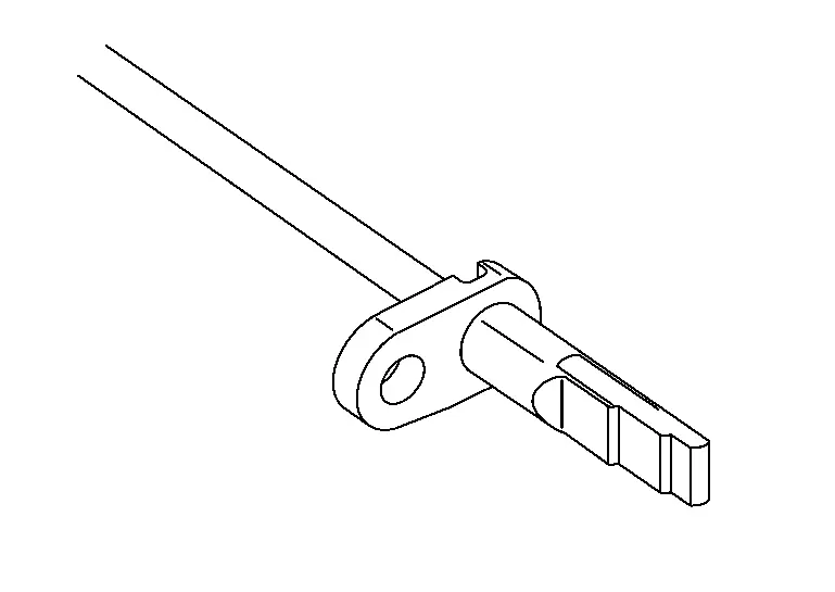
| 4. | Front Wheel Sensor LH (RH Similar) | Refer to Wheel Sensor and Sensor Rotor. |
| 5. | Rear Wheel Sensor LH (RH Similar) | Refer to Wheel Sensor and Sensor Rotor. |
| 6. | Brake Fluid Level Switch | Refer to Brake Fluid Level Switch. |
| 7. | Brake Vacuum Sensor | Refer to Brake Vacuum Sensor. |
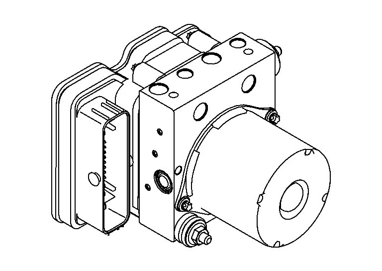
ABS Actuator and Electric Unit (Control Unit)
FUNCTIONS WITHIN THE SYSTEM
Electric unit (control unit) is integrated with actuator and comprehensively controls VDC function, TCS function, ABS function, EBD function, Brake limited slip differential (BLSD) function, Brake assist function, bake force distribution function, hill start assist function and electric parking brake function.
INDIVIDUAL FUNCTIONS WITHIN THE SYSTEM
ELECTRIC UNIT (CONTROL UNIT)
-
Brake fluid pressure, engine and transaxle are controlled according to signals from each sensor.
-
If malfunction is detected, the system enters fail-safe mode.
ACTUATOR
The following components are integrated with ABS actuator.
Pump
-
Pressurizes brake fluid in the master cylinder.
-
Returns the brake fluid to the reservoir of the master cylinder by reducing pressure.
Motor
Activates the pump according to signals from ABS actuator and electric unit (control unit).
Motor Relay
Operates the motor ON/OFF according to signals from ABS actuator and electric unit (control unit).
Actuator Relay
Operates each valve ON/OFF according to signals from ABS actuator and electric unit (control unit).
ABS In Valve
Switches the fluid pressure line to increase or hold according to signals from control unit.
 NOTE:
NOTE:
Valve is a solenoid valve.
ABS Out Valve
Switches the fluid pressure line to increase, hold or decrease according to signals from control unit.
NOTE:
Valve is a solenoid valve.
Cut Valve 1, Cut Valve 2
Shuts off the ordinary brake line from master cylinder, when VDC function, TCS function, brake limited slip differential (BLSD) function, brake assist function, brake force distribution function, and hill start assist function are activated.
NOTE:
Valve is a solenoid valve.
Suction Valve 1, Suction Valve 2
Supplies the brake fluid from master cylinder to the pump, when VDC function, TCS function, brake limited slip differential (BLSD) function, brake assist function, brake force distribution function, and hill start assist function are activated.
NOTE:
Valve is a solenoid valve.
Inlet Valve
Brake fluid sucked from the reservoir by the pump does not backflow.
NOTE:
Valve is a solenoid valve.
Outlet Valve
Brake fluid discharged from the pump does not backflow.
NOTE:
Valve is a solenoid valve.
Return Check Valve
Returns the brake fluid from brake caliper to master cylinder by bypassing orifice of each valve when brake is released.
Reservoir
Temporarily reserves the brake fluid drained from brake caliper and wheel cylinder, so that pressure efficiently decreases when decreasing pressure of brake caliper.
Yaw Rate/Side/Decel G Sensor
Calculates the following information that affects the vehicle, and transmits a signal to ABS actuator and electric unit (control unit) via communication lines. [Yaw rate/side/decel G sensor is integrated in ABS actuator and electric unit (control unit).]
-
Vehicle rotation angular velocity (yaw rate signal)
-
Vehicle lateral acceleration (side G signal) and longitudinal acceleration (decel G signal)
Pressure Sensor
Detects the brake fluid pressure and transmits signal to ABS actuator and electric unit (control unit). [Pressure sensor is integrated in ABS actuator and electric unit (control unit).]
INDIVIDUAL OPERATION
-
Brake fluid pressure, and traction motor are controlled according to signals from each sensor.
-
If malfunction is detected, the system enters fail-safe mode.
PARTS LOCATION
Refer to Component Parts Location.
Wheel Sensor and Sensor Rotor
FUNCTIONS WITHIN THE SYSTEM
Wheel sensor and sensor rotor detect each wheel speed. And wheel sensor inputs wheel speed signal to ABS actuator and electric unit (control unit).
INDIVIDUAL FUNCTIONS WITHIN THE SYSTEM
The wheel sensor reads a magnetic field change.
INDIVIDUAL OPERATION
-
Downsize and weight reduction is aimed. IC for detection portion and magnet for sensor rotor are adopted.
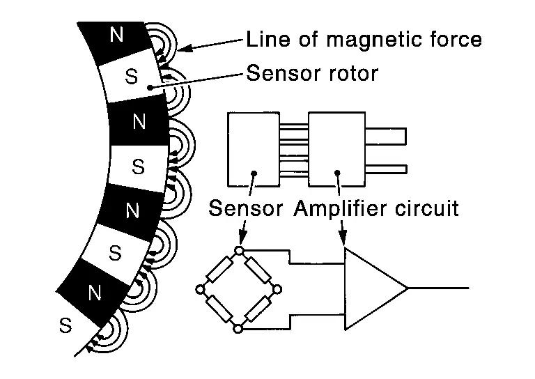
-
Power supply is supplied to detection portion so that magnetic field line is read. Magnetic field that is detected is converted to current signal.
-
When sensor rotor rotates, magnetic field changes. Magnetic field change is converted to current signals (rectangular wave) and is transmitted to ABS actuator and electric unit (control unit). Change of magnetic field is proportional to wheel speed.
PARTS LOCATION
Refer to Component Parts Location.
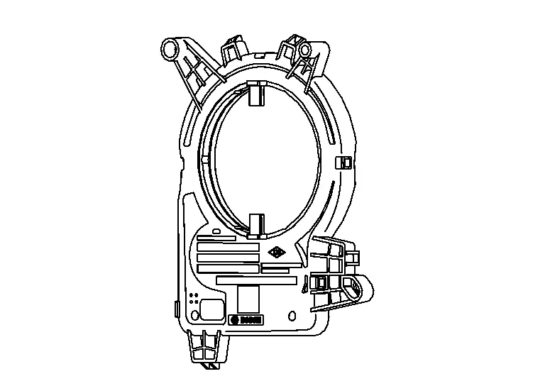
Steering Angle Sensor
FUNCTIONS WITHIN THE SYSTEM
Steering angle sensor transmits steering angle sensor signal to ABS actuator and electric unit (control unit) via CAN communication.
INDIVIDUAL FUNCTIONS WITHIN THE SYSTEM
Steering angle sensor detects the following status.
-
Steering wheel rotation amount
-
Steering wheel rotation angular velocity
-
Steering wheel rotation direction
INDIVIDUAL OPERATION
Steering angle sensor converts the rotation amount, rotation angular velocity and rotation direction of the steering wheel as the steering angle sensor signal.
PARTS LOCATION
Refer to Component Parts Location.
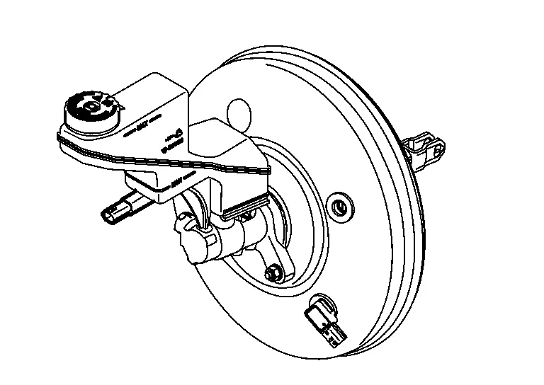
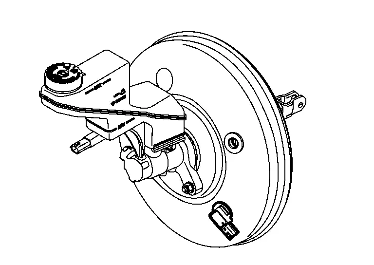
Brake Fluid Level Switch
FUNCTIONS WITHIN THE SYSTEM
Detects the brake fluid level in reservoir tank and transmits converted electric signal from combination meter to ABS actuator and electric unit (control unit) via CAN communication, when brake fluid level is the specified level or less.
INDIVIDUAL FUNCTIONS WITHIN THE SYSTEM
Brake fluid level switch detects the brake fluid level in reservoir tank.
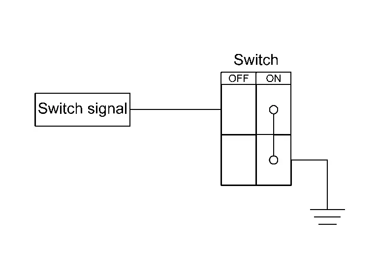
INDIVIDUAL OPERATION
-
The switch is turned ON when brake fluid level is the specified level or less.
-
Ground is supplied as the switch signal to the control unit when the switch is ON.
PARTS LOCATION
Refer to Component Parts Location.
Brake Vacuum Sensor
FUNCTIONS WITHIN THE SYSTEM
Detects the vacuum in brake booster and transmits converted electric signal to ABS actuator and electric unit (control unit).
INDIVIDUAL FUNCTIONS WITHIN THE SYSTEM
Detects the vacuum in brake booster.
INDIVIDUAL OPERATION
Brake vacuum sensor converts the brake vacuum sensor signal.
PARTS LOCATION
Refer to Component Parts Location.
Other materials:
Removal and Installation. Inside Key Antenna
Japan Production Models
Removal and Installation
REMOVALRemove luggage rear plate. Refer to Removal and Installation.
Remove inside key antenna fixing clips , and then remove inside key antenna .
INSTALLATIONNote the following items, and then install in the reverse order of removal.CAUTION:
N ...
Dtc/circuit Diagnosis. U2141-87 Can Comm Err (tcm)
DTC Description
DESCRIPTIONCAN (Controller Area Network) is a serial
communication line for real time applications. It is an on-Nissan Ariya
vehicle multiplex communication line with high data communication speed
and excellent error detection ability. Modern Nissan Ariya vehicle is
equipped ...
2wd. Preparation. Preparation
Preparation
Special Service Tool
Tool number
(TechMate No.)
Tool name Description
KV40104000
( – )
Hub lock nut wrench
a: 85 mm (3.35 in)
b: 65 mm (2.56 in)
Removing and Installing wheel hub lock nut.
KV40107300
( – )
Boot band crimping tool
Installing bo ...