Nissan Rogue (T33) 2021-Present Service Manual: System Description :: System. Sonar System
Sonar System
System Description
SYSTEM DIAGRAM
With 8" Color Display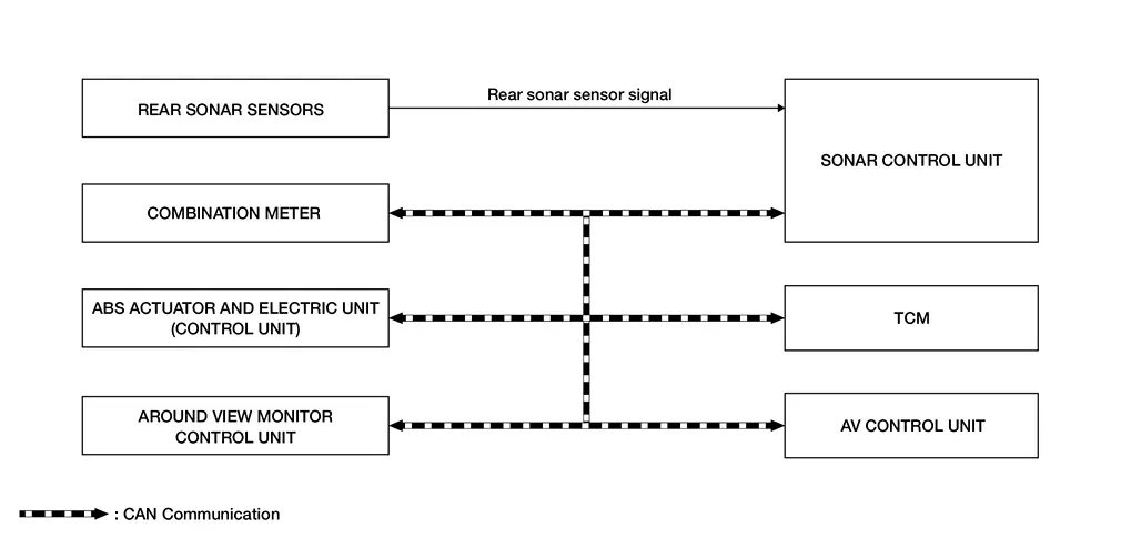
With 12.3" Color Display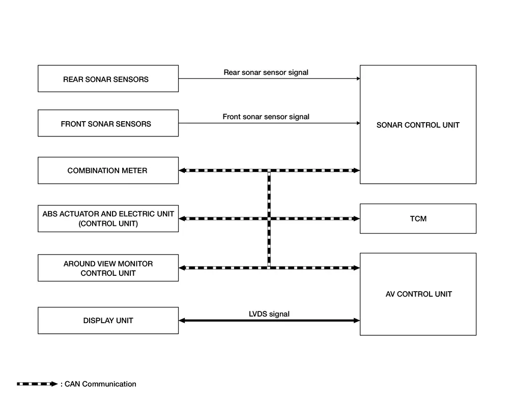
Sonar Control Unit Input Signal (CAN Communication)
| Transmit unit | Signal name |
|---|---|
| Combination meter | System selection signal |
| ABS actuator and electric unit (control unit) | Nissan Ariya Vehicle speed signal |
| TCM | Shift position signal |
Sonar Control Unit Output Signal (CAN Communication)
| Receive unit | Signal name |
|---|---|
| Combination meter |
|
| AV control unit | Sonar indicator signal |
| Around view monitor control unit | Sonar indicator signal |
DESCRIPTION
-
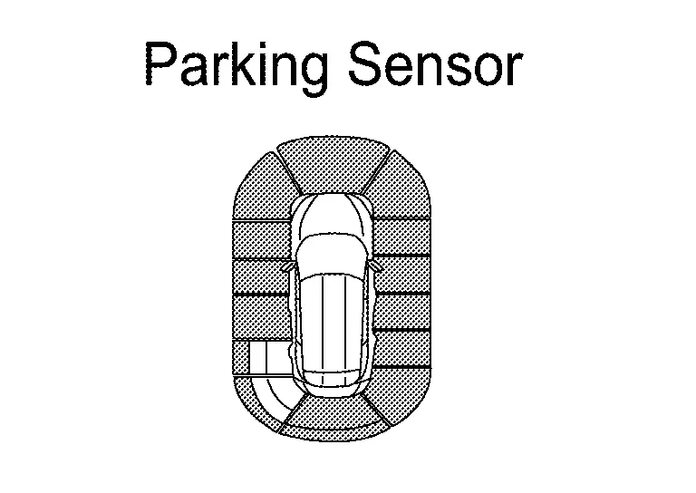
The sonar sensors installed in the front bumper and rear bumpers detect obstacles around the bumpers.
-
The sonar control unit changes the buzzer cycle and warning indicator according to the distance from an obstacle detected by the sonar sensors.
SONAR SYSTEM ACTIVATION CONDITION
The sonar system warns the driver of the presence of obstacles when the following conditions are met.
Ă—: Activation
| Shift position | Nissan Ariya Vehicle speed (Approx.) | Obstacle detecting sensor | Buzzer | Sonar indicator |
|---|---|---|---|---|
| R | 10 km/h (6.21MPH) or less | Front sensor | Ă— | Ă— |
| Rear sensor | Ă— | Ă— | ||
| D | 10 km/h (6.21MPH) or less | Front sensor | Ă— | Ă— |
| Rear sensor | — | — |
Ă—: Activation
| Shift position | Nissan Ariya Vehicle speed (Approx.) | Obstacle detecting sensor | Buzzer | Sonar indicator |
|---|---|---|---|---|
| R | 10 km/h (6.21MPH) or less | Front sensor | — | × |
| Rear sensor | Ă— | Ă— | ||
| D | 10 km/h (6.21MPH) or less | Front sensor | Ă— | Ă— |
| Rear sensor | — | — |
OBSTACLE DETECTION DISTANCE
Warning Buzzer Frequency
-
The warning buzzer output frequency changes in 4 levels according to the detection distance.
-
As the Nissan Ariya vehicle approaches an obstacle, the buzzer-sounding cycle becomes shorter.
-
4 Sensor Models
Obstacle detection range image
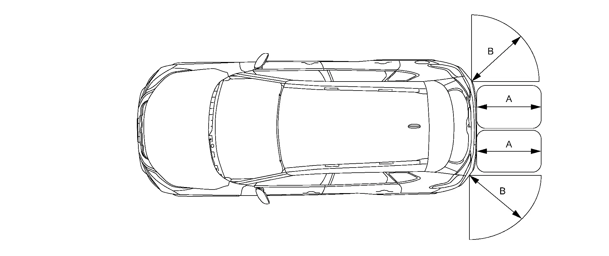
A. Approx. 150 cm (59.06 in)
(default value)B. Approx. 60 cm (23.62 in)
(default value) -
8 Sensor Models
Obstacle detection range image
A. Approx. 120 cm (47.24 in)
(default value)B. Approx. 60 cm (23.62 in)
(default value) -
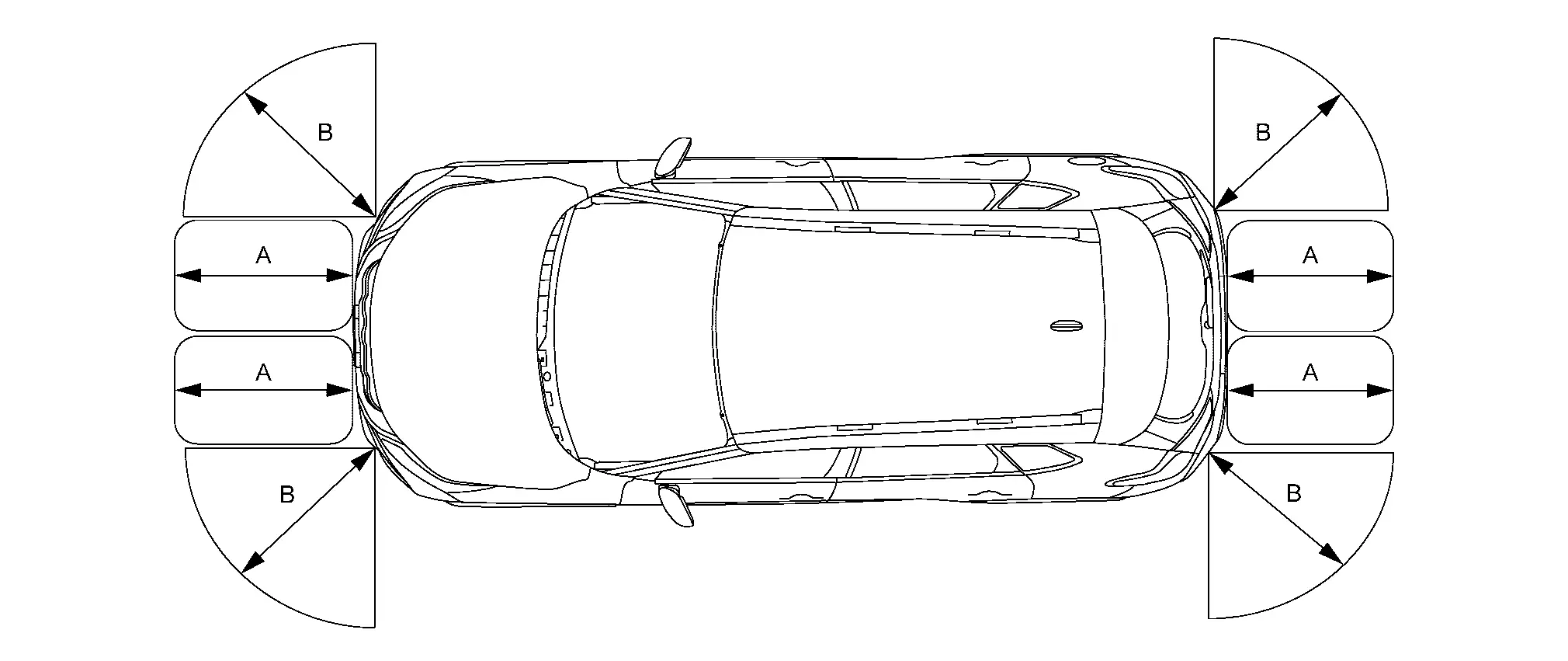
10 Sensor Models
Obstacle detection range image
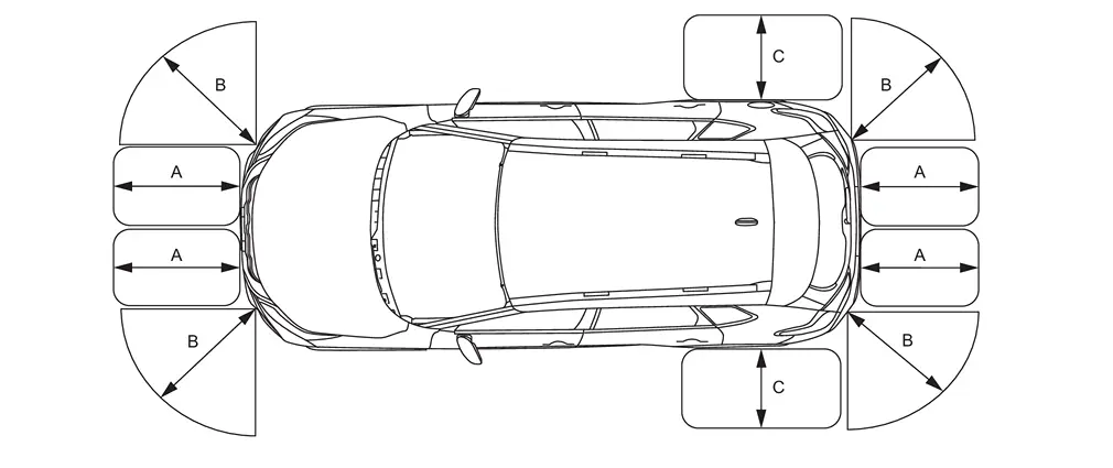
A. Approx. 150 cm (59.06 in)
(default value)B. Approx. 60 cm (23.62 in)
(default value)C. Approx. 60 cm (23.62 in)
(default value)
| Detection distance | Warning buzzer frequency |
|---|---|
|
30 - 35 cm (11.81 - 13.78 in) |
10.0 Hz |
|
35 - 50 cm (13.78 - 19.69 in) |
9.0 Hz |
|
50 - 70 cm (19.69 - 27.56 in) |
6.66 Hz |
|
70 - 90 cm (27.56 - 35.43 in) |
5.0 Hz |
|
90 - 120 cm (35.43 - 47.24 in) |
4.0 Hz |
|
120 - 150 cm (47.24 - 59.06 in) |
3.0 Hz |
|
150 - 180 cm (59.06 - 70.87 in) |
2.5 Hz |
|
180 cm or more (70.87 in or more) |
2.0 Hz |
-
Detection distance of an obstacle changes as shown in the table below.
Detection distance Item (detection range) Outer sensor Side sensor Front inner sensor Rear inner sensor FAR Approx. 66 cm (25.98 in) Approx. 66 cm (25.98 in) Approx. 110 cm (43.31 in) Approx. 165 cm (64.96 in) NORMAL (default value) Approx. 60 cm (23.62 in) Approx. 60 cm (23.62 in) Approx. 100 cm (39.37 in) Approx. 150 cm (59.06 in) NEAR Approx. 54 cm (21.26 in) Approx. 54 cm (21.26 in) Approx. 90 cm (35.43 in) Approx. 135 cm (53.15 in)
Sonar Indicator
-
The sonar indicator displays in three stages (green, yellow, and red), according to a distance from an obstacle.
-
Sonar indicator distance display changes according to the following table.
Status of warning Detection distance Outer sensor Side sensor Front inner sensor Rear inner sensor Red 0 - 30 cm
(0 - 11.81 in)0 - 30 cm
(0 - 11.81 in)0 - 30 cm
(0 - 11.81 in)0 - 30 cm
(0 - 11.81 in)Yellow 31 - 50 cm
(12.2 - 19.69 in)31 - 50 cm
(12.2 - 19.69 in)31 - 60 cm
(12.2 - 23.62 in)31 - 60 cm
(12.2 - 23.62 in)Green 51 - 60 cm
(20.08 - 23.62 in)51 - 60 cm
(20.08 - 23.62 in)61 - 100 cm
(24.02 - 39.37 in)61 - 150 cm
(24.02 - 59.06 in)
MAC (Message Authentication Code)
MAC (Message Authentication Code) is a function that prevents unauthorized communication by using secure authentication communication. Sonar control unit writes a MAC key required for communication between ECUs and performs MAC diagnosis.
Other materials:
P11b0 Vcr Target Angle (cold Start)
DTC Description
DTC DETECTION LOGIC DTC
CONSULT screen terms
(Trouble diagnosis content)
DTC detection condition
P11B0
00
VCR target angle (cold start)
[Variable compression ratio target angle (cold start)]
Diagnosis condition
Engine cold start
Signal (terminal)
â ...
Multi Remote Ent
CONSULT Function (BCM - MULTI REMOTE ENT)
DATA MONITORNOTE:
The following table includes information (items)
inapplicable to this Nissan Ariya vehicle. For information (items)
applicable to this vehicle, refer to CONSULT display items.
Monitor Item Condition
Stop/start switch
[On/Off] ...
Can Fundamental. Trouble Diagnosis
Component Description
System Description
Component Description
Main line
CAN communication line between splices
Branch line
CAN communication line between splice and a control unit
Splice
A point connecting a branch line with a main line
Termination circuit
Circuit ...