Nissan Rogue (T33) 2021-Present Service Manual: System Description :: Component Parts
Component Parts Location
With 8" Color Display
| No. | Component | Function |
|---|---|---|
| 1. | Rear sonar sensor RH inner | Refer to Sonar Sensor. |
| 2. | Rear sonar sensor RH outer | |
| 3. | Sonar control unit | Refer to Sonar Control Unit. |
| 4. | Around view monitor control unit | Receives the sonar indicator signal via CAN communication from the sonar control unit. |
| 5. | AV control unit | |
| 6. | ABS (Anti-lock Braking System) actuator and electric unit (control unit) | Provides the sonar control unit with the Nissan Ariya vehicle speed signal via CAN communication. |
| 7. | TCM (Transmission Control Module) | Provides the sonar control unit with the shift position signal via CAN communication. |
| 8. | Combination meter |
|
| 9. | Rear sonar sensor LH outer | Refer to Sonar Sensor. |
| 10. | Rear sonar sensor LH inner |
With 12.3" Color Display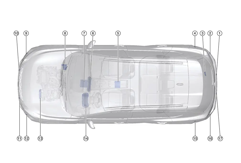
| No. | Component | Function |
|---|---|---|
| 1. | Rear sonar sensor RH inner | Refer to Sonar Sensor. |
| 2. | Rear sonar sensor RH outer | |
| 3. | Sonar control unit | Refer to Sonar Control Unit. |
| 4. | Rear sonar sensor RH side (with side sonar system) | Refer to Sonar Sensor. |
| 5. | Around view monitor control unit | Receives the sonar indicator signal via CAN communication from the sonar control unit. |
| 6. | Display unit | Displays the sonar indicator signal received from the AV control unit. |
| 7. | AV control unit | Receives the sonar indicator signal via CAN communication from the sonar control unit. |
| 8. | ABS (Anti-lock Braking System) actuator and electric unit (control unit) | Provides the sonar control unit with the Nissan Ariya vehicle speed signal via CAN communication. |
| 9. | Front sonar sensor RH outer (with front sonar system) | Refer to Sonar Sensor. |
| 10. | Front sonar sensor RH inner (with front sonar system) | |
| 11. | Front sonar sensor LH inner (with front sonar system) | |
| 12. | Front sonar sensor LH outer (with front sonar system) | |
| 13. | TCM (Transmission Control Module) | Provides the sonar control unit with the shift position signal via CAN communication. |
| 14. | Combination meter |
|
| 15. | Rear sonar sensor LH side (with side sonar system) | Refer to Sonar Sensor. |
| 16. | Rear sonar sensor LH outer | |
| 17. | Rear sonar sensor LH inner |
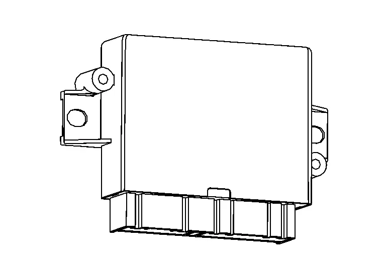
Sonar Control Unit
-
Sonar control unit is located in the luggage room under the luggage floor board.
-
Sonar control unit supplies power to each sonar sensor.
-
For vehicles with Intelligent Around View® Monitor system, sonar sensor signals are received by the sonar control unit and transmitted to the around view monitor control unit and combination meter via CAN communication for the indicator display.
-
For vehicles with rear view monitor system, sonar sensor signals are received by the sonar control unit and transmitted to the AV control unit and combination meter via CAN communication for the indicator display.
-
Sonar control unit outputs a buzzer signal to the AV control unit via CAN communication for the audible alert.
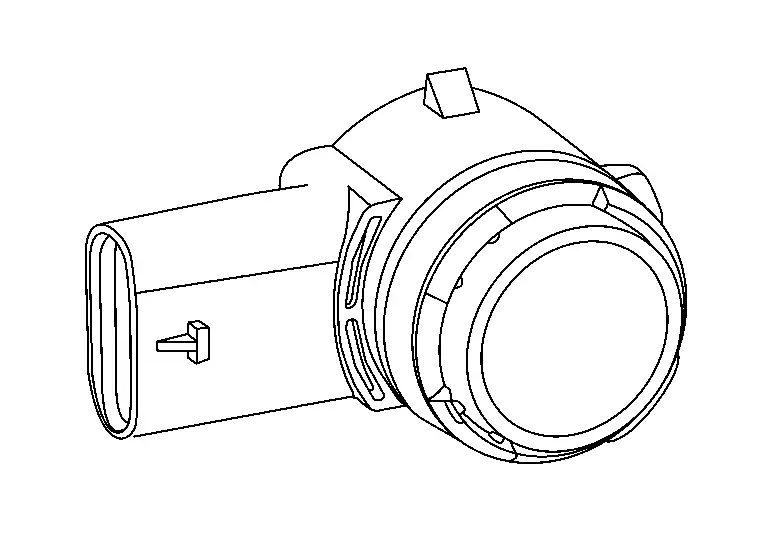
Sonar Sensor
-
Sonar sensors are located in the front and rear bumper fascias.
-
When a distance from an obstacle is detected, a signal is transmitted to the sonar control unit.
Other materials:
U2a8c-88 Ethernet Circuit
DTC Description
DTC DETECTION LOGIC DTC No. CONSULT screen terms DTC detected condition
U2A8C-88
Ethernet circuit
Diagnosis condition
When ignition switch is ON.
Signal (terminal)
—
Threshold
Lost ethernet communication with AV control unit
Diagnosis delay time ...
Dtc/circuit Diagnosis. B2426-12 Spindle Sensor Lh
DTC Description
DTC DETECTION LOGIC DTC No.
CONSULT screen items
(Trouble diagnosis content) DTC Detection Condition
B2426-12
Spindle sensor LH
(Spindle sensor left hand)
Diagnosis condition
When the door unlock operates while ignition switch is OFF (auto ACC OFF status) or the ba ...
B120e-55 Ipdm E/r
DTC Description
DTC DETECTION LOGIC DTC No.
CONSULT screen items
(Trouble diagnosis content) DTC detection condition
B120E-55
IPDM E/R
(Intelligent power distribution module engine room)
[NOT CONFIGURED]
Diagnosis condition
When ignition switch is ON
Signal (terminal)
â ...