Nissan Rogue (T33) 2021-Present Service Manual: System Description :: Component Parts. Srs Air Bag Control System
Srs Air Bag Control System
Component Parts Location
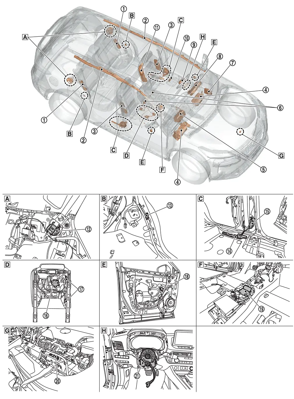
| 1. | Rear side air bag module | 2. | Curtain air bag module | 3. | Front side air bag module |
| 4. | Knee air bag module | 5. | Passenger air bag module | 6. | Front seat belt buckle switch |
| 7. |
BCM (Body Control Module) Refer to Component Parts Location for detailed component location. |
8. | Combination meter (SRS air bag warning lamp) | 9. | Driver air bag module |
| 10. | Front passenger air bag OFF indicator | 11. | Front center air bag module | 12. | Rear seat belt pre-tensioner |
| 13. | C-pillar satellite sensor | 14. | Lap pre-tensioner | 15. | Front seat belt pre-tensioner |
| 16. | Occupant detection system control unit | 17. | Occupant detection system sensor | 18. | Front door satellite sensor |
| 19. | Air bag diagnosis sensor unit | 20. | Crash zone sensor | 21. | Spiral cable |
| A | View with luggage side lower finisher removed | B | View with luggage side lower finisher removed | C | View with floor carpet removed |
| D | Backside of passenger seat cushion | E | View with front door finisher removed | F | View with center console assembly removed |
| G | View of radiator core support cover removed | H | View with steering wheel removed | — | — |
Other materials:
Dtc/circuit Diagnosis. B2416-15 Touch Sensor Circuit Rh Open
DTC Description
DTC DETECTION LOGIC DTC No.
CONSULT screen items
(Trouble diagnosis content) DTC Detection Condition
B2416-15
Touch sensor circuit RH open
(Touch sensor circuit right hand open)
Diagnosis condition
All times
Signal (terminal)
Touch sensor RH signal
Thr ...
Crankshaft Position Sensor
With Idle Start/stop System
Exploded View
1.
Crankshaft position sensor 2
2.
Crankshaft position sensor 1
—
—
Removal and Installation
REMOVALRemove the current sensor from 12V battery. Refer to Removal and Installation.
Remove the engine under cover. Refer to Remov ...
How to Erase Permanent Dtc
Description
OUTLINEWhen a DTC is stored in control moduleWhen
a DTC is stored in control module and MIL is ON, a permanent DTC is
erased with MIL shutoff if the same malfunction is not detected after
performing the driving pattern for MIL shutoff three times in a raw. *1:
When the same mal ...