Nissan Rogue (T33) 2021-Present Service Manual: Crankshaft Position Sensor
With Idle Start/stop System
Exploded View
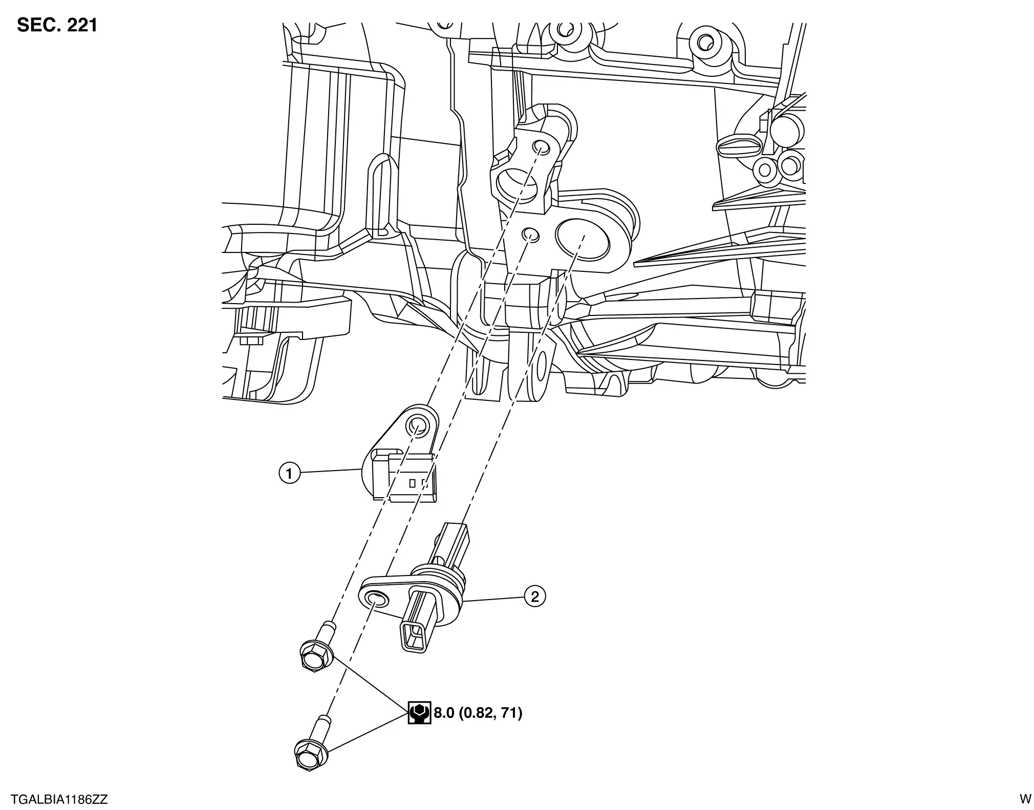
| 1. | Crankshaft position sensor 2 | 2. | Crankshaft position sensor 1 | — | — |
Removal and Installation
REMOVAL
Remove the current sensor from 12V battery. Refer to Removal and Installation.
Remove the engine under cover. Refer to Removal and Installation.
Disconnect harness connector from crankshaft position sensor 1 or crankshaft position sensor 2.
Remove bolt and remove crankshaft position sensor 1 or crankshaft position sensor 2.
CAUTION:
-
Do not drop or shock crankshaft position sensor. If crankshaft position sensor is dropped or shocked, replace with new sensor.
-
Do not allow metal fillings, etc. to get on the sensor's front edge magnetic area.
-
Do not allow tip of crankshaft position sensor to contact magnet.
INSTALLATION
Installation is in the reverse order of removal.
-
Perform "ADDITIONAL SERVICE WHEN REMOVING BATTERY NEGATIVE TERMINAL". Refer to Required Procedure After Battery Disconnection.
-
If crankshaft position sensor 1 or crankshaft position sensor 2 is replaced, perform "ELECTRIC IVT CONTROL ACTUATOR POSITION LEARNING". Refer to Description.
Other materials:
Installation d'un dispositif de retenue pour enfant dos Ă la route Ă l'aide des
ceintures de sécurité
AVERTISSEMENT
Pour votre Nissan Rogue, la ceinture de sécurité à trois points d'ancrage avec enrouleur à blocage automatique (ALR) doit impérativement être utilisée lors de l'installation d'un dispositif de retenue pour enfant. Ne pas utiliser le mode de blocage des enrouleurs (ALR) peut e ...
Oil Level Sensor Signal Circuit
DiagnosisProcedure
CHECK OIL LEVEL SENSOR CIRCUIT
Ignition switch OFF.
Disconnect combination meter harness connector and oil level sensor harness connector.
Check continuity between combination meter harness connector and oil level sensor harness connector.
Combination meter
Oi ...
Pre-Inspection for Diagnosis
Work Procedure
CHECK CAMERA LENS AND WINDSHIELD
Are camera lens and windshield contaminated with foreign materials?
YES (When the camera lens is contaminated with foreign materials.)>>
Replace front camera unit (Refer to Removal and Installation.) and GO TO 2.
YES (When the windshield ...