Nissan Rogue (T33) 2021-Present Service Manual: Engine Mounting Insulator
Engine Mounting Insulator (rh)
Exploded View
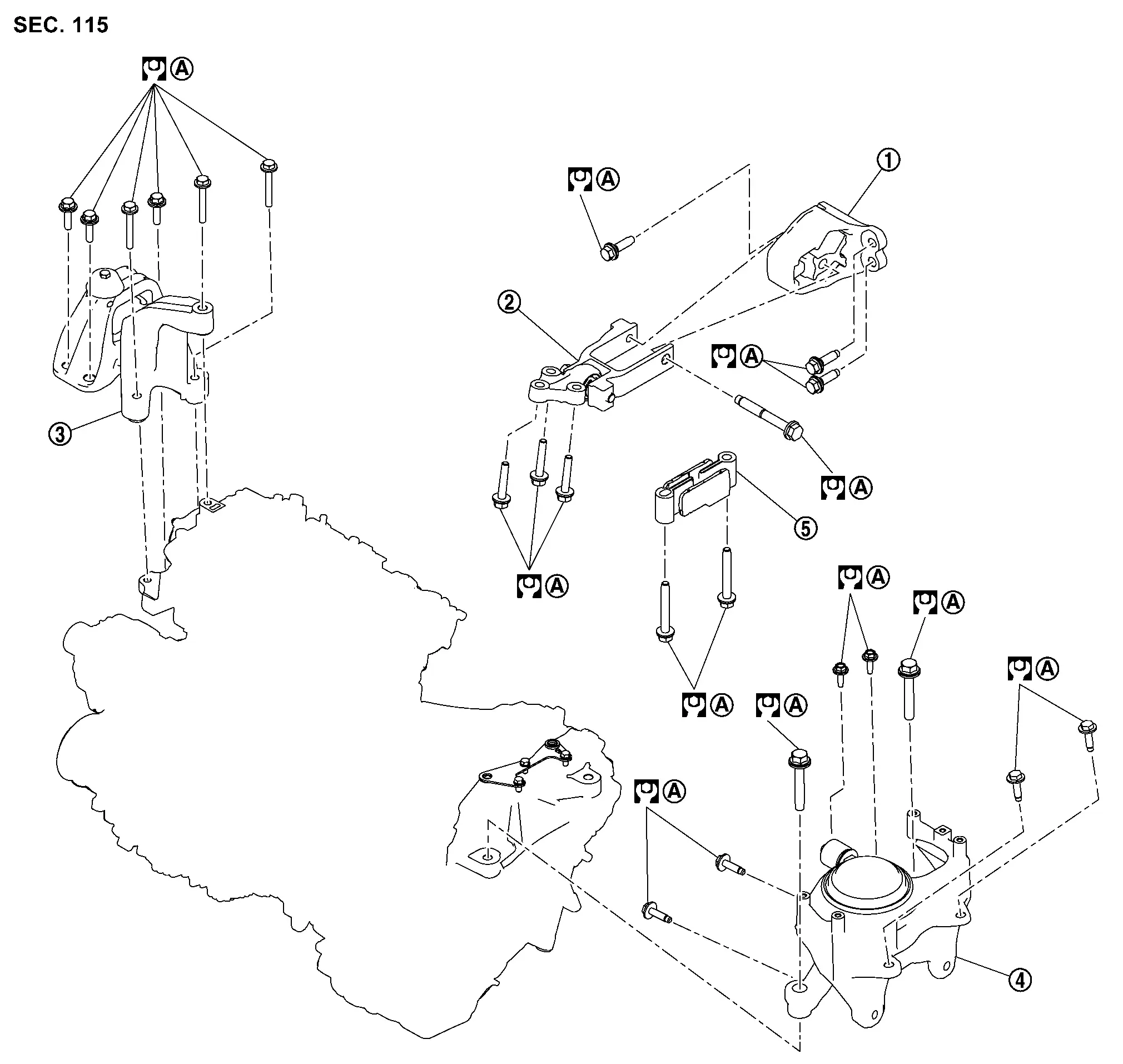
| 1. | Torque rod (RH) | 2. | Torque rod bracket (RH) | 3. | Engine mounting insulator (RH) |
| 4. | Engine mounting insulator (LH) | 5. | Torque rod (LH) | A | Refer to Removal and Installation. |
Removal and Installation
REMOVAL
Remove the engine under cover. Refer to Removal and Installation.
Support the engine and transaxle assembly using a suitable jack.
CAUTION:
Do not damage the oil pan (lower) or transaxle oil pan when supporting the engine and transaxle assembly.
Remove the engine cover. Refer to Removal and Installation.
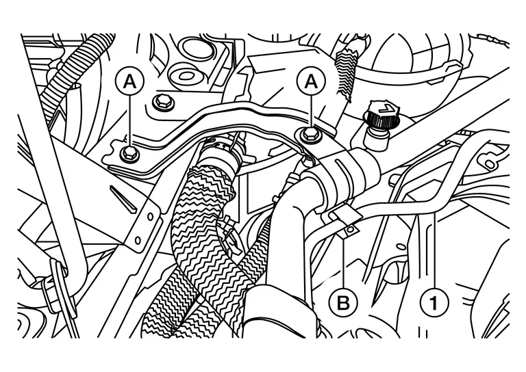
Remove the bolts (A), separate the high-pressure pipe (1) from the retainer (B) and remove the bracket.
Remove the bolts and reposition the reservoir tank. Refer to Exploded View (Radiator).
Remove the bolts and reposition the reservoir tank. Refer to Exploded View (Sub radiator).
Remove the engine mounting insulator (RH) bolts and remove the engine mounting insulator (RH).
INSTALLATION
Install the engine mounting insulator bolts (RH) using the following procedure:Hand tighten the bolts (A) as shown.
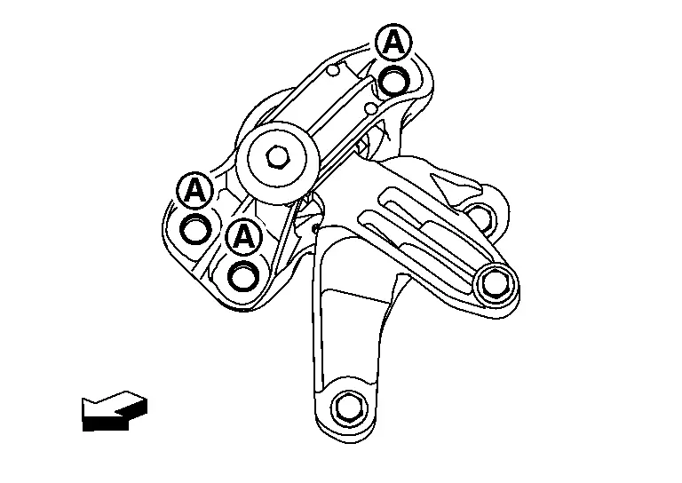
| : Nissan Ariya Vehicle front |
| : Nissan Ariya Vehicle front |
| Bolt | : 62.0 Nôñm (6.3 kg-m, 46 ft-lb) |
| : Nissan Ariya Vehicle front |
| Bolt | : 62.0 Nôñm (6.3 kg-m, 46 ft-lb) |
Installation of the remaining components is in the reverse order of removal.
Engine Mounting Insulator (lh)
Exploded View
| 1. | Torque rod (RH) | 2. | Torque rod bracket (RH) | 3. | Engine mounting insulator (RH) |
| 4. | Engine mounting insulator (LH) | 5. | Torque rod (LH) | A | Refer to Removal and Installation. |
Removal and Installation
REMOVAL
Remove the front grille cover. Refer to Exploded View.
Remove the air duct (inlet). Refer to Exploded View.
Remove the battery. Refer to Removal and Installation.
Remove the engine cover. Refer to Removal and Installation.
Remove the resonator hose from the resonator.
Remove the EVAP hose from the air duct.
Remove the air duct and the resonator. Refer to Exploded View.
Disconnect the harness retainer from the mass air flow sensor and remove the harness retainer from the air cleaner cover.
Remove the bolt and remove the air cleaner assembly. Refer to Exploded View.
Disconnect the harness connectors from the ECM. Refer to ECM : Removal & Installation.
Press the pawl of engine room harness (1) and pull up the engine room harness in the direction of the arrow.
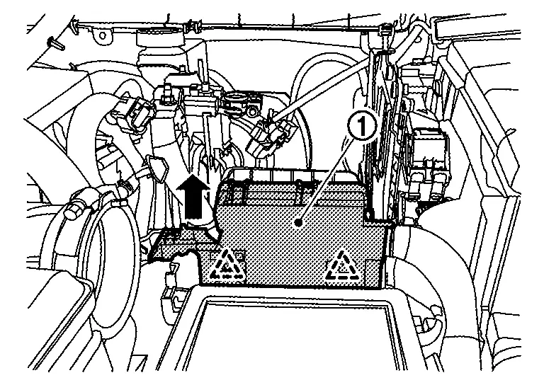
 |
: Pawl |
Remove the battery mounting bracket, battery tray 1 and battery tray 2. Refer to Exploded View.
Remove the engine under cover. Refer to Removal and Installation.
Remove the wheel and tire (LH). Refer to Removal & Installation.
Remove the splash guard (LH). Refer to Exploded View.
Remove the engine mounting insulator (LH) body side lower bolts from underneath the Nissan Ariya vehicle
Support the engine and transaxle assembly using a suitable jack.
CAUTION:
Be careful not to damage the oil pan (lower) or transaxle oil pan when supporting the engine and transaxle assembly.
Remove the engine mounting insulator (LH) bolts and remove the engine mounting insulator (LH).
INSTALLATION
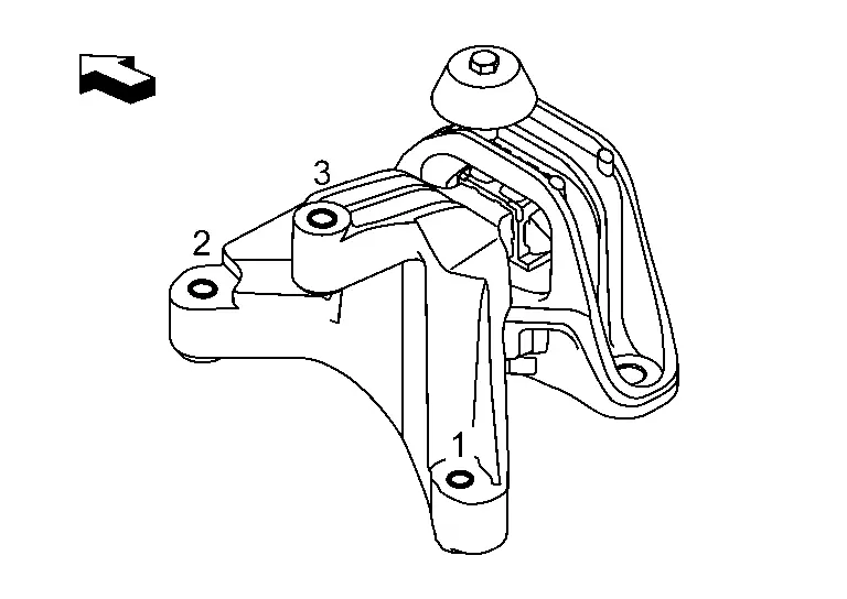
Install the engine mounting insulator bolts (LH) using the following procedure:Tighten the bolts to the specified torque in the sequence shown.
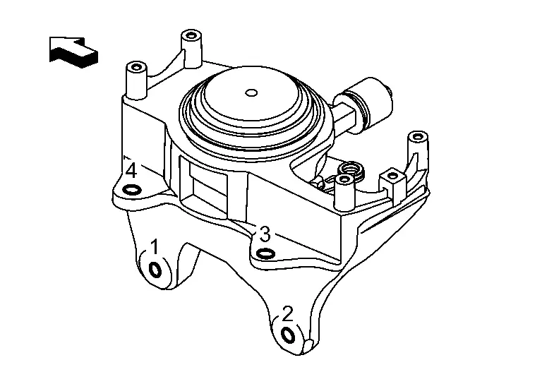
 |
: Nissan Ariya Vehicle front |
| Bolt | 62.0 Nôñm (6.3 kg-m, 46 ft-lb) |
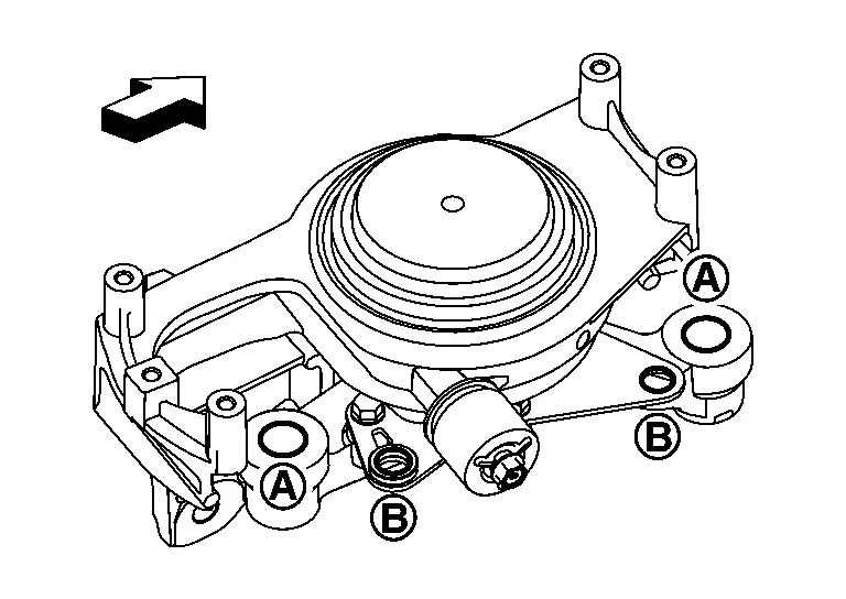
|
: Nissan Ariya Vehicle front |
| Bolt (A) | 110.0 Nôñm (11.0 kg-m, 81 ft-lb) |
| Bolt (B) | : 21.0 Nôñm (2.1 kg-m, 15 ft-lb) |
Installation of the remaining components is in the reverse order of removal.
Other materials:
System Description. System. Power Window System
Power Window System
System Description
SYSTEM DIAGRAM Component Function
Front door switch
Detects front door open/close condition and transmits door switch signal to BCM.
BCM
Controls power window relay.
Controls retained power function.
Power window main switch ...
Entretien gûˋnûˋral
Informations de base
Lors de lãutilisation normale de votre Nissan Rogue, les opûˋrations dãentretien gûˋnûˋral doivent ûˆtre rûˋalisûˋes rûˋguliû´rement et avec rigueur, conformûˋment aux instructions dûˋcrites dans cette section. Toute apparition de bruits anormaux, de vibrations inhabituelle ...
Fuel Pump Control Module
Component Inspection
CHECK FUEL PUMP CONTROL MODULE (FPCM)
Check the voltage between FPCM terminals under the following conditions.
FPCM Condition
Voltage
(Approx.)
Connector + ã
Terminal
B97
6
5
For 1 second after turning ignition switch ON
9.9 V
More than ...