Nissan Rogue (T33) 2021-Present Service Manual: Kr15ddt :: Unit Removal and Installation. Engine Assembly
Engine Assembly
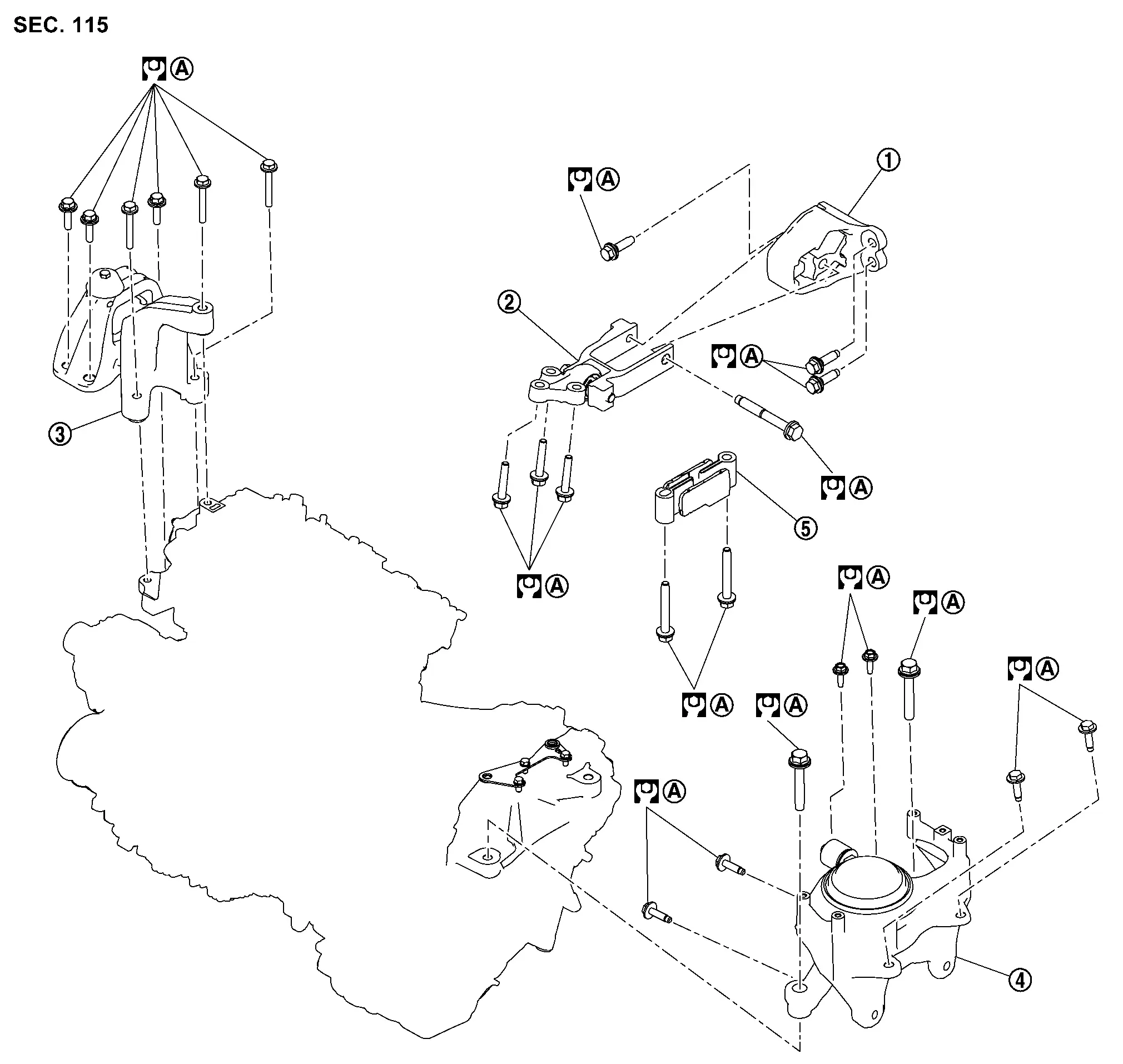
Exploded View
 |
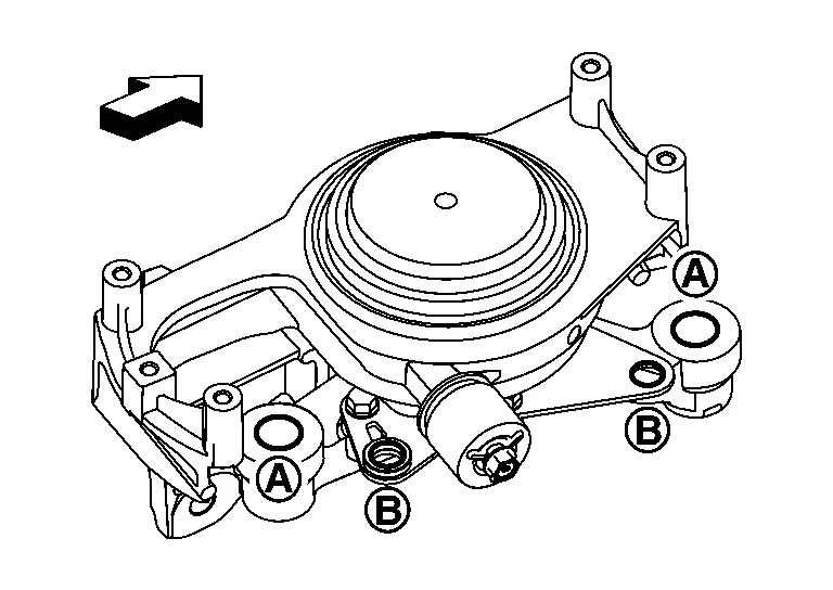
Torque rod RH |  |
Torque rod RH bracket |  |
Engine mounting insulator (RH) |
 |
Engine mounting insulator (LH) |  |
Torque rod LH | ||
 |
Comply with the installation procedure when tightening. Refer to Removal and Installation. | ||||
 |
: Nôñm (kg-m, ft-lb) | ||||
Removal and Installation
REMOVAL
WARNING:
-
Situate the vehicle on a flat and solid surface.
-
Place chocks at front and back of rear wheels.
-
Attach proper slingers and bolts described in EPC if engine slingers are not equipped.
CAUTION:
-
Always be careful to work safely, avoid forceful or uninstructed operations.
-
Never start working until exhaust system and coolant are cool enough.
-
If items or work required are not covered by the engine section, refer to the applicable sections.
-
Always use the support point specified for lifting.
-
Use either 2-pole lift type or separate type lift as best you can. If board-on type is used for unavoidable reasons, support at the rear axle jacking point with a transmission jack or similar tool before starting work, in preparation for the backward shift of center of gravity.
-
For supporting points for lifting and jacking point at rear axle, refer to Garage Jack and Safety Stand and 2-Pole Lift.
 NOTE:
NOTE:
When removing components such as hoses, tubes/lines, etc., cap or plug openings to prevent fluid from spilling.
Outline
Remove the engine and the transaxle assembly from the vehicle downward. Separate the engine and the transaxle.
Preparation
Release fuel pressure. Refer to Work Procedure.
Drain engine coolant from radiator. Refer to Draining.
CAUTION:
Perform this step when the engine is cold.
Drain charge air cooler coolant from sub-radiator. Refer to Draining.
CAUTION:
Perform this step when the engine is cold.
Remove the following parts.
-
Engine cover: Refer to Removal and Installation .
-
Battery and battery tray 2: Refer to Removal and Installation.
-
Air duct, air duct inlet, air cleaner assembly and resonator: Refer to Removal and Installation.
-
Front road wheels and tires: Refer to Removal & Installation.
-
Front fender protector (RH and LH): Refer to Removal and Installation.
-
Splash guard protector (RH and LH): Refer to Removal and Installation.
-
Exhaust front tube: Refer to Removal and Installation.
-
Front bumper: Refer to Removal and Installation..
-
Front bumper reinforcement: Refer to Removal and Installation.
Discharge refrigerant from A/C circuit. Refer to Recycle Refrigerant.
Engine Room LH
Disconnect all connections of engine harness around the engine mounting insulator (LH), and then temporarily secure the engine harness into the engine side.
CAUTION:
Protect connectors using a resin bag against foreign materials during the operation.
Remove battery tray 1. Refer to Removal and Installation.
Disconnect the cooling fan harness connector and clamp.
For models without ProPILOT Assist 2.1, disconnect the brake booster vacuum hose on the engine side. Refer to Removal and Installation.
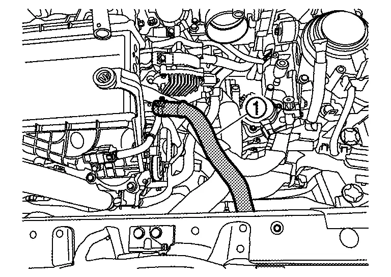
Disconnect the heater hoses (1) on the engine side.
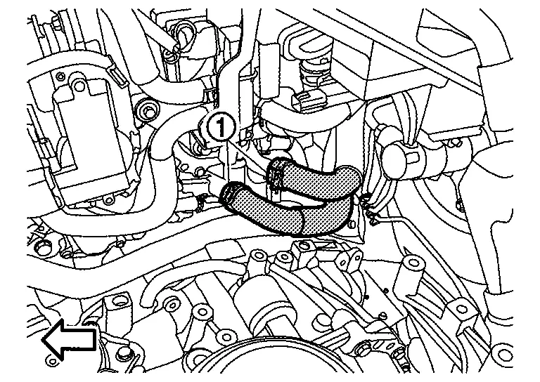
 |
: Nissan Ariya Vehicle front |
Disconnect fuel feed hose quick connector (1) at engine side. Refer to Removal and Installation.
|
: Nissan Ariya Vehicle front |
Remove the quick connector (1) of EVAP canister hose, and remove EVAP canister hose clip (A).
|
: Nissan Ariya Vehicle front |
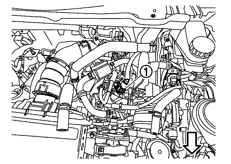
Disconnect the radiator hose (upper) on the engine side.
Remove charge air cooler water hose (1) (charge air cooler side).
Engine Room Underbody LH
Remove the engine harness (A) from the relay box (1).
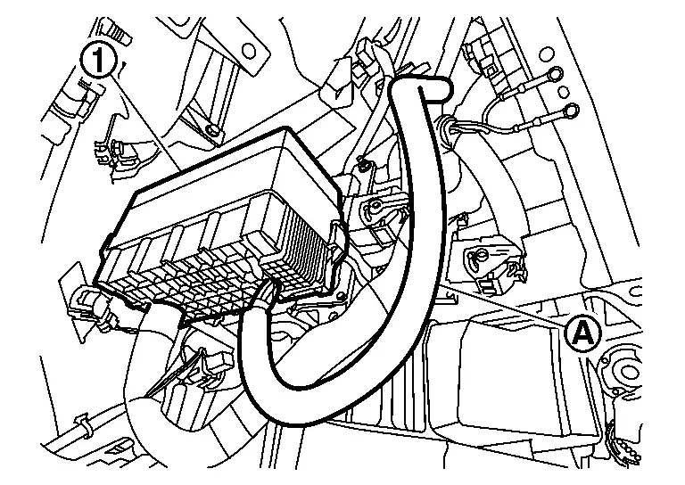
Remove the engine harness connectors (A) from the units.
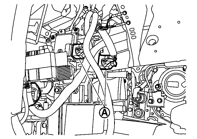
Remove ground cable bolts (A).
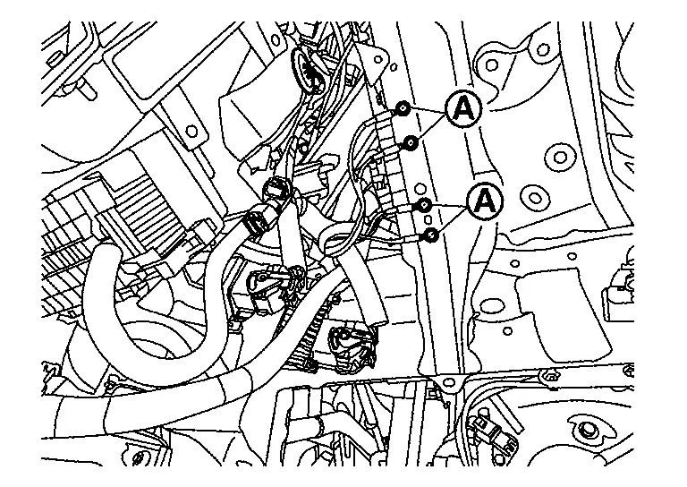
Remove ground cable mounting nut (A) at transaxle side.
|
: Nissan Ariya Vehicle front |
Engine Room RH
For models with ProPILOT Assist 2.1, remove the "B" terminal from the sub starter & generator. Refer to Exploded View.
For models with ProPILOT Assist 2.1, remove "B" terminal harness retainers from engine assembly and reposition harness.
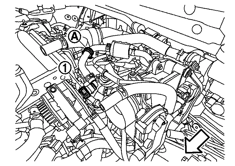
Disconnect high pressure flexible hose and low pressure flexible hose from A/C compressor, and temporarily fasten on Nissan Ariya vehicle with a rope. Refer to Removal and Installation.
Remove ground cable at engine side.
Remove the reservoir tank hose (for engine). Refer to Removal and Installation.
Disconnect reservoir tank hoses on the reservoir tank side (for charge air cooler). Refer to Removal and Installation.
Vehicle inside
Disconnect steering column assembly at steering gear assembly side. Refer to Removal and Installation.
Vehicle Underbody
Disconnect A/C high pressure piping from condenser, and temporarily fasten it on vehicle with a rope. Refer to Exploded View.
Remove propeller shaft (AWD models). Refer to Removal and Installation.
Fasten the radiator at the upper radiator core support with a rope or similar.
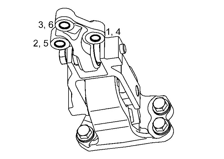
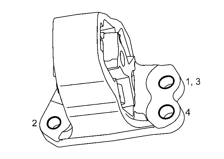
Remove torque rod LH mounting bolts in the reverse order as shown in the figure.
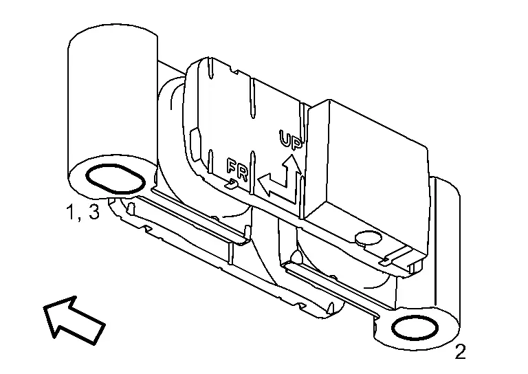
|
: Nissan Ariya Vehicle front |
NOTE:
Disregard the numerical order No. 3 in removal.
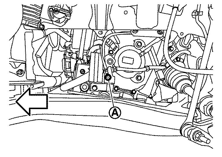
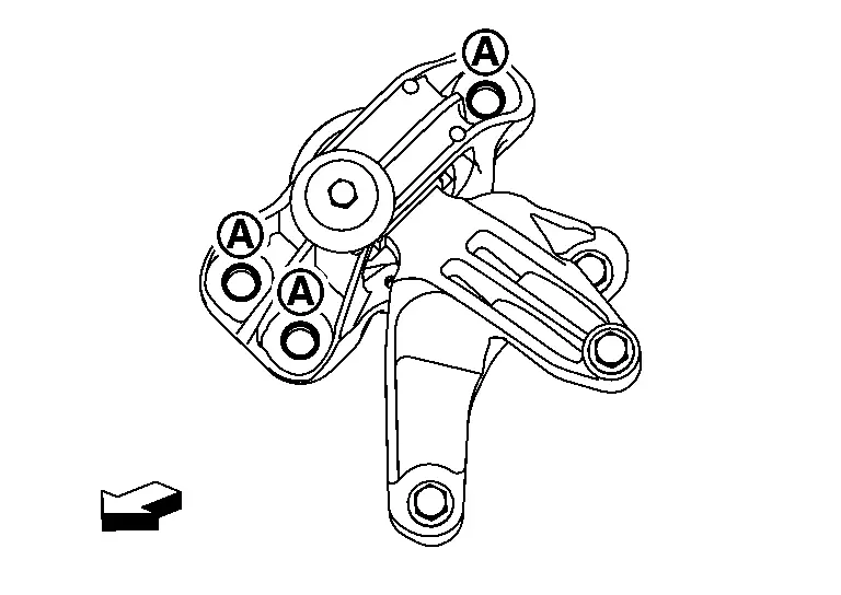
Remove torque rod RH mounting bolt (A).
CAUTION:
Never loosen the bolt (A) because it cannot be disassembled. If accidentally loosen the bolt, tighten the bolt as shown in the figure (specified torque).
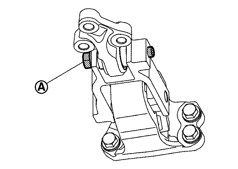
|
: 180.0 Nôñm (18.0 kg-m, 133 ft-lb) | |
Remove torque rod RH mounting bolts in the reverse order as shown in the figure.
NOTE:
Disregard the numerical order No. 4, No. 5 and No. 6 in removal.
Remove torque rod RH mounting bolts in the reverse order as shown in the figure.
NOTE:
Disregard the numerical order No. 3 in removal.
Remove front suspension member. Refer to Removal and Installation.
Disconnect the radiator hose (lower) on the radiator side. Refer to Removal and Installation.
Remove front drive shafts (RH and LH). Refer to the following:
-
2WD models: Refer to Removal and Installation.
-
AWD models: Refer to Removal and Installation.
Removal
Use a manual lift table caddy (commercial service tool) or equivalently rigid tool such as a transmission jack. Securely support bottom of the engine and the transaxle assembly.
CAUTION:
Put a piece of wood or an equivalent as the supporting surface, secure a completely stable condition.
Remove the engine mounting insulator bolts (RH) as follows:Remove the engine mounting insulator bolts (RH) in the reverse order as shown in the figure.
|
: Nissan Ariya Vehicle front |
Remove the engine mounting insulator bolts (LH) as follows:Loosen the mounting bolts (A) and (B) as shown in the figure.
|
: Nissan Ariya Vehicle front |
Remove engine and transaxle assembly from the vehicle by lowering (or raising the lift) a bottom supporting tool, such as manual lift table caddy (commercial service tool) or mission jack.
CAUTION:
-
Check that no part interferes with the Nissan Ariya vehicle side.
-
Before and during this lifting, always check if any harnesses are left connected.
-
During the removal, always be careful to prevent the Nissan Ariya vehicle from falling off the lift due to changes in the center of gravity.
-
If necessary, support the Nissan Ariya vehicle by setting jack or suitable tool at the rear.
Remove engine mounting insulator (RH) bolts, if necessary.
-
Loosen the mounting bolts (A) as shown in the figure.
|
: Nissan Ariya Vehicle front |
Remove the engine mounting insulator bolts (LH) as follows, if necessary:Remove the engine mounting insulator bolts (LH) in the reverse order as shown in the figure.
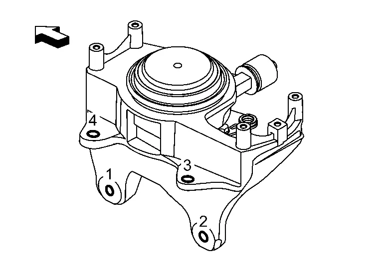
|
: Nissan Ariya Vehicle front |
Separation
Install engine slingers into front left of engine mount bracket (RH) and rear right of cylinder head.
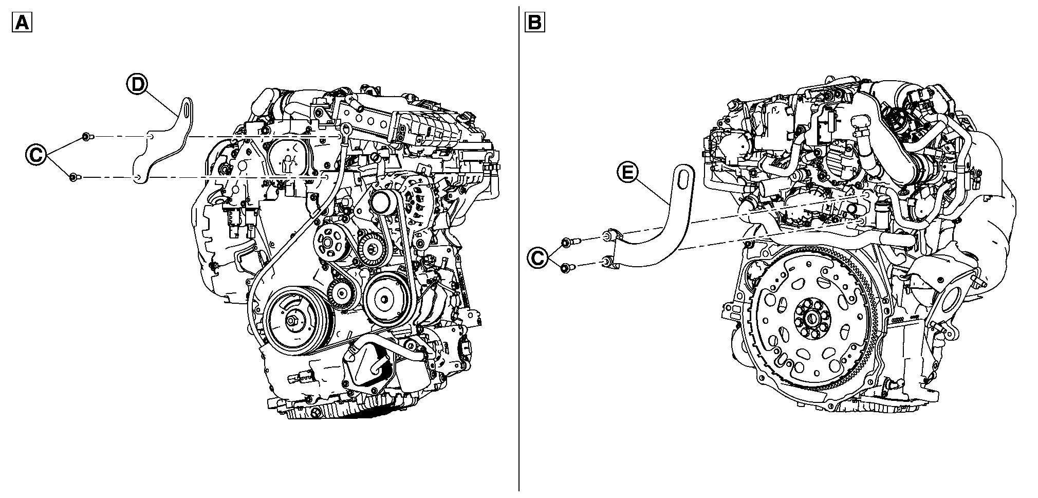
| Slinger bolts (C) | ||
| Engine slinger (D) front cover sideã: | |
: 32.9 Nôñm (3.4 kg-m, 24 ft-lb) |
| Engine slinger (E) cylinder head sideã: | |
: 45.0 Nôñm (4.6 kg-m, 33 ft-lb) |
| (A) | : Engine front side | |
| (B) | : Engine rear side | |
Remove starter motor. Refer to Removal and Installation.
Lift with a hoist and separate the engine from the transaxle assembly. Refer to Removal and Installation.
INSTALLATION
Note the following, and install in the reverse order of removal.
CAUTION:
-
Never allow engine oil to get on engine mounting insulator. Be careful not to damage engine mounting insulator.
-
Check that each mounting insulator is seated properly, and tighten mounting nuts and bolts.
-
If engine assembly replaced, perform "IDLE AIR VOLUME LEARNING". Refer to Description, "AIR FUEL RATIO INITIAL LEARNING" Refer to Description and "ELECTRIC IVT CONTROL ACTUATOR POSITION LEARNING". Refer to Description.
Preparation
Install the torque rod RH bolts as follows:Tighten the bolt in order number of as shown in the figure (specified torque).
| 1 | : Temporarily | ||
| 2 ã 4: | |
: 105.0 Nôñm (11.0 kg-m, 77 ft-lb) | |
Install the engine mounting insulator bolts (LH) as follows:Tighten the bolt in order number of as shown in the figure (specified torque).
|
: Nissan Ariya Vehicle front |
|
: 62.0 Nôñm (6.3 kg-m, 46 ft-lb) | |
Install the engine mounting insulator bolts (RH) as follows:Temporarily tighten the bolts (A) as shown in the figure.
|
: Nissan Ariya Vehicle front |
Installation
Lift up the engine assembly to the vehicle.
Install the engine mounting insulator bolts (RH) as follows:Tighten the bolt in order number of as shown in the figure (specified torque).
|
: Nissan Ariya Vehicle front |
|
: 62.0 Nôñm (6.3 kg-m, 46 ft-lb) | |
Install the engine mounting insulator bolts (LH) as follows:Tighten the bolts (A) and (B) in order number of as shown in the figure (specified torque).
|
: Nissan Ariya Vehicle front |
| (A): | |
: 110.0 Nôñm (11.0 kg-m, 81 ft-lb) | |
| (B): | |
: 21.0 Nôñm (2.1 kg-m, 15 ft-lb) | |
Install the engine mounting insulator bolts (RH) as follows:Tighten the bolt (A) as shown in the figure (specified torque).
|
: Nissan Ariya Vehicle front |
|
: 62.0 Nôñm (6.3 kg-m, 46 ft-lb) | |
Remove bottom supporting tool, such as manual lift table caddy (commercial service tool) or mission jack.
NOTE:
Check the engine mounting insulator is not twisted.
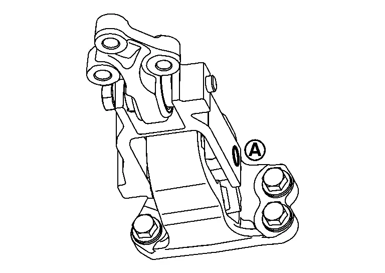
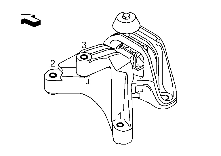
Install the torque rod RH bracket mounting bolts as follows:
-
Tighten the bolts in order number of as shown in the figure.
1 ã 3: Temporarily 4 ã 6: : 105.0 Nôñm (11.0 kg-m, 77 ft-lb)
-
Tighten the bolt (A) as shown in the figure (specified torque).
: 180.0 Nôñm (18.0 kg-m, 133 ft-lb)
NOTE:
Check the torque rod RH is not twisted.
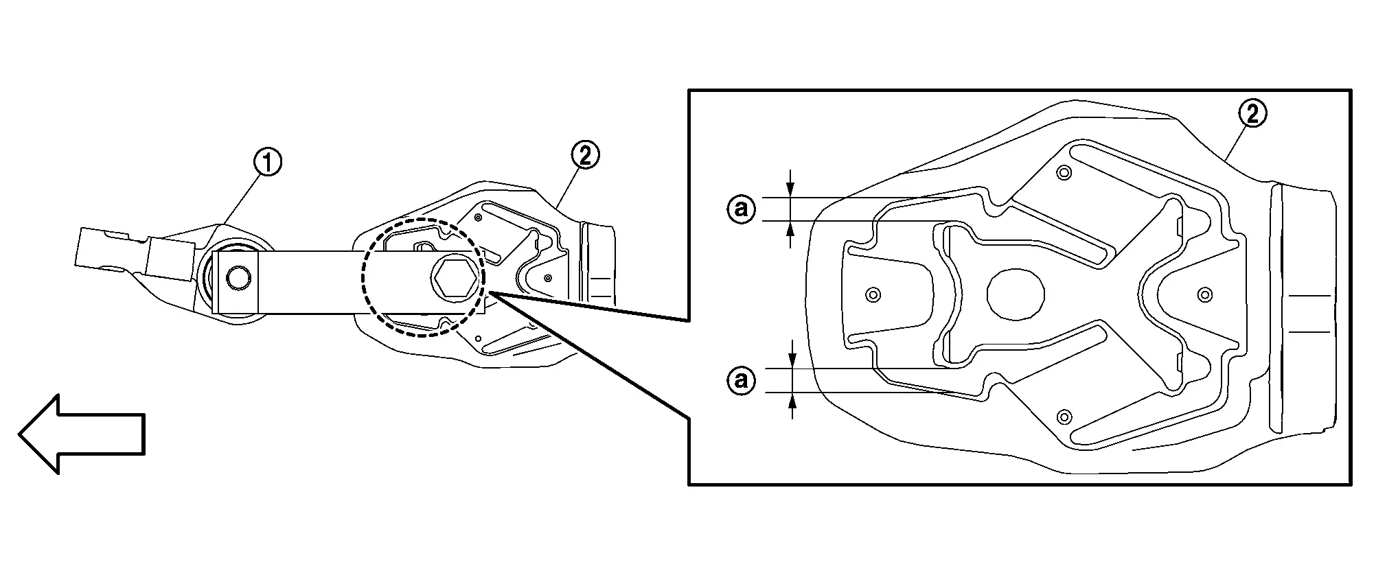
| (1) | : Torque rod RH bracket |
| (2) | : Torque rod RH |
| (a) |
: 5 mm (0.197 in) |
|
: Nissan Ariya Vehicle front |
Install the torque rod LH mounting bolts as follows:
-
For NMK production, run the bolt at position one down at speed using a commercially available battery impact driver.
-
Tighten the bolts in the sequence shown.
1: Temporarily 2 ã 3: : 105.0 Nôñm (11.0 kg-m, 77 ft-lb) : Nissan Ariya Vehicle front NOTE:
-
Check the engine torque rod LH is not twisted.
-
After installation make sure that the flags (C) are aligned or damage to torque rod LH will result.
-
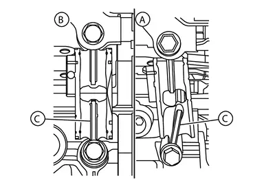
| (A) | :NG |
| (B) | :OK |
Inspection
INSPECTION AFTER INSTALLATION
Inspection for Leakage
The following are procedures for checking fluids leakage, lubricates leakage, and exhaust gases leakage.
-
Before starting engine, check oil/fluid levels including engine coolant and engine oil. If less than required quantity, fill to the specified level. Refer to Fluids and Lubricants.
-
Use procedure below to check for fuel leakage.
-
Turn ignition switch ãONã (with engine stopped). With fuel pressure applied to fuel piping, check for fuel leakage at connection points.
-
Start engine. With engine speed increased, check again for fuel leakage at connection points.
-
-
Run engine to check for unusual noise and vibration.
-
Warm up engine thoroughly to check there is no leakage of fuel, exhaust gases, or any oil/fluids including engine oil and engine coolant.
-
Bleed air from lines and hoses of applicable lines, such as in cooling system.
-
After cooling down engine, again check oil/fluid levels including engine oil and engine coolant. Refill to the specified level, if necessary.
Summary of the inspection items: Items Before starting engine Engine running After engine stopped Engine coolant Level Leakage Level Engine oil Level Leakage Level Transmission / transaxle fluid AT & CVT Models Leakage Level / Leakage Leakage MT Models Level / Leakage Leakage Level / Leakage Other oils and fluids* Level Leakage Level Fuel Leakage Leakage Leakage Exhaust gases ã Leakage ã *: Power steering fluid, brake fluid, etc.
Other materials:
Freins
Informations de base
Si le systû´me de freinage du Nissan Rogue ne fonctionne pas correctement, faites-le contrûÇler sans dûˋlai par un concessionnaire NISSAN.
Freins û rattrapage automatique d'usure
Le Nissan Rogue est ûˋquipûˋ de freins û rattrapage automatique dãusure. Les freins û disq ...
Commande de feux de dûˋtresse
Appuyez sur cette commande pour signaler aux autres usagers que vous devez vous arrûˆter ou stationner en urgence. Tous les clignotants du Nissan Rogue fonctionnent alors simultanûˋment.
AVERTISSEMENT
En cas dãarrûˆt dãurgence, garez le vûˋhicule le plus loin possible de la circulatio ...
P0420 Three Way Catalyst Function
DTC Description
The ECM monitors the switching frequency ratio of air fuel ratio (A/F) sensor 1 and heated oxygen sensor 2.A
three way catalyst (manifold) with high oxygen storage capacity will
indicate a low switching frequency of heated oxygen sensor 2. As oxygen
storage capacity decreases, ...