Nissan Rogue (T33) 2021-Present Service Manual: Front Oil Seal
Removal and Installation
REMOVAL
Remove the drive belt. Refer to Removal and Installation.
Remove the fender protector. Refer to Removal and Installation.
Remove crankshaft pulley using the following procedure:Loosen crankshaft pulley bolt.
CAUTION:
Do not remove the crankshaft pulley bolt as it is used as a supporting point for a suitable puller.
 NOTE:
NOTE:
There should be approximately a 5 mm (0,20 in) gap between the flange on crankshaft pulley bolt and crankshaft pulley damper.
Attach a suitable puller (A) to the threaded holes on the crankshaft pulley damper (1) and remove crankshaft pulley damper.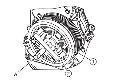
CAUTION:
-
Do not use a claw or hook style puller because damage to crankshaft pulley damper may occur.
-
Do not allow the bolts for the suitable puller to thread through crankshaft pulley damper and contact crankshaft pulley because damage to crankshaft pulley may occur.
| (2) | : Crankshaft pulley bolt |
CAUTION:
Do not use a claw or hook style puller because damage to crankshaft pulley damper may occur.
| Thread | Length | |
| Bolt | M16x1.5 | 100 mm (1.38 in) |
Remove front oil seal with a suitable tool.
CAUTION:
-
Do not damage front cover and crankshaft.
-
Do not reuse front oil seal.
INSTALLATION
Apply new engine oil to new front oil seal joint surface and seal lip.
Install front oil seal so that each seal lip is oriented as shown.
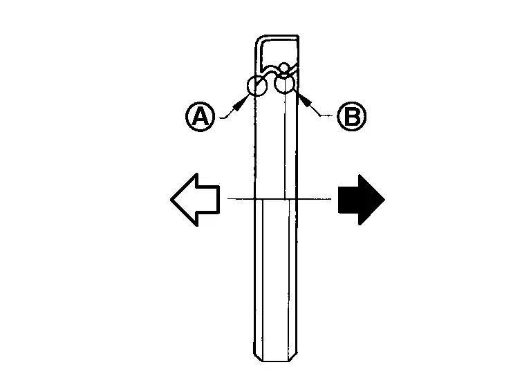
| A | : Dust seal lip |
| B | : Oil seal lip |
 |
: Engine outside |
 |
: Engine inside |
-
Press-fit front oil seal using a suitable drift with outer diameter 58 mm (2.28 in) and inner diameter 46 mm (1.81 in).
CAUTION:
-
Do not damage front cover or crankshaft.
-
Press-fit front oil seal straight to avoid causing burrs or tilting.
NOTE:
Front oil seal (1) should be installed within the range shown from the front face (A).
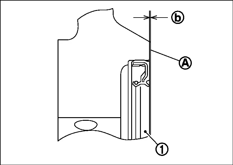
Dimension b : 0 ŌĆō 0.8 mm (0.0 ŌĆō 0.031 in) : Engine front -
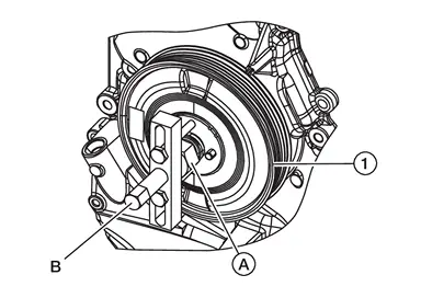
Install crankshaft pulley using the following procedure:Align holes in crankshaft pulley damper (1) with pins in crankshaft pulley (2) and press until click sound is heard from circlip (B).
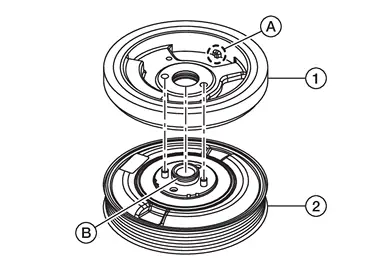
| (A) | : Crankshaft key position indicator |
CAUTION:
Do not damage front oil seal lip portion.
Secure crankshaft pulley with a pulley holder. Apply new engine oil to thread and seat surfaces of crankshaft pulley bolt. Tighten crankshaft pulley bolt to the specified torque.| Crankshaft pulley bolt | : 29.4 N┬Ęm (3.0 kg-m, 22 ft-lb) |
CAUTION:
Check and confirm the tightening angle using angle wrench [SST: KV10112100 (BT8653-A)]. Avoid judgment by visual inspection without Tool.
| Tightening angle | : 100┬░ - 106┬░ |
Installation of the remaining components is in the reverse order of removal.
Other materials:
P026b Injection Timing
DTC Description
DTC DETECTION LOGIC DTC
CONSULT screen terms
(Trouble diagnosis content)
DTC detection condition
P026B
00
Injection timing
Diagnosis condition
ŌĆö
Signal
ŌĆö
Threshold
ECM does not control fuel injection timing properly when engine is running ...
Dtc/circuit Diagnosis. U2a06-88 Comm Bus Off V-Fd
DTC Description
DESCRIPTIONCAN (Controller Area Network) is a serial
communication line for real time applications. It is an on-Nissan Ariya
vehicle multiplex communication line with high data communication speed
and excellent error detection ability. Modern Nissan Ariya vehicle is
equipped ...
Modes de fonctionnement des essuie-glaces
Type A (selon ├®quipement)
Type B (selon ├®quipement)
Les commandes de visibilit├® de votre Nissan Rogue s'activent lorsque le contact est sur "ON" :
Mode AUTO / Intermittent :
- Type A (Automatique) : Le Nissan Rogue ajuste seul la vitesse selon l'intensit├® de la pluie ...