Nissan Rogue (T33) 2021-Present Service Manual: System
Cvt Control System
System Description
SYSTEM DIAGRAM
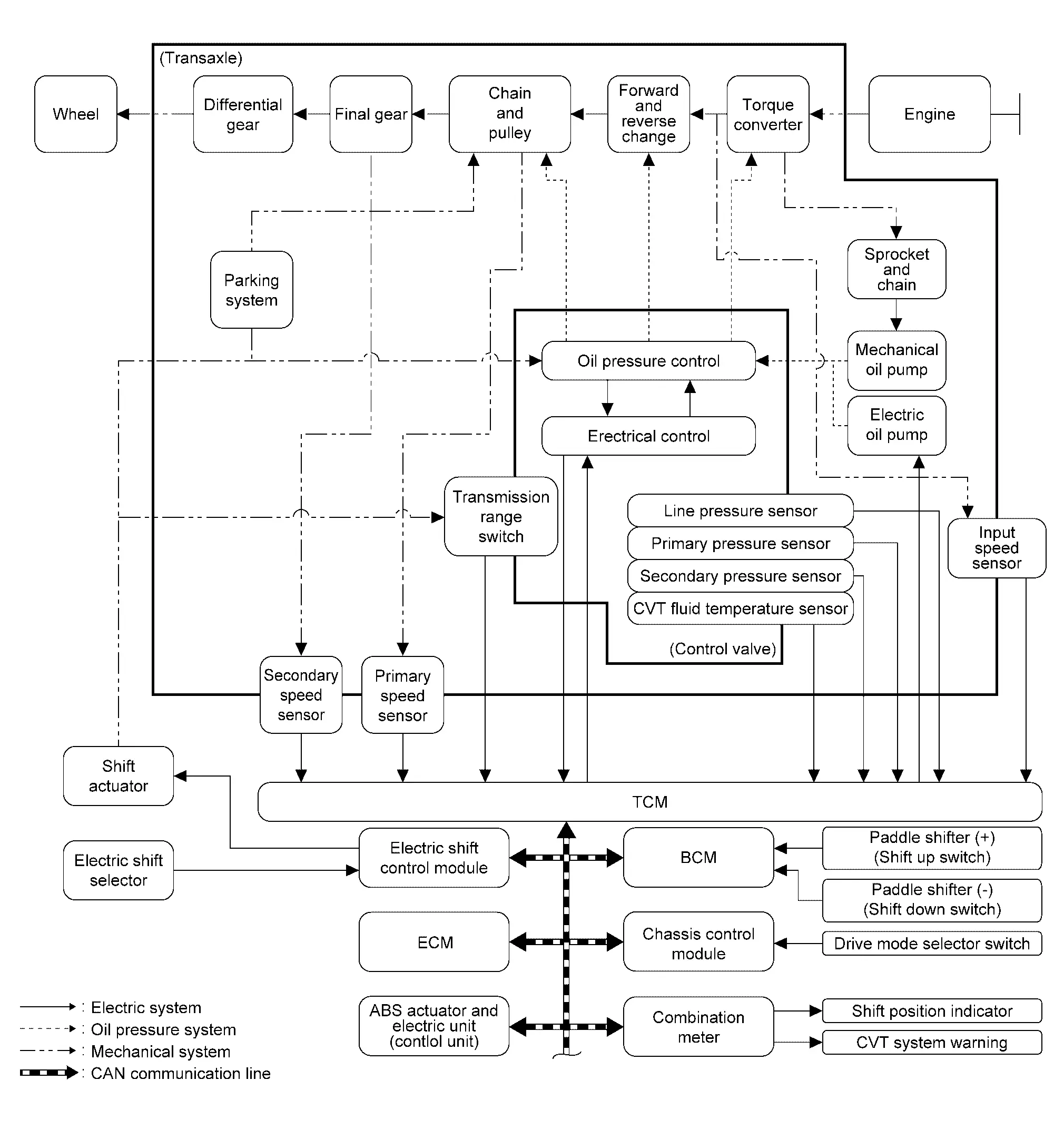
| Component | Function | |
|---|---|---|
| ECM |
Mainly transmits the following signal to TCM via CAN communication.
Mainly receives the following signals from TCM via CAN communication.
|
|
| TCM | TCM | |
| BCM |
Mainly transmits the following signal to TCM via CAN communication
|
|
| ABS actuator and electronic unit (control unit) |
Mainly transmits the following signal to TCM via CAN communication
|
|
| Combination meter |
Mainly receives the following signals from TCM via CAN communication.
|
|
| Malfunction indicator lamp (MIL) | Malfunction Indicator Lamp (MIL) (FULL TFT METER) or Malfunction Indicator Lamp (MIL) (7 INCH INFORMATION DISPLAY) | |
| Shift position indicator | Shift position indicator | |
| Drive mode select switch | Drive Mode Select Switch | |
| Input speed sensor | Input Speed Sensor | |
| Secondary speed sensor | Secondary Speed Sensor | |
| Primary speed sensor | Primary Speed Sensor | |
| Electric oil pump | Electric Oil Pump | |
| Control valve | Transmission range switch | Transmission Range Switch |
| CVT fluid temperature sensor* | CVT Fluid Temperature Sensor | |
| Primary pressure sensor* | Primary Pressure Sensor | |
| Secondary pressure sensor* | Secondary Pressure Sensor | |
| Line pressure solenoid valve* | Line Pressure Solenoid Valve | |
| Primary pressure solenoid valve* | Primary Pressure Solenoid Valve | |
| Secondary pressure solenoid valve* | Secondary Pressure Solenoid Valve | |
| Torque converter clutch solenoid valve* | Torque Converter Clutch Solenoid Valve | |
| Select solenoid valve* | Select Solenoid Valve | |
| Paddle shifter | Paddle Shifter | |
| Shift actuator | Shift Actuator | |
| Electric shift selector | Electric Shift Selector | |
| Electric shift control module |
Mainly transmits the following signal to TCM via CAN communication
|
|
MAIN CONTROL CONTENTS OF TCM
| Controls | Reference |
| Line pressure control | System Description |
| Shift control | System Description |
| Select control | System Description |
| Lock-up control | System Description |
| Drive Mode Selector | System Description |
| Stop/start system | System Description |
| Fail-safe | Fail-safe |
| Self-diagnosis function | CONSULT Function |
| Communication function with CONSULT | CONSULT Function |
For electric shift system, refer to System Description.
LIST OF CONTROL ITEMS AND INPUT/OUTPUT
| Control Item | Shift control | Line pressure control | Select control | Lock-up control | Fail-safe function* | |
|---|---|---|---|---|---|---|
| Input |
Engine torque signal (CAN communication) |
├Ś | ├Ś | ├Ś | ├Ś | ├Ś |
|
Engine speed signal (CAN communication) |
├Ś | ├Ś | ├Ś | ├Ś | ├Ś | |
|
Accelerator pedal position signal (CAN communication) |
├Ś | ├Ś | ├Ś | ├Ś | ||
|
Closed throttle position signal (CAN communication) |
├Ś | ├Ś | ├Ś | |||
|
Stop lamp switch signal (CAN communication) |
├Ś | ├Ś | ├Ś | ├Ś | ||
| Primary pressure sensor | ├Ś | |||||
| Secondary pressure sensor | ├Ś | ├Ś | ├Ś | |||
| CVT fluid temperature sensor | ├Ś | ├Ś | ├Ś | ├Ś | ├Ś | |
| Primary speed sensor | ├Ś | ├Ś | ├Ś | ├Ś | ├Ś | |
| Secondary speed sensor | ├Ś | ├Ś | ├Ś | ├Ś | ||
| Input speed sensor | ├Ś | ├Ś | ├Ś | ├Ś | ├Ś | |
| Transmission range switch | ├Ś | ├Ś | ├Ś | ├Ś | ├Ś | |
|
Electric shift selector signal (CAN communication) |
├Ś | ├Ś | ├Ś | |||
|
Paddle shifter shift up/down signal (CAN communication) |
├Ś | |||||
| Output | Line pressure solenoid valve | ├Ś | ├Ś | ├Ś | ├Ś | |
| Primary pressure solenoid valve | ├Ś | ├Ś | ├Ś | |||
| Torque converter clutch solenoid valve | ├Ś | ├Ś | ||||
| Secondary pressure solenoid valve | ├Ś | ├Ś | ├Ś | |||
| Select solenoid valve | ├Ś | ├Ś | ├Ś | |||
| Electric oil pump | ├Ś | ├Ś | ||||
|
Shift position indicator (CAN communication) |
├Ś | |||||
*: If these input/output signals show errors, TCM activates the fail-safe function.
Fail-safe
TCM has a fail-safe mode. The mode functions so that operation can be continued even if the signal circuit of the main electronically controlled input/output parts is damaged.
If the vehicle shows following behaviors including ŌĆ£poor accelerationŌĆØ, a malfunction of the applicable system is detected by TCM and the Nissan Ariya vehicle may be in a fail-safe mode. At this time, check the DTC and perform inspection and repair according to the malfunction diagnosis procedures.
Fail-safe function
| DTC | Nissan Ariya Vehicle behavior | Conditions of vehicle | |
|---|---|---|---|
| P0604 | 00 |
|
ŌĆö |
| P0605 | 00 |
|
ŌĆö |
| P0606 | 00 |
|
ŌĆö |
| P060A | 00 |
|
ŌĆö |
| P062F | 00 |
|
ŌĆö |
| P06B1 | 00 | Refer to Fail-safe. | ŌĆö |
| P0705 | 00 |
|
ŌĆö |
| P0706 | 00 |
|
ŌĆö |
| P0711 | 00 |
|
Engine coolant temperature when engine start: Temp. Ōēź 10┬░C (50┬░F) |
|
Engine coolant temperature when engine start: ŌłÆ35┬░C (ŌłÆ31┬░F) Ōēż Temp. < 10┬░C (50┬░F) |
||
|
Engine coolant temperature when engine start: Temp. <ŌłÆ35┬░C (ŌłÆ31┬░F) |
||
|
ŌĆö | ||
| P0712 | 00 |
|
Engine coolant temperature when engine start: Temp. Ōēź 10┬░C (50┬░F) |
|
Engine coolant temperature when engine start: ŌłÆ35┬░C (ŌłÆ31┬░F) Ōēż Temp. < 10┬░C (50┬░F) |
||
|
Engine coolant temperature when engine start: Temp. <ŌłÆ35┬░C (ŌłÆ31┬░F) |
||
|
ŌĆö | ||
| P0713 | 00 |
|
Engine coolant temperature when engine start: Temp. Ōēź 10┬░C (50┬░F) |
|
Engine coolant temperature when engine start: ŌłÆ35┬░C (ŌłÆ31┬░F) Ōēż Temp. < 10┬░C (50┬░F) |
||
|
Engine coolant temperature when engine start: Temp. <ŌłÆ35┬░C (ŌłÆ31┬░F) |
||
|
ŌĆö | ||
| P0715 | 00 |
|
ŌĆö |
| P0716 | 00 |
|
ŌĆö |
| P0717 | 00 |
|
ŌĆö |
| P0718 | 00 |
|
ŌĆö |
| P072A | 00 | Refer to Fail-safe. | ŌĆö |
| P0740 | 00 |
|
ŌĆö |
| P0741 | 00 |
|
ŌĆö |
| P0742 | 00 |
|
ŌĆö |
| P0746 | 00 |
|
ŌĆö |
| P0747 | 00 |
|
ŌĆö |
| P0776 | 00 |
|
Nissan Ariya Vehicle speed < 40 km/h (25 MPH) or Input speed < 1300 rpm |
|
Other then the above | ||
| P0777 | 00 |
|
Nissan Ariya Vehicle speed < 40 km/h (25 MPH) or Input speed < 1300 rpm |
|
Other then the above | ||
| P0780 | 00 |
|
ŌĆö |
| P0791 | 00 |
|
ŌĆö |
| P0792 | 00 |
|
ŌĆö |
| P0793 | 00 |
|
ŌĆö |
| P0794 | 00 |
|
ŌĆö |
| P0796 | 00 |
|
Vehicle speed < 40 km/h (25 MPH) or Input speed < 1300 rpm |
|
Other then the above | ||
| P0797 | 00 |
|
Nissan Ariya Vehicle speed < 40 km/h (25 MPH) or Input speed < 1300 rpm |
|
Other then the above | ||
| P07BF | 00 |
|
ŌĆö |
| P07C0 | 00 |
|
ŌĆö |
| P07C1 | 00 |
|
ŌĆö |
| P07C2 | 00 |
|
ŌĆö |
| P07C5 | 00 |
|
ŌĆö |
| P07C6 | 00 |
|
ŌĆö |
| P07E9 | 00 | Refer to Fail-safe. | ŌĆö |
| P07EA | 00 | Refer to Fail-safe. | ŌĆö |
| P07EB | 00 | Refer to Fail-safe. | ŌĆö |
| P07ED | 00 | Refer to Fail-safe. | ŌĆö |
| P07EF | 00 | Refer to Fail-safe. | ŌĆö |
| P07F2 | 00 | Refer to Fail-safe. | ŌĆö |
| P0840 | 00 |
|
ŌĆö |
| P0846 | 00 |
|
ŌĆö |
| P0847 | 00 |
|
ŌĆö |
| P0848 | 00 |
|
ŌĆö |
| P084A | 00 |
|
ŌĆö |
| P084B | 00 |
|
ŌĆö |
| P084C | 00 |
|
ŌĆö |
| P084D | 00 |
|
ŌĆö |
| P0863 | 00 |
|
ŌĆö |
| P0870 | 00 |
|
ŌĆö |
| P0871 | 00 |
|
ŌĆö |
| P0872 | 00 |
|
ŌĆö |
| P0873 | 00 |
|
ŌĆö |
| P0890 | 00 |
|
ŌĆö |
| P0914 | 00 | It becomes the same fail-safe as the DTC (P0604, P0605, P0606, P0607, P060C, P062F, P06B1, P0780 and/or P07EE) detected by the electric shift control module. Refer to Fail-safe. | ŌĆö |
| P0915 | 00 | Refer to Fail-safe . | ŌĆö |
| P0919 | 00 | Refer to Fail-safe . | ŌĆö |
| P0960 | 00 |
|
ŌĆö |
| P0961 | 00 |
|
When a malfunction occurs on the low oil pressure side |
|
When a malfunction occurs on the high oil pressure side | ||
| P0962 | 00 |
|
ŌĆö |
| P0963 | 00 |
|
ŌĆö |
| P0964 | 00 |
|
Nissan Ariya Vehicle speed < 40 km/h (25 MPH) or Input speed < 1300 rpm |
|
Other then the above | ||
| P0966 | 00 |
|
Nissan Ariya Vehicle speed < 40 km/h (25 MPH) or Input speed < 1300 rpm |
|
Other then the above | ||
| P0967 | 00 |
|
Nissan Ariya Vehicle speed < 40 km/h (25 MPH) or Input speed < 1300 rpm |
|
Other then the above | ||
| P0968 | 00 |
|
ŌĆö |
| P0970 | 00 |
|
Nissan Ariya Vehicle speed < 40 km/h (25 MPH) or Input speed < 1300 rpm |
|
Other then the above | ||
| P0971 | 00 |
|
Nissan Ariya Vehicle speed < 40 km/h (25 MPH) or Input speed < 1300 rpm |
|
Other then the above | ||
| P1588 | 00 |
|
ŌĆö |
| P159C | 00 |
|
ŌĆö |
| P159D | 00 |
|
ŌĆö |
| P17F0 | 07 |
|
ŌĆö |
| P17F1 | 07 |
|
ŌĆö |
| P17F2 | 07 |
|
ŌĆö |
| P187E | 09 |
|
ŌĆö |
| P188E | 00 |
|
ŌĆö |
| P18A5 | 00 |
|
ŌĆö |
| P18AB | 00 |
|
ŌĆö |
| P271E | 00 |
|
ŌĆö |
| P272A | 00 | Refer to Fail-safe. | ŌĆö |
| P272B | 00 | Refer to Fail-safe. | ŌĆö |
| P2765 | 00 |
|
ŌĆö |
| P2766 | 00 |
|
ŌĆö |
| P2767 | 00 |
|
ŌĆö |
| P2768 | 00 |
|
ŌĆö |
| P2769 | 00 |
|
ŌĆö |
| P2770 | 00 |
|
ŌĆö |
| P27A1 | 00 |
|
ŌĆö |
| P27A3 | 00 |
|
ŌĆö |
| P27A4 | 00 |
|
ŌĆö |
| P27A5 | 00 |
|
ŌĆö |
| P27A6 | 00 |
|
ŌĆö |
| P27B3 | 00 |
|
ŌĆö |
| P27B5 | 00 |
|
ŌĆö |
| P27EB | 00 |
|
ŌĆö |
| P27EC | 00 |
|
ŌĆö |
| P27EF | 00 |
|
ŌĆö |
| P27F0 | 00 |
|
ŌĆö |
| P2808 | 00 |
|
ŌĆö |
| P2809 | 00 |
|
ŌĆö |
| P2812 | 00 |
|
ŌĆö |
| P2814 | 00 |
|
ŌĆö |
| P2815 | 00 |
|
ŌĆö |
| P28ED | 00 |
|
ŌĆö |
| P28EE | 00 |
|
ŌĆö |
| U0073 | 00 |
|
ŌĆö |
| U007A | 00 |
|
ŌĆö |
| U0100 | 00 |
|
ŌĆö |
| U0101 | 00 | Refer to Fail-safe. | ŌĆö |
| U0103 | 00 |
|
ŌĆö |
| U0115 | 00 |
|
ŌĆö |
| U0122 | 00 |
|
ŌĆö |
| U0140 | 00 |
|
ŌĆö |
| U0141 | 00 |
|
ŌĆö |
| U0287 | 00 |
|
ŌĆö |
| U0300 | 00 |
|
ŌĆö |
| U1327 | 52 |
|
ŌĆö |
| 54 | |||
| U1E05 | 00 |
|
|
| U2140 | 57 |
|
ŌĆö |
| 87 | |||
| U2148 | 87 |
|
ŌĆö |
| U214A | 87 |
|
ŌĆö |
| U214F | 57 |
|
ŌĆö |
| 87 | |||
| U2152 | 57 |
|
ŌĆö |
| 87 | |||
| U2153 | 87 |
|
ŌĆö |
| U215B | 87 |
|
ŌĆö |
| U2176 | 57 |
|
ŌĆö |
| U2240 | 87 |
|
ŌĆö |
| U2247 | 87 |
|
ŌĆö |
| U2248 | 87 |
|
ŌĆö |
| U2252 | 87 |
|
ŌĆö |
| U2276 | 87 |
|
ŌĆö |
*: With stop/start system
Protection Control
The TCM becomes the protection control status temporarily to protect the safety when the safety of TCM and transmission is lost. It automatically returns to the normal status if the safety is secured.
The TCM has the following protection control.
CONTROL FOR WHEEL SPIN
| Control |
When a wheel spin is detected, the engine output and gear ratio are limited and the line pressure is increased. Limits engine output when a wheel spin occurs in any of right and left drive wheels. |
| Nissan Ariya Vehicle behavior in control | If the accelerator is kept depressing during wheel spin, the engine revolution and Nissan Ariya vehicle speed are limited to a certain degree. |
| Normal return condition | Wheel spin convergence returns the control to the normal control. |
TORQUE IS REDUCED WHEN DRIVING WITH THE REVERSE GEAR
| Control | Engine output is controlled according to a Nissan Ariya vehicle speed while reversing the vehicle. |
| Vehicle behavior in control | Power performance may be lowered while reversing the Nissan Ariya vehicle. |
| Normal return condition | Torque returns to normal by shifting to a position other than "R" position. |
CONTROL WHEN FLUID TEMPERATURE IS HIGH
| Control | When the CVT fluid temperature is high, the gear shift permission maximum revolution and the maximum torque are reduced than usual to prevent increase of the oil temperature. |
| Nissan Ariya Vehicle behavior in control | Power performance may be lowered, compared to normal control. |
| Normal return condition | The control returns to the normal control when CVT fluid temperature is lowered. |
REVERSE PROHIBIT CONTROL
| Control | The reverse brake is controlled to avoid becoming engaged when the shift position changes to ŌĆ£RŌĆØ position while driving in forward direction at more than the specified speed. |
| Nissan Ariya Vehicle behavior in control | If the shift position changes to ŌĆ£RŌĆØ position when driving with the forward gear, the gear becomes neutral, not reverse. |
| Normal return condition | The control returns to normal control when the Nissan Ariya vehicle is driven at low speeds. (The reverse brake becomes engaged.) |
MAC’╝łMESSAGE AUTHENTICATION CODE’╝ē
MAC (Message Authentication Code) is a function that prevents unauthorized communication from other than the ECU with MAC function by secure authentication communication. TCM can write a MAC key required for communication between the ECUs and perform MAC diagnosis.
Line Pressure Control
System Description
SYSTEM DIAGRAM
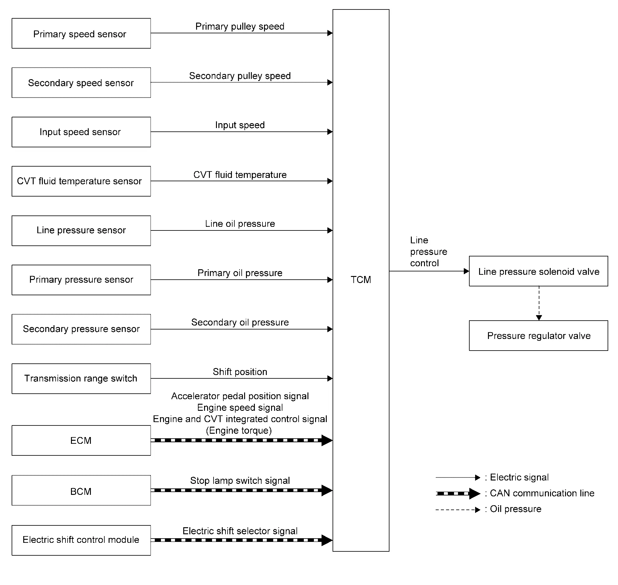
DESCRIPTION
Highly accurate line pressure control and secondary pressure control reduces friction for improvement of fuel economy.
Normal Oil Pressure Control
Appropriate line pressure and secondary pressure suitable for driving condition are determined based on the accelerator pedal position, engine speed, primary pulley (input) speed, secondary pulley (output) speed, Nissan Ariya vehicle speed, input torque, stop lamp switch signal, transmission range switch signal, lock-up signal, power voltage, target shift ratio, oil temperature, oil pressure, and manual mode signal.
Secondary Pressure Feedback Control
In normal oil pressure control and oil pressure control in shifting, highly accurate secondary pressure is determined by detecting the secondary pressure using an oil pressure sensor and by feedback control.
Shift Control
System Description
SYSTEM DIAGRAM
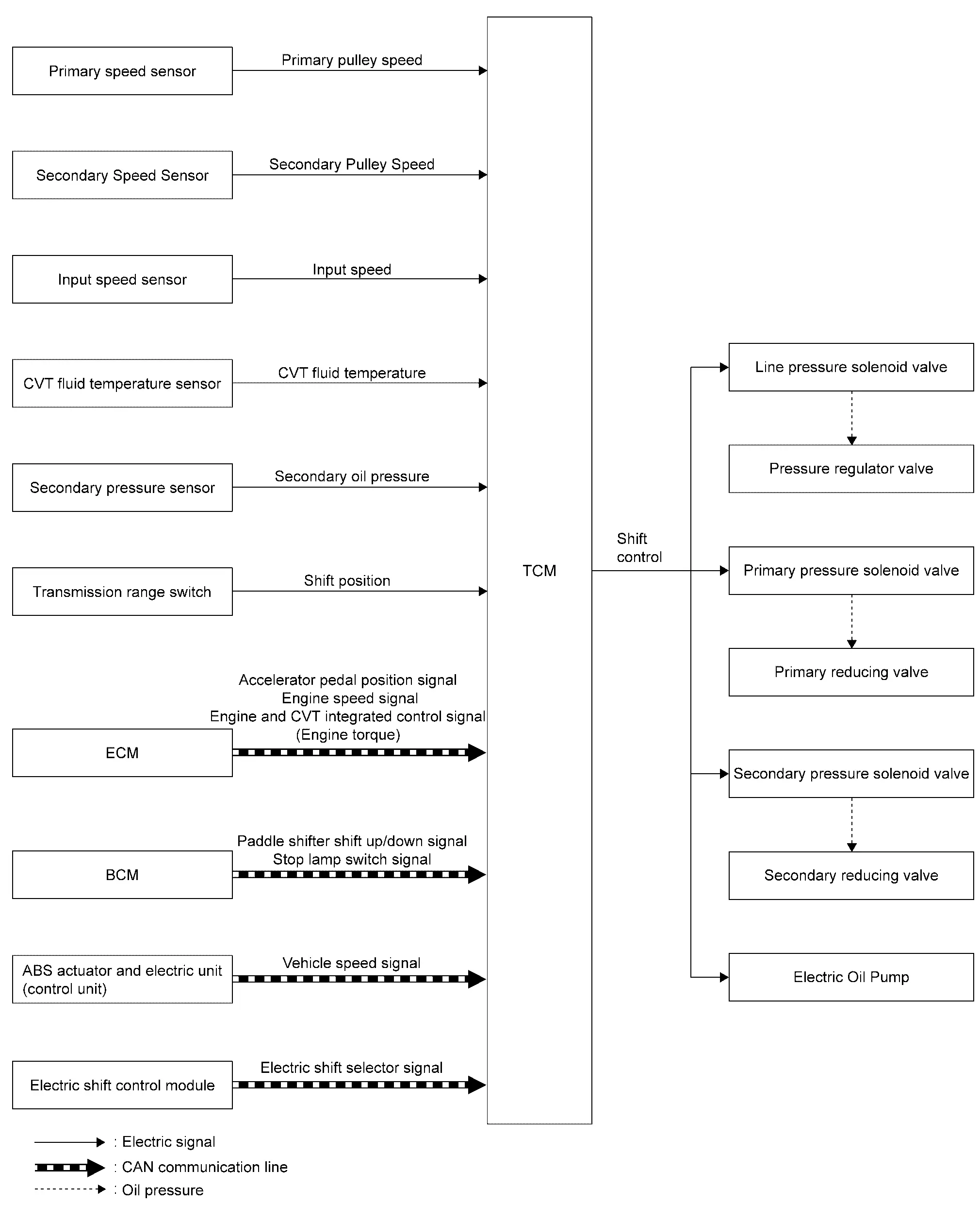
DESCRIPTION
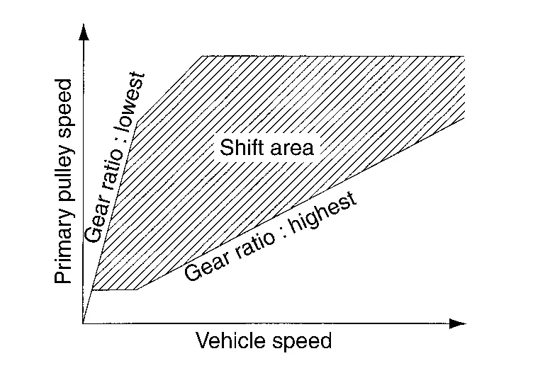
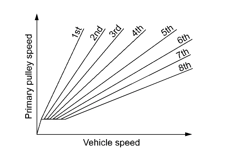
To select the gear ratio that can give the driving force to meet driver's intent or vehicle situation, the Nissan Ariya vehicle driving condition such as vehicle speed or accelerator pedal position is detected and the most appropriate gear ratio is selected and the shifting method before reaching the speed is determined. The information is output to the primary pressure solenoid valve and secondary pressure solenoid valve to control the line pressure input/output to the pulley, to determine the pulley (movable pulley) position and to control the gear position.
Shift Position Function
D Position
Gear shifting is performed in all shifting ranges from the lowest to the highest gear ratio.
M Position (Manual Mode)
By moving the paddle shifter to + side or - side, the manual mode switch is changed over, and shift change like M/T becomes possible following the changing gear set line step by step.
Manual Mode Information
-
The TCM transmits the manual mode shift refusal signal to the combination meter if the TCM refuses the transmission from the driving status of Nissan Ariya vehicle when the paddle shifter shifts to UP side (+ side) or DOWN side (ŌłÆside). The combination meter blinks shift indicator on the combination meter and sounds the buzzer to indicate the driver that the shifting is not performed when receiving this signal. However, the TCM does not transmit the manual mode shift refusal signal in the conditions as per the following.
-
When the paddle shifter shifts to DOWN side (ŌłÆ side) while driving in M1.
-
When the paddle shifter shifts to UP (+ side) side while driving in M8.
-
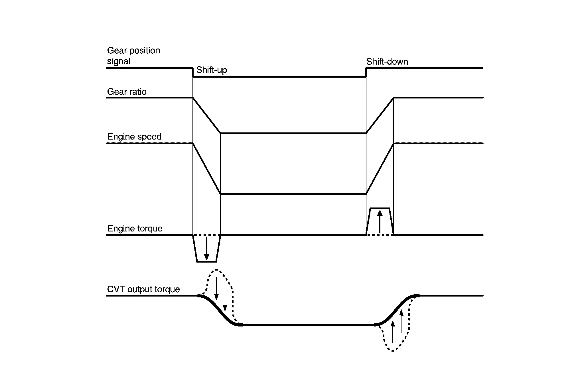
Blipping Control
Using engine torque, the blipping control enables a faster and more responsive gear shifting by compensating inertia torque generated from the rotational change during gear shifting in real time.
Operation
-
The blipping control is activated when shifting up/down in manual mode.
-
TCM selects blipping control or normal shift control according to the gear position, the shift position, etc.
-
The blipping control is activated when ECM judges it controllable after receiving a control permit signal and request torque signal based on generated inertia torque from TCM.
-
ECM controls engine torque, based on request torque from TCM.
Hill Climbing And Descending Control
If a downhill is detected with the accelerator pedal is released, the system performs downshift to increase the engine brake force so that Nissan Ariya vehicle may not be accelerated more than necessary. If a climbing hill is detected, the system improves the acceleration performance in re-acceleration by limiting the gear shift range on the high side.
 NOTE:
NOTE:
For engine brake control on a downhill, the control can be stopped with CONSULT.

Control In Acceleration
From change of the vehicle speed or accelerator pedal position, the acceleration request level of the driver or driving scene is evaluated. In start or acceleration during driving, the gear shift characteristics with linearity of revolution increase and Nissan Ariya vehicle speed increase are gained to improve the acceleration feel.
Select Control
System Description
SYSTEM DIAGRAM
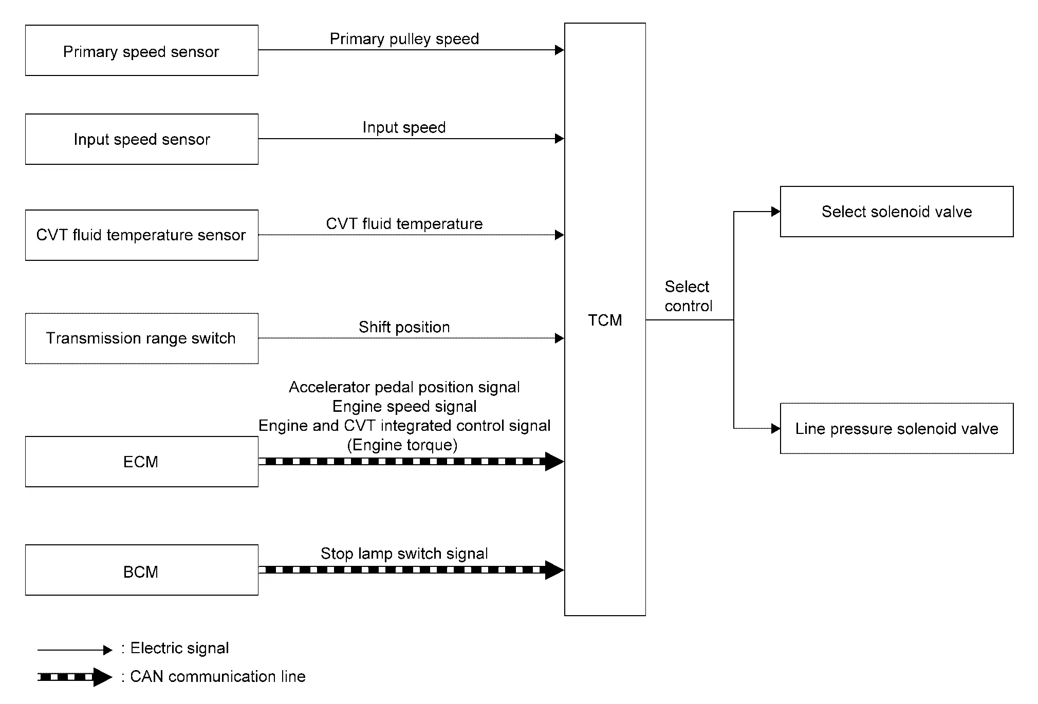
DESCRIPTION
Based on accelerator pedal angle, engine speed, primary pulley speed, and the input speed, the optimum operating pressure is set to reduce impact of a shift operation while shifting from ŌĆ£NŌĆØ (ŌĆ£PŌĆØ) to ŌĆ£DŌĆØ (ŌĆ£RŌĆØ) position.
Lock-Up Control
System Description
SYSTEM DIAGRAM
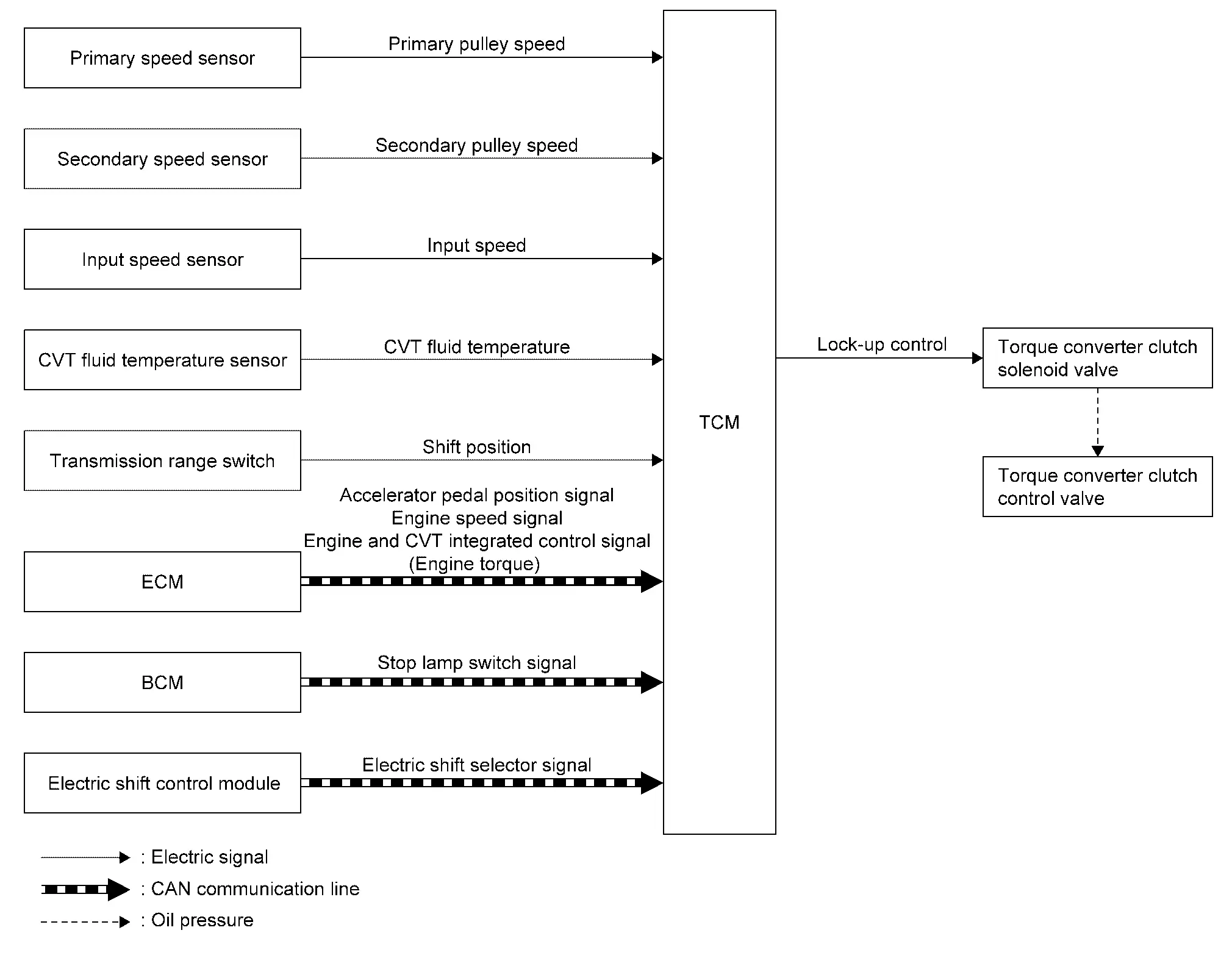
DESCRIPTION
-
Controls for improvement of the transmission efficiency by engaging the torque converter clutch in the torque converter and eliminating slip of the converter. Achieves comfortable driving with slip control of the torque converter clutch.
-
The oil pressure feed circuit for the torque converter clutch piston chamber is connected to the torque converter clutch control valve. The torque converter clutch control valve is switched by the torque converter clutch solenoid valve with the signal from TCM. This controls the oil pressure circuit, which is supplied to the torque converter clutch piston chamber, to the release side or engagement side.
-
If the CVT fluid temperature is low or the Nissan Ariya vehicle is in fail-safe mode due to malfunction, lock-up control is prohibited.
Lock-up engagement
In lock-up engagement, the torque converter clutch solenoid valve makes the torque converter clutch control valve locked up to generate the lock-up apply pressure. This pushes the torque converter clutch piston for engagement.
Lock-up release condition
In lock-up release, the torque converter clutch solenoid valve makes the torque converter clutch control valve non-locked up to drain the lock-up apply pressure. This does not engage the torque converter clutch piston.
Drive Mode Selector
System Description
DESCRIPTION
TCM controls shift characteristics of transaxle suitable for SPORT mode and ECO mode.
Control Details of Each Mode
| Control item | Control |
|---|---|
| SPORT mode | This mode uses a shift schedule that mainly utilizes the high engine speed zone and improves the driving control characteristic and response. This assists driving that is similar to driving a sports car. |
| ECO mode | This mode uses a shift schedule that prioritizes fuel efficiency by keepingthe low engine speed. |
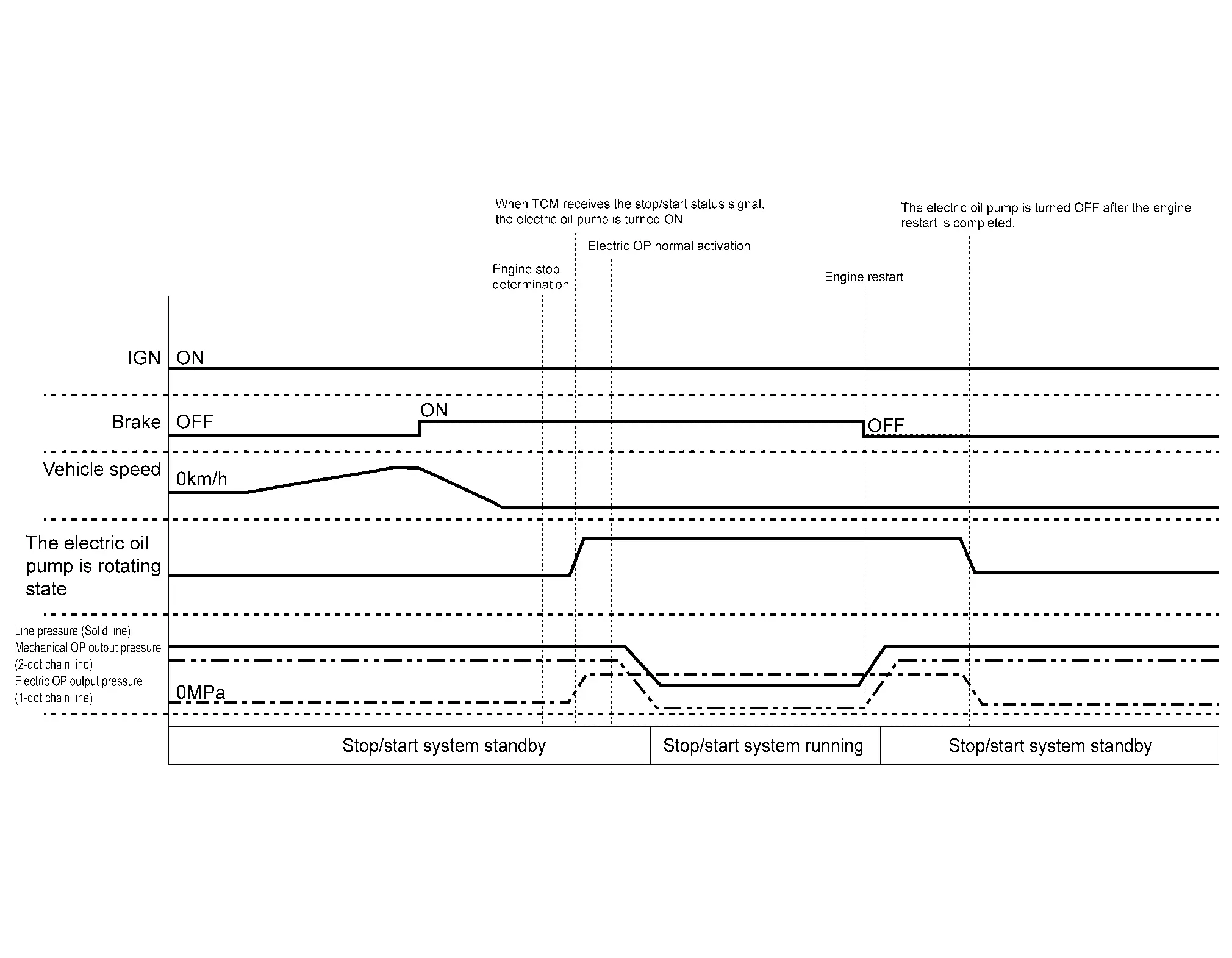
Stop/start System
System Description
STOP/START OPERATION PERMISSION CONDITION EVALUATED BY TCM
When TCM detects the vehicle status and stop/start system operation OK is determined, stop/start enable signal is sent to ECM through CAN communication.
| Item | Description | Permission conditions |
|---|---|---|
| CVT fluid temperature sensor | CVT fluid temperature | 20 ŌĆō 110 ┬░C (68 ŌĆō 230 ┬░F) |
| Electric oil pump | Malfunction | Normal |
| Pully ratio | ŌĆö | 1.3 or more |
TIME CHART
Electric Shift System
System Description
-
The electric shift system detects each shift position electrically. In addition, in P position, the electric shift system activates the shift actuator, according to electrical signals received from the P position switch and brings the Nissan Ariya vehicle into the parking state.
-
In the event of a malfunction in the electric shift system, the selector indicator of electric shift selector turns OFF and only the shift indicator (on the combination meter) indicates the shift position.
-
In the event of a malfunction in the electric shift system, the system enters fail-safe mode. Refer to Fail-safe.
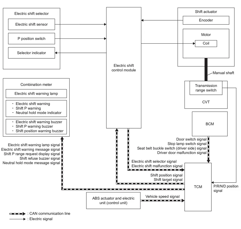
| Component | Function | |
|---|---|---|
| Electric shift control module |
Mainly transmits the following signal to TCM via CAN communication
Mainly receives the following signals from TCM via CAN communication
|
|
| Electric shift selector | Refer to Electric Shift Selector. | |
| Electric shift sensor | Refer to Electric Shift Sensor. | |
| P position switch | Refer to P Position Switch. | |
| Selector indicator | Refer to Selector Indicator. | |
| Shift actuator | Refer to Shift Actuator. | |
| Transmission range switch | Refer to Transmission Range Switch. | |
| TCM |
Mainly transmits the following signal to electric shift control module via CAN communication
Mainly receives the following signals from electric shift control module via CAN communication
|
|
| BCM |
Mainly transmits the following signal to TCM via CAN communication
|
|
| ABS actuator and electric unit (control unit) |
Mainly transmits the following signal to TCM via CAN communication
|
|
| Combination meter |
Mainly receives the following signal from TCM via CAN communication
|
|
Fail-safe
| DTC | Nissan Ariya Vehicle behavior |
|---|---|
| P0604ŌĆō00 |
|
| P0605ŌĆō00 |
|
| P0606ŌĆō00 |
|
| P0607ŌĆō00 |
|
| P060CŌĆō00 |
|
| P062FŌĆō00 |
|
| P0666ŌĆō00 | No impact to Nissan Ariya vehicle behavior |
| P06B1ŌĆō00 | Determination time of the shift selector position becomes long (1 second or more) |
| P072AŌĆō00 |
|
| P0780ŌĆō00 | No impact to Nissan Ariya vehicle behavior |
|
|
| P07E9ŌĆō00 | No impact to Nissan Ariya vehicle behavior |
| P07EAŌĆō00 | No impact to Nissan Ariya vehicle behavior |
| P07EBŌĆō00 | No impact to Nissan Ariya vehicle behavior |
| P07ECŌĆō00 | Determination time of the shift selector position becomes long (1 second or more) |
| P07EDŌĆō00 |
|
| P07EEŌĆō00 |
|
| P07EFŌĆō00 |
|
| P07F2ŌĆō00 |
|
| P0850ŌĆō00 | Pushing the P position switch does not switch to the P position |
| P0851ŌĆō00 | Pushing the P position switch does not switch to the P position |
| P0852ŌĆō00 | Pushing the P position switch does not switch to the P position |
| P0915ŌĆō00 |
|
| P0919ŌĆō00 |
|
| P1894ŌĆō00 | No impact to Nissan Ariya vehicle behavior |
| P189DŌĆō00 | No impact to Nissan Ariya vehicle behavior |
| P18A8ŌĆō00 | Pushing the P position switch does not switch to the P position |
| P18ABŌĆō00 | Automatic P position system may be disabled |
| P18ACŌĆō00 | No impact to Nissan Ariya vehicle behavior |
| P272AŌĆō00 |
|
| P272BŌĆō00 |
|
| U007AŌĆō00 |
|
| U0101ŌĆō00 |
|
| U2118ŌĆō87 | No impact to Nissan Ariya vehicle behavior |
| U2141ŌĆō87 |
|
| U2148ŌĆō87 | No impact to Nissan Ariya vehicle behavior |
| U214FŌĆō87 | No impact to Nissan Ariya vehicle behavior |
| U215BŌĆō87 | No impact to Nissan Ariya vehicle behavior |
*: With stop/start system
Protection Control
If shifting to P/R/N/D position is repeated within a short period of time, it may become impossible to shift for system protection. In this case, the system automatically returns to the normal state allowing shifting after approximately 20 seconds.
Information Display (combination Meter)
CVT System Warning
DESIGN/PURPOSE
CVT Malfunction Warning (Type A)
This warning is displayed when:
-
CVT system/function is not normal. (Case 1)
-
driver door is not normal. (Case 2)
| Design | Warning Message | ||||||
|---|---|---|---|---|---|---|---|
 |
CVT Malfunction Service now |
||||||
CVT Malfunction Warning (Type B)
This warning is displayed when CVT system/function is not normal.
| Design | Warning Message | ||||||
|---|---|---|---|---|---|---|---|
|
CVT Malfunction Stop safety |
||||||
CVT Malfunction Warning (Type C)
This warning is displayed when CVT system/function is not normal.
| Design | Warning Message | ||||||
|---|---|---|---|---|---|---|---|
|
Service CVT Power reduced |
||||||
CVT Hot Warning
This warning is displayed when CVT fluid temperature is high.
| Design | Warning Message | ||||||
|---|---|---|---|---|---|---|---|
|
CVT hot Power reduced |
||||||
CVT Stop The Vehicle Warning
This warning is displayed when CVT system judges the vehicle is reversed on an uphill road with the shift position in D (Drive), or moved forward on a downhill road with the shift position in R (Reverse).
| Design | Warning Message | ||||||
|---|---|---|---|---|---|---|---|
|
Stop the Nissan Ariya vehicle | ||||||
SYNCHRONIZATION WITH MASTER WARNING LAMP
Applicable
SYNCHRONIZATION WITH WARNING BUZZER
Not applicable
OPERATION AT COMBINATION METER CAN COMMUNICATION CUT-OFF OR UNUSUAL SIGNAL
For actions on CAN communications blackout in the combination meter, refer to Fail-Safe.
SYSTEM DIAGRAM
Except CVT System Warning Type A (Case 2)
*: For DTCs that the CVT system warning displays, refer to DTC Index (TCM) and DTC Index (ELECTRIC SHIFT CONTROL MODULE).
CVT System Warning Type A (Case 2)

SIGNAL PATH
Except CVT Malfunction Warning Type A (Case 2)
-
The TCM judges and decides condition of CVT system/function, according to signals received from each sensor/switch, each actuator, and Electric shift control module.
-
When the displaying conditions of the CVT system warning are satisfied, TCM transmits a CVT warning message signal to the combination meter via CAN communication.
-
The combination meter displays the each message according to the CVT warning message signal.
CVT Malfunction Warning Type A (Case 2)
-
BCM transmits a driver door malfunction signal to the TCM when detecting a malfunction of front door switch LH.
-
TCM transmits an CVT warning message signal to the combination meter when receiving the driver door malfunction signal.
-
The combination meter displays the CVT malfunction warning according to the CVT warning message signal.
WARNING CONDITION
CVT Malfunction Warning Type A (Case 1), Type B and Type C
When any of the following conditions are satisfied at ignition ON:
-
CVT system/function malfunction is detected
-
Electric shift system/function malfunction is detected
NOTE:
For DTCs that the CVT system warning displays, refer to DTC Index (TCM) and DTC Index (ELECTRIC SHIFT CONTROL MODULE).
CVT Malfunction Warning Type A (Case 2)
When driver door malfunction signal is detected at ignition ON.
CVT Hot Warning
When CVT fluid temperature becomes high and CVT protection control operates.
Stop The Vehicle Warning
When the CVT system judges the vehicle is reversed on an uphill road with the shift position in D (Drive), or moved forward on a downhill road with the shift position in R (Reverse).
WARNING CANCEL CONDITION
CVT Malfunction Warning Type A (Case 1), Type B and Type C
When any of the following conditions are satisfied.
-
Erase DTC
-
Vehicle speed: Less than the specified vehicle speed [Specific DTC only. Refer to DTC Index (TCM) and DTC Index (ELECTRIC SHIFT CONTROL MODULE)]
CVT Malfunction Warning Type A (Case 2)
When any of the following conditions are satisfied.
-
Driver door malfunction signal are not detected
-
Vehicle speed: Less than the specified Nissan Ariya vehicle speed
CVT Hot Warning
When CVT fluid temperature becomes low and CVT protection control stops.
Stop The Vehicle Warning
When the CVT system does not judge the vehicle is reversed on an uphill road with the shift position in D, or moved forward on a downhill road with the shift position in R.
Shift Position Indicator
PURPOSE
The shift position indicator displays the shift position of transaxle.

SYSTEM DIAGRAM
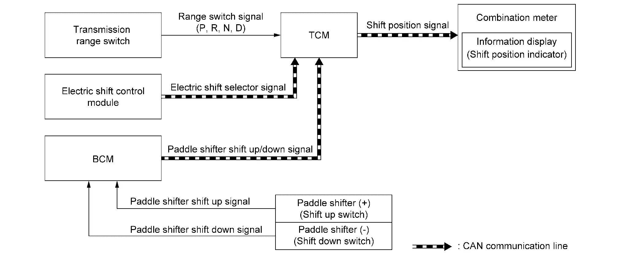
SIGNAL PATH
-
The TCM judges the shift position by the transmission range switch, electric shift selectar signal, and paddle shifter upshift/downshift signal.
-
The TCM transmits the shift position signal to the combination meter via CAN communication. The combination meter shows the shift position indicator on the information display, according to the signal.
Neutral Hold Mode Indicator
DESIGN/PURPOSE
Neutral Hold Mode Guidance Indicator
This indicator displays when the ignition switch is OFF while the shift positionis in the ŌĆ£NŌĆØ (Neutral) position (Neutral hold mode is available).
Neutral Hold Mode Activated Indicator
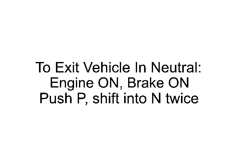
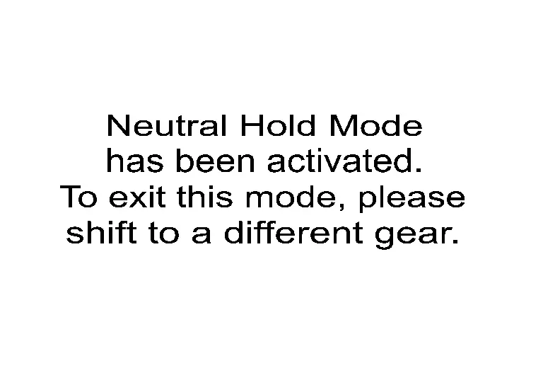
This indicator displays when the neutral hold mode is activated. To exit the neutral hold mode, place the Nissan Ariya vehicle in other than ŌĆ£NŌĆØ (Neutral) position.
Neutral Hold Mode Was Not Activated Indicator
This indicator displays when the neutral hold mode is unavailable. To activate the neutral hold mode, wait for a while without shifting and then perform the operations again.

Electric Shift Warning
DESIGN/PURPOSE
Electric Shift Warning
This warning is displayed when:
-
electric shift system is not normal. (Case 1)
-
driver door is not normal. (Case 2)
Shift Position Warning
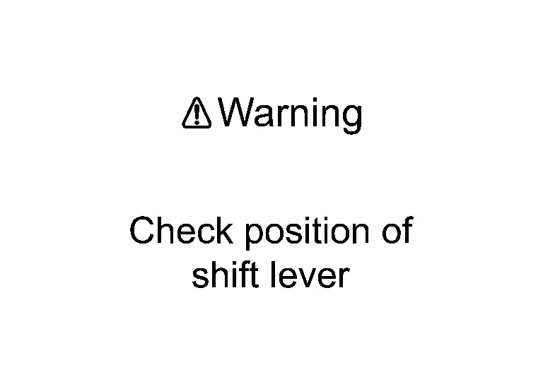
This warning is displayed when the selector lever is in between positions.
SYNCHRONIZATION WITH MASTER WARNING LAMP
Applicable
SYNCHRONIZATION WITH WARNING BUZZER
Applicable
For warning buzzer, refer to Electric Shift Warning (Buzzer).
OPERATION AT COMBINATION METER CAN COMMUNICATION CUT-OFF OR UNUSUAL SIGNAL
For actions on CAN communications blackout in the combination meter, refer to Fail-Safe.
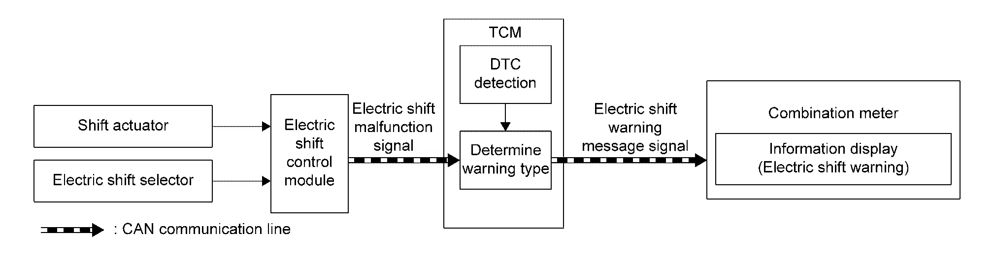
SYSTEM DIAGRAM
Except Electric Shift Warning (Case 2)
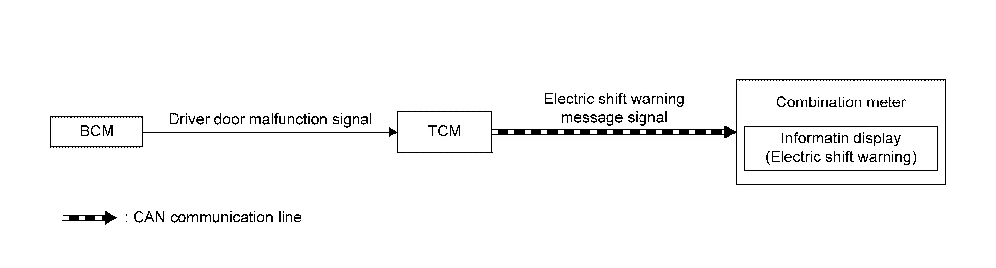
Electric Shift Warning (Case 2)
SIGNAL PATH
Except Electric Shift Warning (Case 2)
-
The electric shift control module transmits an electric shift malfunction signal to the TCM when detecting a malfunction in the electric shift system.
-
TCM detects DTC when TCM receives an electric shift malfunction signal.
-
TCM transmits an electric shift warning message signal to the combination meter when detecting DTC in TCM.
-
The combination meter displays the each message according to the electric shift warning message signal.
Electric Shift Warning (Case 2)
-
BCM transmits a driver door malfunction signal to the TCM when detecting a malfunction of front door switch LH.
-
TCM transmits an electric shift warning message signal to the combination meter when receiving the driver door malfunction signal.
-
The combination meter displays the electric shift warning according to the electric shift warning message signal.
WARNING CONDITION
Electric Shift Warning (Case 1)
When all of the following conditions are satisfied at ignition ON:
-
Parking brake is not applied
-
Vehicle speed: Less than the specified vehicle speed
-
When a malfunction is detected in the CVT system/function and/or electric shift system/function
NOTE:
For DTCs that the electric shift warning displays, refer to DTC Index (TCM) and DTC Index (ELECTRIC SHIFT CONTROL MODULE).
When all of the following conditions are satisfied at ignition OFF:
-
Except neutral hold mode
-
Shift position: Except P position
-
Parking brake is not applied
-
When a malfunction is detected in the CVT system/function and/or electric shift system/function
NOTE:
For DTCs that the electric shift warning displays, refer to DTC Index (TCM) and DTC Index (ELECTRIC SHIFT CONTROL MODULE).
Electric Shift Warning (Case 2)
When all of the following conditions are satisfied at ignition ON:
-
Parking brake is not applied
-
Vehicle speed: Less than the specified vehicle speed
-
Driver door malfunction signal is detected
Shift Position Warning
When selector lever is in between positions for 1 second.
WARNING CANCEL CONDITION
Electric Shift Warning (Case 1)
When any of the following conditions are satisfied.
-
After operating the parking brake with the ignition ON, turn OFF the ignition switch.
-
Erase DTC
-
Nissan Ariya Vehicle speed: The specified vehicle speed or more
Electric Shift Warning (Case 2)
When any of the following conditions are satisfied.
-
After operating the parking brake with the ignition ON, turn OFF the ignition switch.
-
Driver door malfunction signal are not detected
-
Nissan Ariya Vehicle speed: The specified vehicle speed or more
Shift Position Warning
Optimizing selector lever position
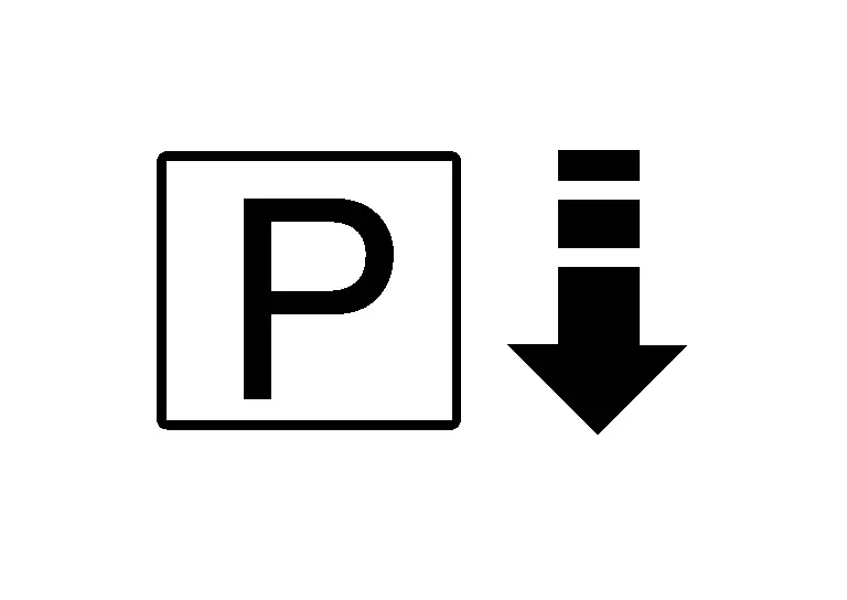
Shift P Warning
DESIGN/PURPOSE
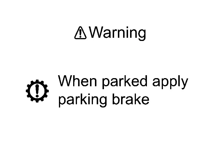
Shift P warning warns that the driver is getting off the vehicle with the shift position not in P position.
| Symbol | Message |
|---|---|
|
|
Shift to P range |
SYNCHRONIZATION WITH MASTER WARNING LAMP
Applicable
SYNCHRONIZATION WITH WARNING (Buzzer)
Applicable
For warning chime, refer to Shift P Warning (Buzzer).
OPERATION AT COMBINATION METER CAN COMMUNICATION CUT-OFF OR UNUSUAL SIGNAL
For actions on CAN communications blackout in the combination meter, refer to Fail-Safe.
SYSTEM DIAGRAM
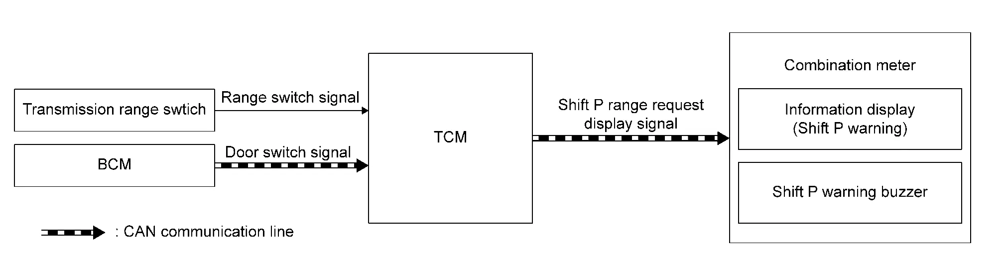
SIGNAL PATH
-
TCM judges the shift position by the transmission range switch.
-
BCM transmits a door switch signal to the TCM.
-
The TCM judges the Nissan Ariya vehicle condition according to the shift position signal and the door switch signal. The TCM transmits a shift P range request display signal to the combination meter if the driverŌĆÖs door is opened with the shift position not in P position.
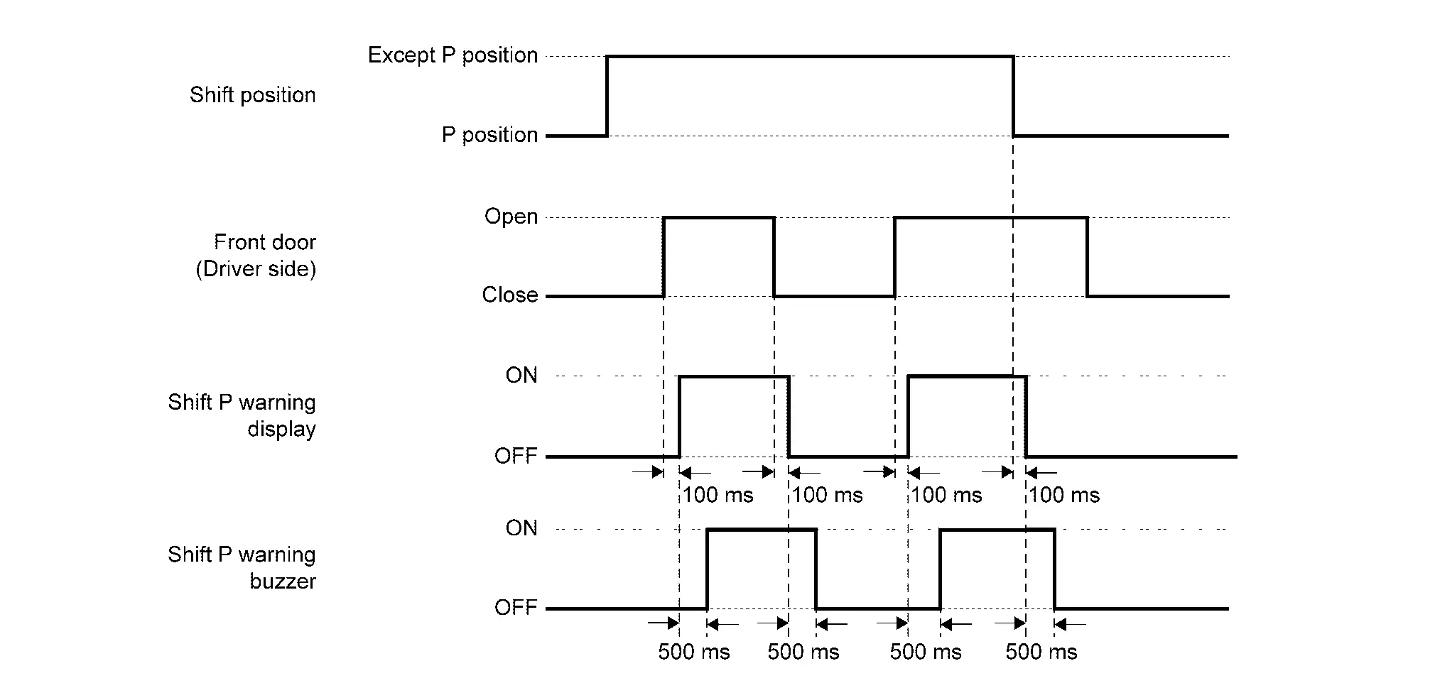
WARNING/INDICATOR OPERATING CONDITION
When all of the following conditions are satisfied:
-
Shift position: Except P position
-
Front door (driver side): Open
WARNING/INDICATOR CANCEL CONDITION
When any of the following conditions are satisfied:
-
Shift position: P position
-
Front door (driver side): Close
TIMING CHART
Warning/indicator/chime List
Warning Lamp/Indicator Lamp
| Item | Design | Layout / Function |
|---|---|---|
| Electric shift warning lamp |  |
For layout, refer to Design. |
| For function, refer to Electric Shift Warning Lamp (Full TFT meter) or Electric Shift Warning Lamp (7 inch information display). | ||
| Malfunction indicator lamp (MIL) |  |
Regarding the function. Refer to Malfunction Indicator Lamp (MIL) (Full TFT meter) or Malfunction Indicator Lamp (MIL) (7 inch information display). |
Warning/Indicator (On Information Display)
| Item | Function |
|---|---|
| CVT system warning | Refer to CVT system warning. |
| Electric shift warning | Refer to Electric Shift Warning. |
| Shift P Warning | Refer to Shift P Warning. |
| Shift position indicator | Refer to Shift position indicator. |
| Neutral hold mode indicator | Refer to Neutral hold mode indicator. |
Warning Chime
| Item | Function |
|---|---|
| Shift position warning (Buzzer) | Refer to Shift Position Warning (Buzzer). |
| Shift P warning (Buzzer) | Refer to Shift P Warning (Buzzer). |
Other materials:
Poste de conduite
Cette vue dŌĆÖensemble du poste de conduite du Nissan Rogue vous aide ├Ā rep├®rer rapidement les commandes essentielles, que vous conduisiez en ville ou sur autoroute. Selon la finition de votre Nissan Rogue, certaines fonctions peuvent ├¬tre pr├®sentes (signal├®es par *), notamment ProPILOT Assist ...
System Description. Component Parts
Body Control System
Component Parts Location
A.
Underneath instrument panel LH (view with lower instrument panel finisher removed)
No. Component Function
1.
BCM
Refer to System Description.
Power Consumption Control System
Component Parts Location
No. Component Functio ...
Dtc/circuit Diagnosis. Drive Mode Select Switch Circuit
Diagnosis Procedure
CHECK DRIVE MODE SELECT SWITCH SIGNAL CIRCUIT
Ignition switch OFF.
Disconnect drive mode select switch harness connector and BCM harness connector.
Check the continuity between drive mode select switch harness connector and BCM harness connector.
2WD models with ...