Nissan Rogue (T33) 2021-Present Service Manual: Structure and Operation
Transaxle
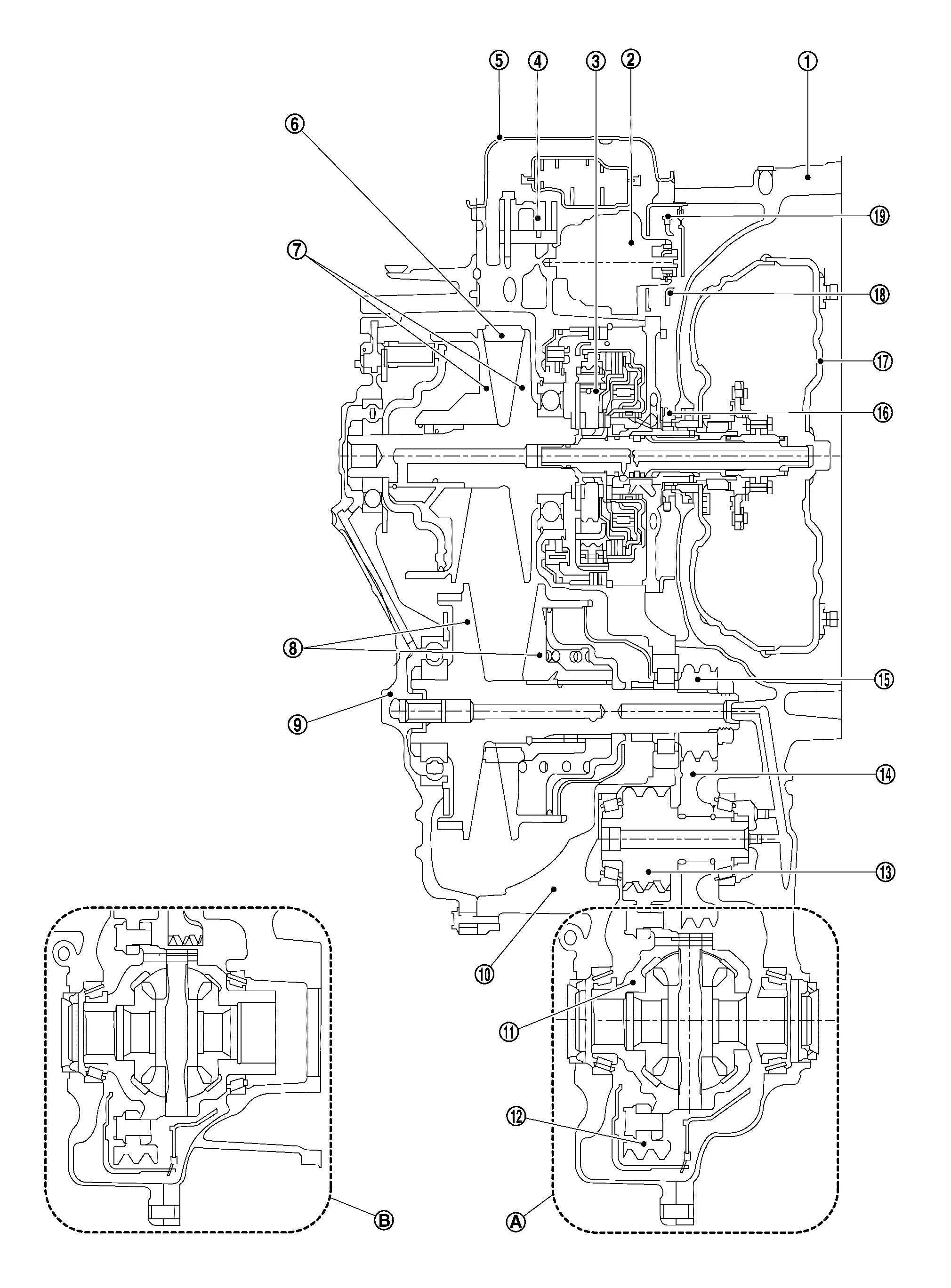
Cross-Sectional View
 |
Converter housing |  |
Oil pump |  |
Planetary gear |
 |
Control valve |  |
Oil pan |  |
Chain belt |
 |
Primary pulley |  |
Secondary pulley |  |
Side cover |
 |
Transaxle case |  |
Differential case |  |
Final gear |
 |
Reduction gear |  |
Idler gear |  |
Output gear |
 |
Drive sprocket |  |
Torque converter |  |
Driven sprocket |
 |
Oil pump chain | ||||
 |
FWD models |  |
AWD models |
Transaxle Mechanism
TORQUE CONVERTER (WITH LOCK-UP FUNCTION)
In the same way as a conventional A/T, the torque converter is a system that increases the engine torque and transmits the torque to the transaxle. A symmetrical 3-element, 1-stage, 2-phase type is used here.
MECHANICAL OIL PUMP
Utilizes a vane-type oil pump that is driven by the engine through the oil pump drive chain in order to increase efficiency of pump discharge volume in low-speed zone and optimize pump discharge volume in high-speed zone. Discharged oil from oil pump is transmitted to control valve. It is used as the oil of primary and secondary pulley operation, the oil of clutch operation, and the lubricant for each part.
ELECTRIC OIL PUMP
Utilizes a vane-type oil pump that is driven by electric energy in order to increase efficiency of pump discharge volume.
This part has two functions as below.
-
Asist mechanical oil pump.
-
Generate oil pressure with control valve and solenoid valve in situation which mechanical oil pump does not operate.
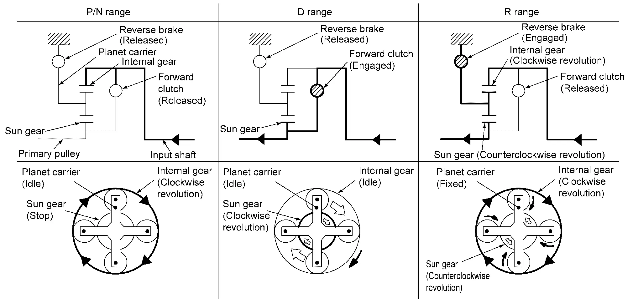
PLANETARY GEAR
-
A planetary gear type of forward/reverse selector mechanism is installed between the torque converter and primary pulley.
-
The power from the torque converter is input via the input shaft, operating a wet multi-plate clutch by means of hydraulic pressure to switch between forward and reverse driving.
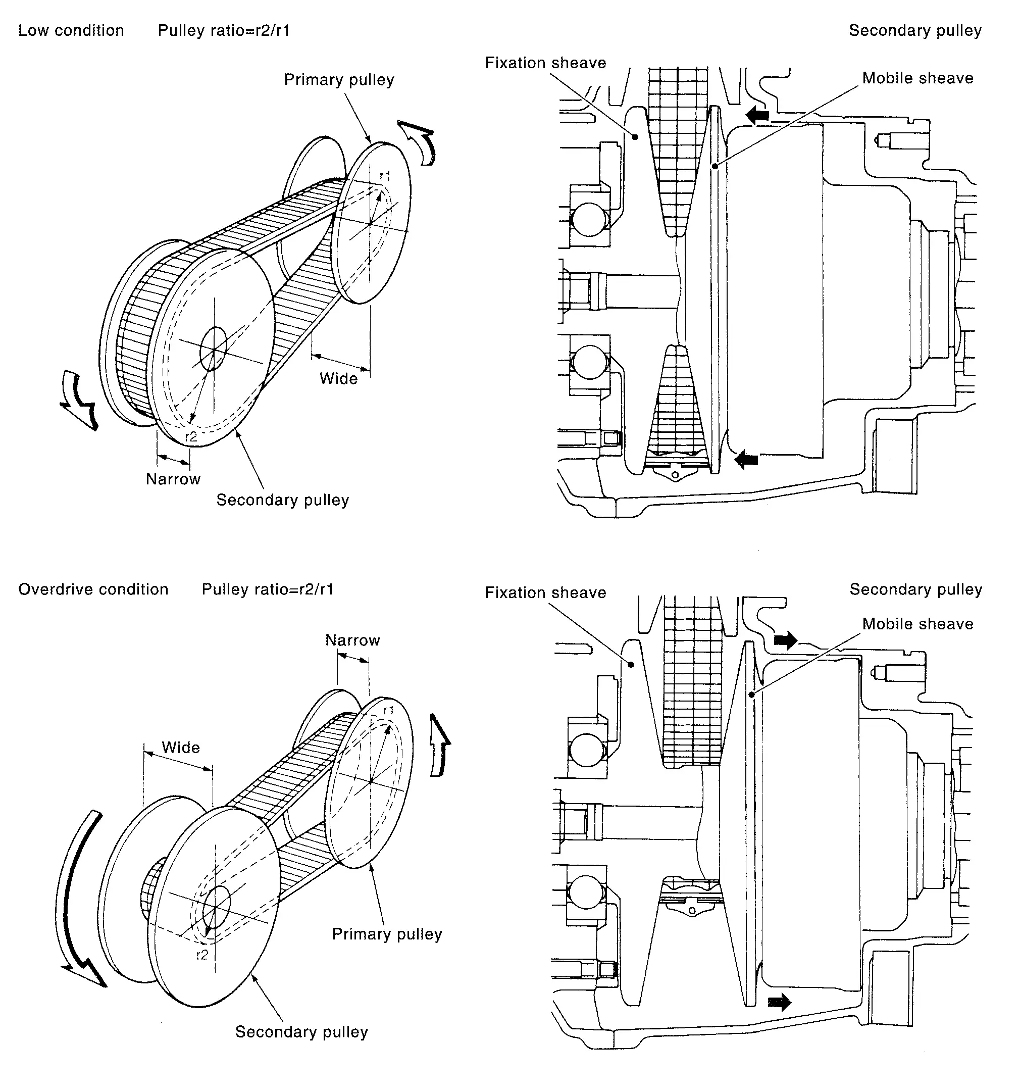
Operation of Planetary gear
It is composed of a pair of pulleys (the groove width is changed freely in the axial direction) and the chain belt .The groove width changes according to wrapping radius of chain belt and pulley from low status to overdrive status continuously with non-step. It is controlled with the oil pressures of primary pulley and secondary pulley.
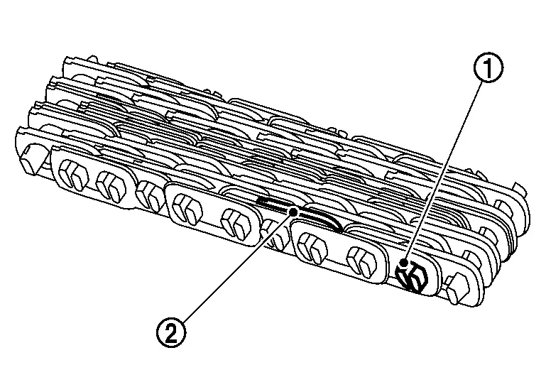
Chain belt
The chain belt consists of approximately 170 locker pins  and 1,000 link plates
  . Chains are rotated by locker pins sandwiched by pulleys. This
produces tension difference in chains among pulleys. Accordingly, the
power is transferred by the tension.
. Chains are rotated by locker pins sandwiched by pulleys. This
produces tension difference in chains among pulleys. Accordingly, the
power is transferred by the tension.
Pulley
The primary pulley (input shaft side) and the secondary pulley (output shaft side) have the shaft with slope (fixed cone surface), movable sheave (movable cone surface that can move in the axial direction) and oil pressure chamber at the back of the movable sheave.
The movable sheave slides on the shaft to change the groove width of the pulley. Input signals of engine load (accelerator pedal opening), primary pulley speed and secondary pulley speed change the operation pressures of the primary pulley and the secondary pulley, and controls the pulley groove width.
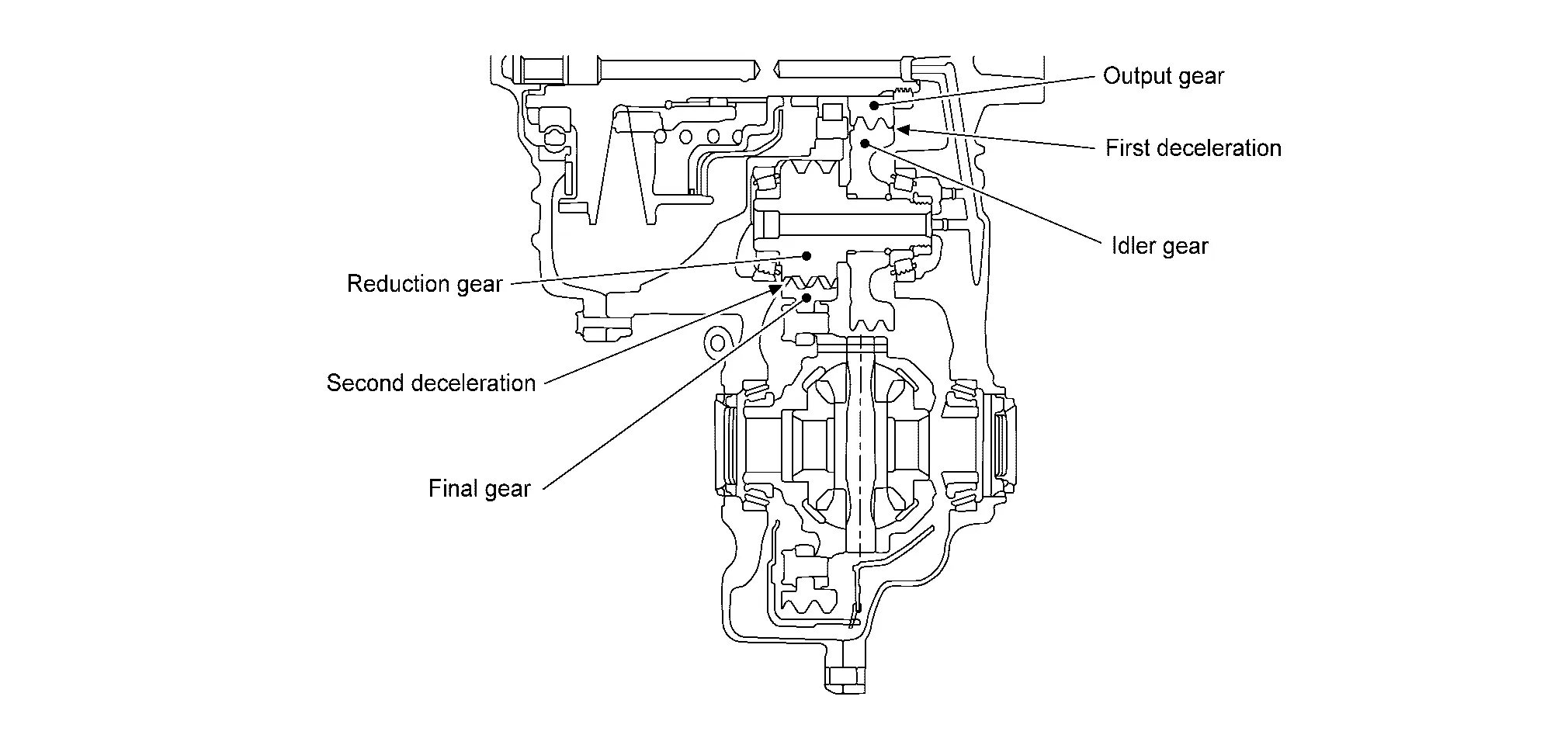
FINAL DRIVE AND DIFFERENTIAL
The deceleration gears are composed of 2 stages: primary deceleration (output gear, idler gear pair) and secondary deceleration (reduction gear, final gear pair). All of these gears are helical gears.
The lubrication oil is the same as the CVT fluid which lubricates the entire transaxle.
Operation Status
├Ś: Engaged or applied.
| Shift position | Parking mechanism | Forward clutch | Reverse brake | Primary pulley | Secondary pulley | Chain belt | Final drive |
|---|---|---|---|---|---|---|---|
| P | ├Ś | ||||||
| R | ├Ś | ├Ś | ├Ś | ├Ś | ├Ś | ||
| N | |||||||
| D/M | ├Ś | ├Ś | ├Ś | ├Ś | ├Ś |
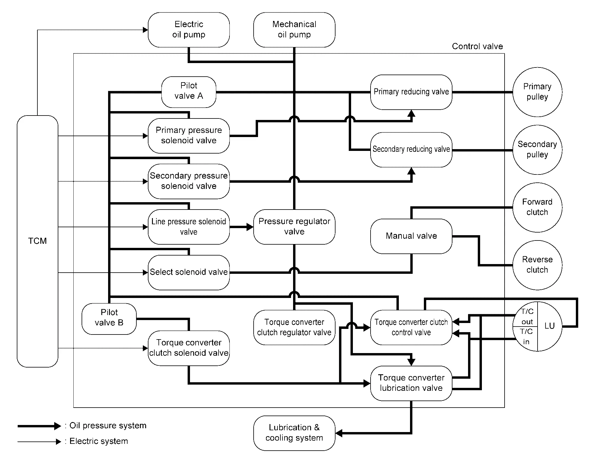
Oil Pressure System
Oil pressure required for operation of the transaxle transmission mechanism is generated by mechanical oil pump, electric oil pump, oil pressure control valve, solenoid valve, etc.
Component Description
| Part name | Function |
|---|---|
| Torque converter | Increases engine torque and transmits it to the transaxle. |
| Mechanical oil pump | Utilizes a vane-type oil pump that is driven by the engine through the oil pump drive chain in order to increase efficiency of pump discharge volume in low-speed zone and optimize pump discharge volume in high-speed zone. Discharged oil from oil pump is transmitted to control valve. It is used as the oil of primary and secondary pulley operation, the oil of clutch operation, and the lubricant for each part. |
| Electric oil pump |
Utilizes a vane-type oil pump that is driven by electric energy in order to increase efficiency of pump discharge volume. This part has two functions as below.
|
| Forward clutch | The forward clutch is wet and multiple plate type clutch that consists of clutch drum, piston, drive plate, and driven plate. It is a clutch to move the Nissan Ariya vehicle forward by activating piston hydraulically, engaging plates, and directly connecting sun gear and input shaft. |
| Reverse brake | The reverse brake is a wet multiple-plate type brake that consists of transaxle case, piston, drive plate, and driven plate. It is a brake to move the Nissan Ariya vehicle in reverse by activating piston hydraulically, engaging plates, and fixing planetary gear. |
| Internal gear | The internal gear is directly connected to forward clutch drum. It is a gear that moves the outer edge of pinion planet of planet carrier. It transmits power to move the Nissan Ariya vehicle in reverse when the planet carrier is fixed. |
| Planet carrier | Composed of a carrier, pinion planet, and pinion shaft. This gear fixes and releases the planet carrier in order to switch between forward and reverse driving. |
| Sun gear | Sun gear is a set part with planet carrier and internal gear. It transmits transmitted force to primary fixed sheave. It rotates in forward or reverse direction according to activation of either forward clutch or reverse brake. |
| Input shaft | The input shaft is directly connected to forward clutch drum and transmits traction force from torque converter. In shaft center, there are holes for hydraulic distribution to primary pulley and hydraulic distribution for lockup ON/OFF. |
| Primary pulley | It is composed of a pair of pulleys (the groove width is changed freely in the axial direction) and the chain belt. The groove width changes according to wrapping radius of chain belt and pulley from low status to overdrive status continuously with non-step. It is controlled with the oil pressures of primary pulley and secondary pulley. |
| Secondary pulley | |
| Chain belt | |
| Manual shaft | When the manual shaft is in the P position, the parking rod that is linked to the manual shaft rotates the parking pole. When the parking pole rotates, it engages with the parking gear, fixing the parking gear. As a result, the secondary pulley that is integrated with the parking gear is fixed. |
| Parking rod | |
| Parking pawl | |
| Parking gear | |
| Output gear | The deceleration gears are composed of 2 stages: primary deceleration (output gear, idler gear pair) and secondary deceleration (reduction gear, final gear pair). All of these gears are helical gears. |
| Idler gear | |
| Reduction gear | |
| Differential | |
| Torque converter clutch regulator valve | Adjusts the feed pressure to the torque converter to the optimum pressure corresponding to the driving condition. |
| Pressure regulator valve | Adjusts the discharge pressure from the oil pump to the optimum pressure (line pressure) corresponding to the driving condition. |
| Torque converter clutch control valve | Adjusts the torque converter engage and disengage pressures. |
| Manual valve | Distributes the clutch operation pressure to each circuit according to the shift position. |
| Secondary reducing valve | Reduces line pressure and adjusts secondary pressure. |
| Primary reducing valve | Reduces line pressure and adjusts primary pressure. |
| Pilot valve A |
Reduces line pressure and adjusts pilot pressure to the solenoid valves listed below.
|
| Pilot valve B | Reduces pilot pressure and adjusts pilot pressure to the torque converter clutch solenoid valve. |
| Primary pressure solenoid valve | Reduces pilot A pressure and adjusts solenoid pressure. |
| Secondary pressure solenoid valve | |
| Line pressure solenoid valve | |
| Select solenoid valve | |
| Torque converter clutch solenoid valve | Reduces pilot B pressure and adjusts solenoid pressure. |
| Torque converterŃĆĆlubrication valve | Switch lubrication circuit and supply lubrication flow to lubrication & cooling system. |
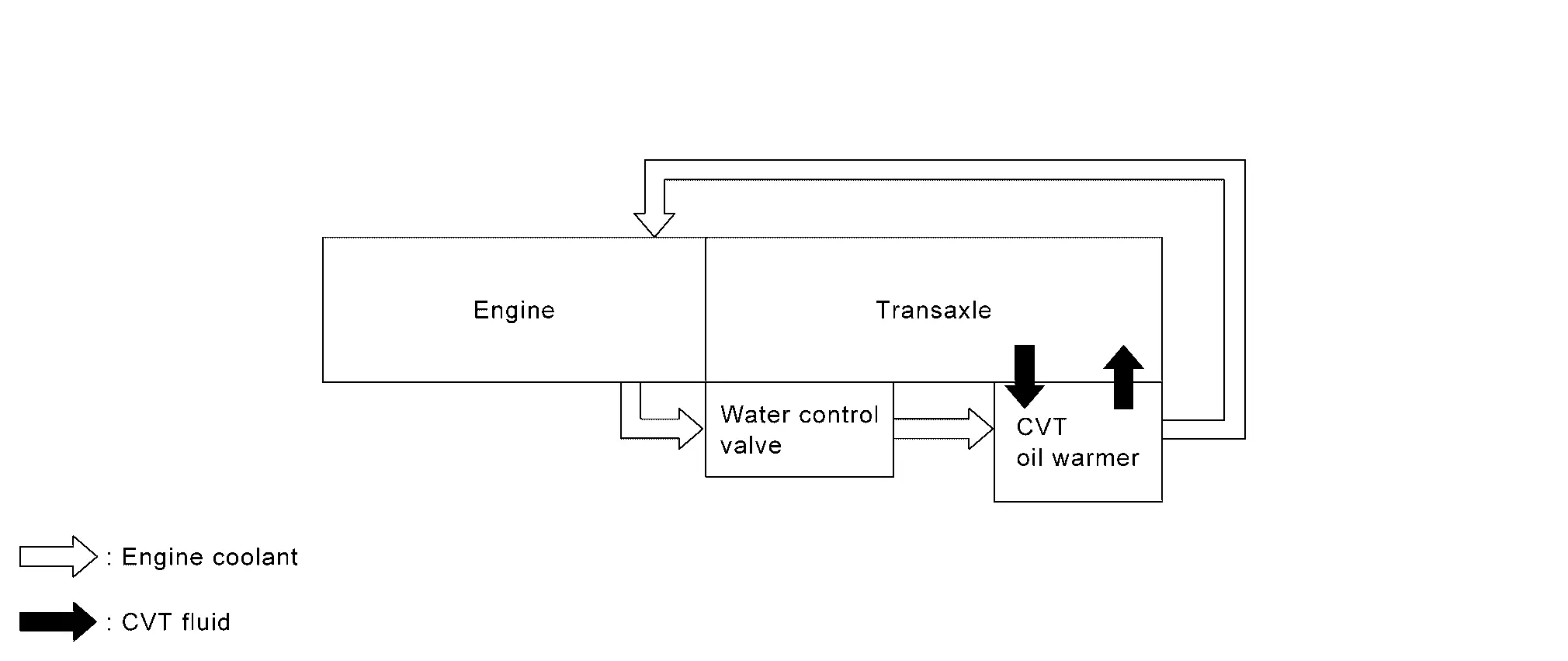
Fluid Cooler System
System Description
CVT FLUID COOLER SCHEMATIC
COMPONENT DESCRIPTION
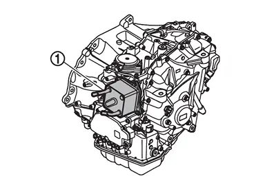
CVT Oil Warmer
-
The CVT oil warmer
is installed on the front part of transaxle assembly. -
When engine is started while engine and CVT are cold, engine coolant temperature rises more quickly than CVT fluid temperature. CVT oil warmer is provided with two circuits for CVT and engine coolant respectively so that warmed engine coolant warms CVT quickly. This helps shorten CVT warming up time, improving fuel economy.
-
A cooling effect is obtained when CVT fluid temperature is high.
Other materials:
System Description. System. Warning/indicator/chime List
Warning/indicator/chime List
Warning Lamp/Indicator Lamp/Information display
Warning lamp Item Design Reference
Seat belt warning lamp
For layout, refer to Design.
For function, refer to Seat Belt Warning Lamp.
Information display Item Reference
Rear seat belt warning
Ref ...
Precaution. Precautions
Precaution for Supplemental Restraint System (SRS) "AIR BAG" and "SEAT BELT PRE-TENSIONER"
The Supplemental Restraint System such as ŌĆ£AIR BAGŌĆØ and ŌĆ£SEAT BELT
PRE-TENSIONERŌĆØ, used along with a front seat belt, helps to reduce the
risk or severity of injury to the driver and front passeng ...
Its Can Communication 4 Circuit
Diagnosis Procedure
CHECK NETWORK DIAGNOSIS
Check the "Network diagnosis" results from CONSULT to see that the diagnostic CAN communication circuit have no malfunction.
Are the diagnostic CAN communication circuit normal?
YES>>
GO TO 2.
NO>>
Check and repair diagnostic CAN commu ...