Nissan Rogue (T33) 2021-Present Service Manual: Component Parts
Cvt Control System
Component Parts Location
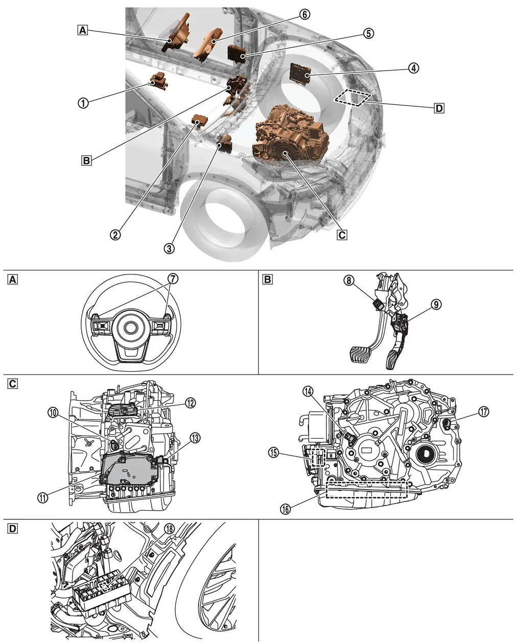
 |
Electric shift selector |  |
Electric shift control module |  |
ABS actuator and electric unit (control unit) Refer to Component Parts Location. |
 |
ECM Refer to Component Parts Location. |
 |
BCM Refer to Component Parts Location. |
 |
Combination meter Refer to Removal and Installation. |
 |
Paddle shifter |  |
Stop lamp switch |  |
Accelerator pedal position |
 |
Input speed sensor |  |
TCM |  |
Electric shift actuator |
 |
CVT unit connector |  |
Primary speed sensor |  |
Electric oil pump |
 |
Control valve |  |
Secondary speed sensor |  |
Shift actuator relay |
 |
Steering wheel |  |
Pedal periphery |  |
Transaxle assembly |
 |
In front of the left front wheel |
TCM
FUNCTIONS WITHIN THE SYSTEM
TCM judges the vehicle driving status based on the signals from the sensors, switches, and other control units, and the optimal transaxle control is performed.
INDIVIDUAL FUNCTION WITHIN SYSTEM
The TCM consists of a microcomputer and connectors for signal input and output and for power supply.
INDIVIDUAL OPERATION
-
CVT control system. Refer to System Description.
-
Line pressure control system. Refer to System Description.
-
Shift control system. Refer to System Description.
-
Select control system. Refer to System Description.
-
Lock-up control system. Refer to System Description.
-
Drive mode selector system. Refer to System Description.
COMPONENT PARTS LOCATION
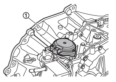
The TCM is installed to the front side of transaxle case.
Transmission Range Switch
FUNCTIONS WITHIN THE SYSTEM
The transmission range switch transfers CVT range position to TCM as voltage signal.
INDIVIDUAL FUNCTION WITHIN SYSTEM
The transmission range switch judges the CVT range position.
INDIVIDUAL OPERATION
Transmission range switch judges the CVT range position by contact point which is switched according to turn of manual shaft.
COMPONENT PARTS LOCATION
The transmission range switch  is installed to control valve.

Input Speed Sensor
FUNCTIONS WITHIN THE SYSTEM
The input speed sensor transfers detected input shaft speed to TCM as pulse signal.
INDIVIDUAL FUNCTION WITHIN SYSTEM
The input speed sensor detects input shaft speed.
INDIVIDUAL OPERATION
The input speed sensor generates an ON-OFF pulse signal according to the rotating body speed.
TCM judges the rotating body speed based on the pulse signal.
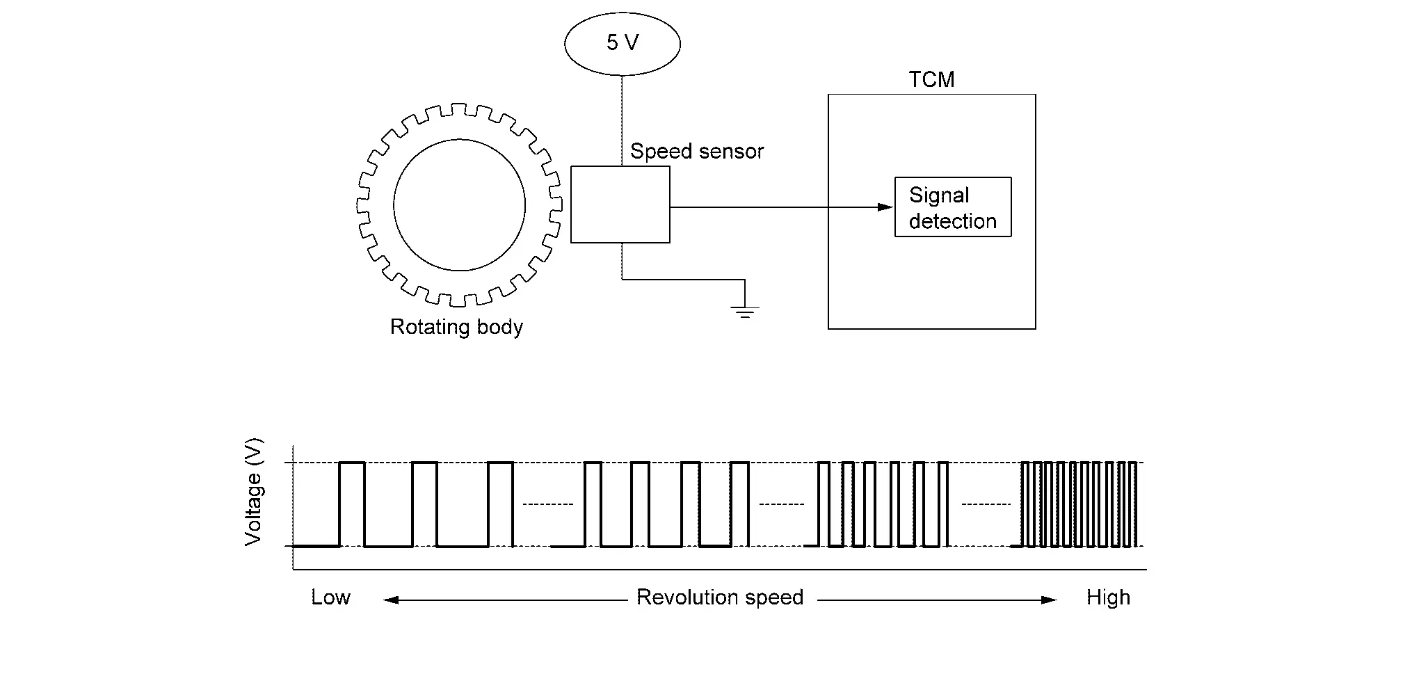
COMPONENT PARTS LOCATION
The input speed sensor is installed to the front side of transaxle case.
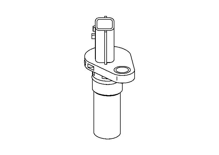
Primary Speed Sensor
FUNCTIONS WITHIN THE SYSTEM
The primary speed sensor transfers detected primary pulley speed to TCM as pulse signal.
INDIVIDUAL FUNCTION WITHIN SYSTEM
The primary speed sensor detects primary pulley speed.
INDIVIDUAL OPERATION
The primary speed sensor generates an ON-OFF pulse signal according to the rotating body speed.
TCM judges the rotating body speed based on the pulse signal.

COMPONENT PARTS LOCATION
The primary speed sensor is installed to transaxle side cover.
Secondary Speed Sensor
FUNCTIONS WITHIN THE SYSTEM
The secondary speed sensor transfers detected secondary pulley speed to TCM as pulse signal.
INDIVIDUAL FUNCTION WITHIN SYSTEM
The secondary speed sensor detects idler gear speed and transfers speed signal to TCM.
TCM calculates secondary pulley speed based on signal from secondary speed sensor.
INDIVIDUAL OPERATION
The secondary speed sensor generates an ON-OFF pulse signal according to the rotating body speed.
TCM judges the rotating body speed based on the pulse signal.
COMPONENT PARTS LOCATION
The secondary speed sensor is installed to rear side to transaxle case.
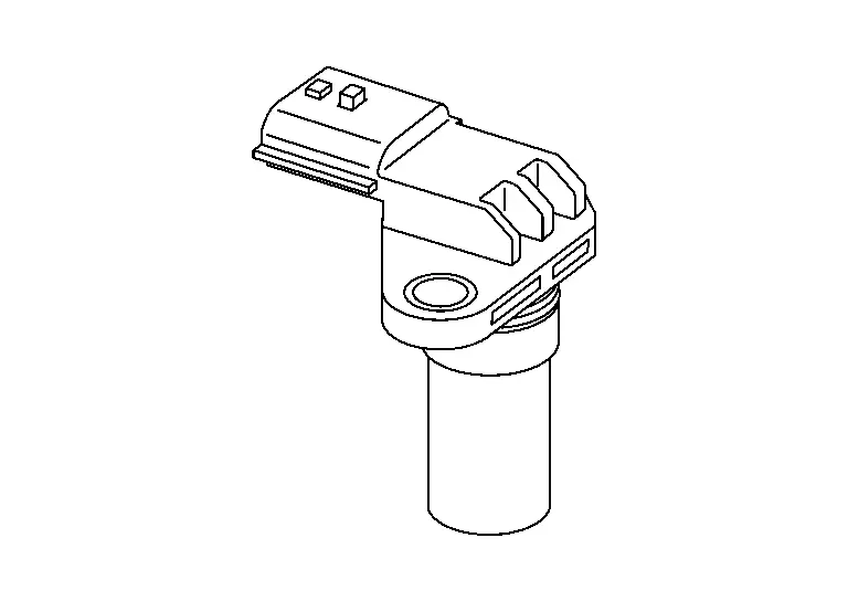
CVT Fluid Temperature Sensor
FUNCTIONS WITHIN THE SYSTEM
The CVT fluid temperature sensor transfers detected fluid temperature to TCM as signal voltage.
INDIVIDUAL FUNCTION WITHIN SYSTEM
The CVT fluid temperature sensor detects CVT fluid temperature in oil pan.
INDIVIDUAL OPERATION
The fluid temperature sensor uses a thermistor, and changes the voltage signal by converting changes in the CVT fluid temperature to a resistance value.
The voltage signal value change must be in proportion to the resistance value change.
TCM evaluates the CVT fluid temperature from the voltage signal value.
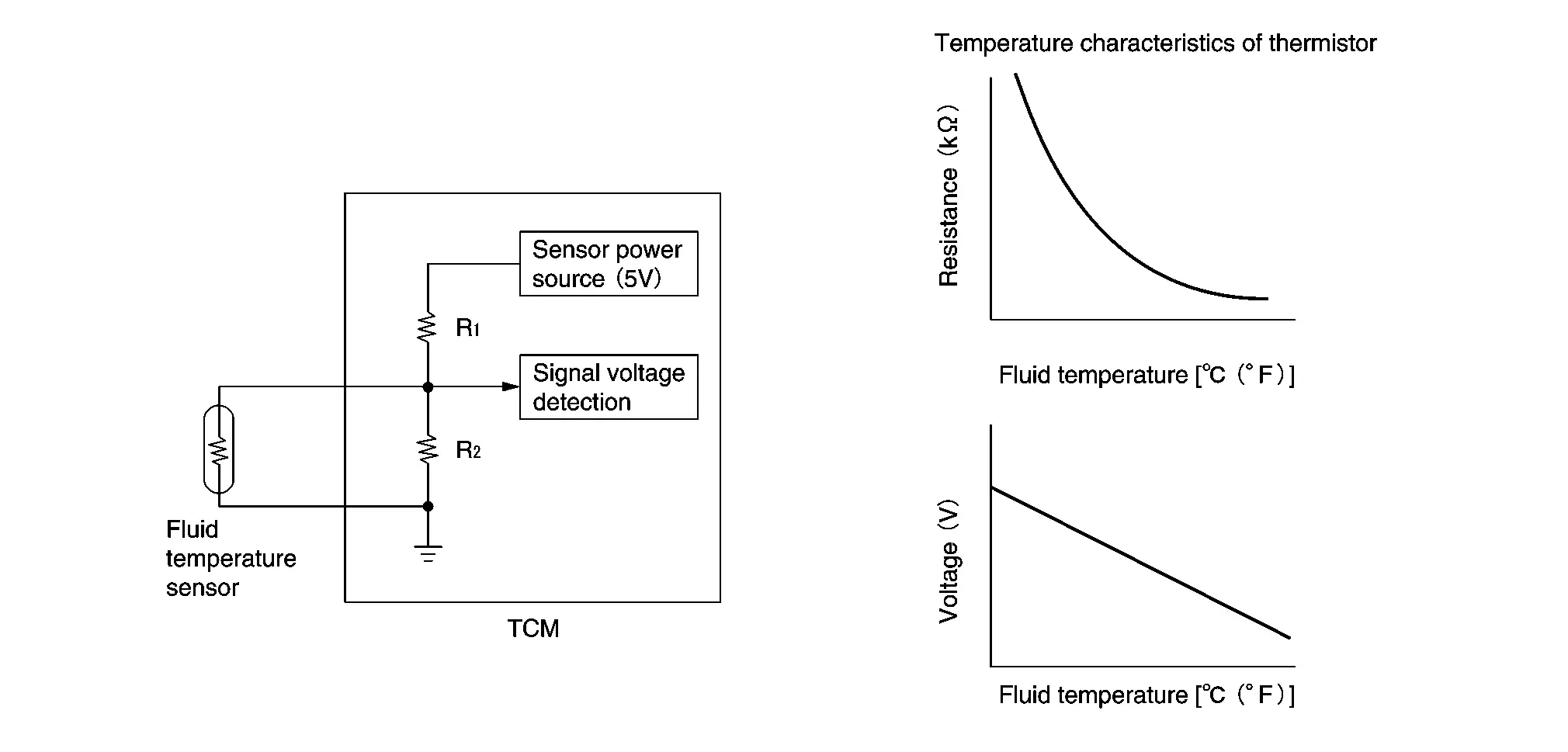
COMPONENT PARTS LOCATION
The CVT fluid temperature sensor is installed to control valve.
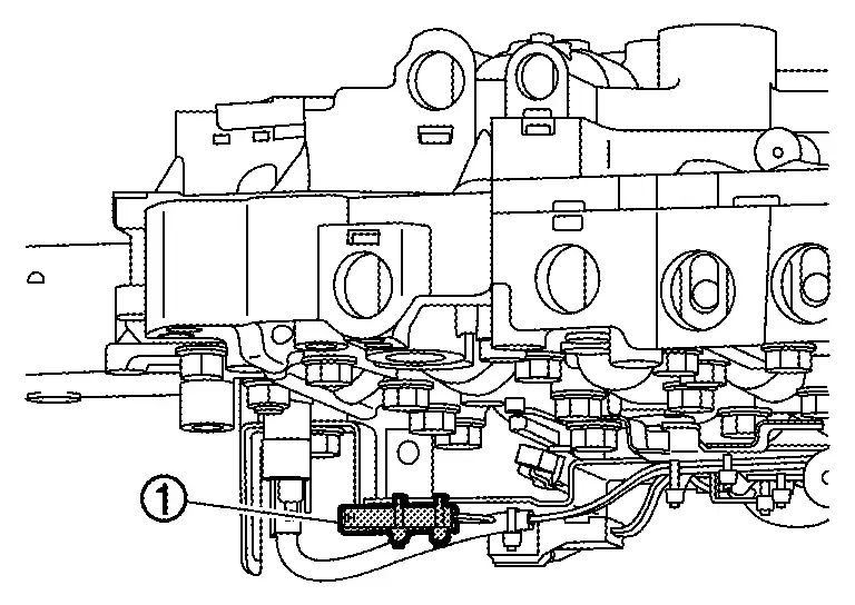
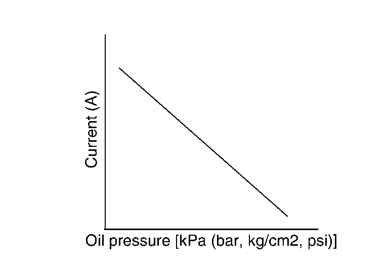
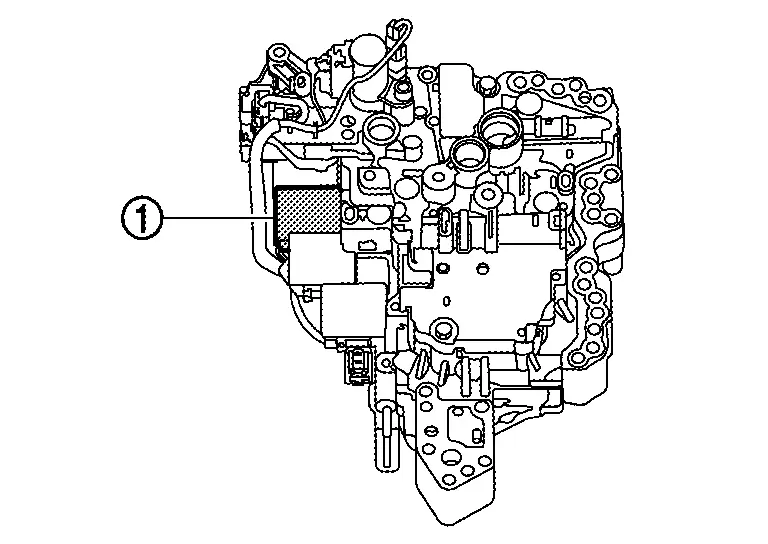
Line Pressure Sensor
FUNCTIONS WITHIN THE SYSTEM
The line pressure sensor transfers detected line pressure to TCM as voltage signal.
INDIVIDUAL FUNCTION WITHIN SYSTEM
The line pressure sensor detects line pressure.
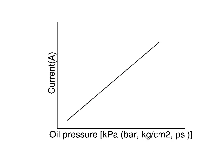
INDIVIDUAL OPERATION
When pressure is applied to the ceramic device in the line pressure sensor, the ceramic device is deformed that produce voltage change.
TCM evaluates the line pressure based on the voltage change.
Voltage is increased along with pressure increase.
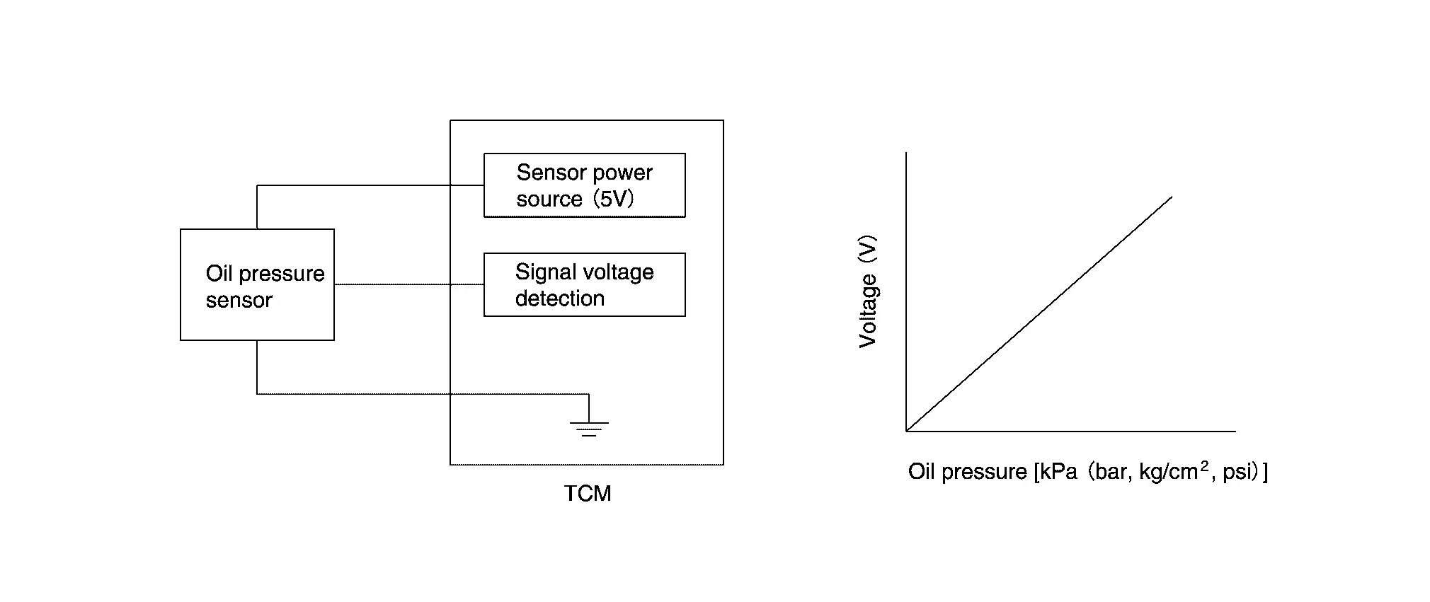
COMPONENT PARTS LOCATION
The line pressure sensor is installed to control valve.
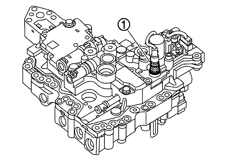
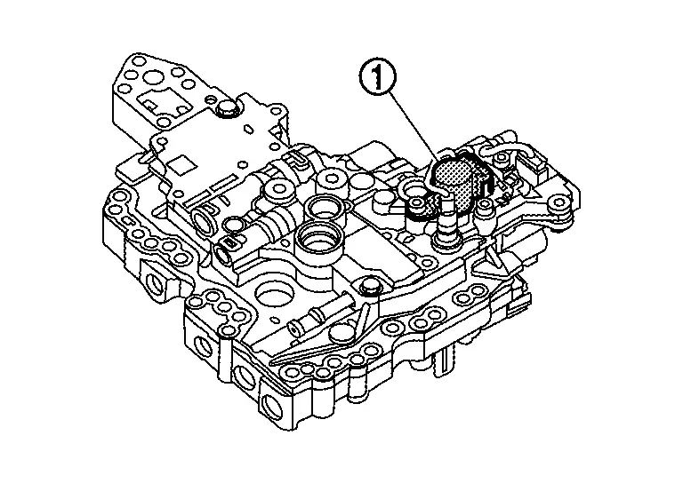
Primary Pressure Sensor
FUNCTIONS WITHIN THE SYSTEM
The primary pressure sensor transfers detected primary pressure to TCM as voltage signal.
INDIVIDUAL FUNCTION WITHIN SYSTEM
The primary pressure sensor detects pressure applied to the primary pulley.
INDIVIDUAL OPERATION
When pressure is applied to the ceramic device in the primary pressure sensor, the ceramic device is deformed that produce voltage change.
TCM evaluates the primary pressure based on the voltage change.
Voltage is increased along with pressure increase.
COMPONENT PARTS LOCATION
The primary pressure sensor is installed to control valve.
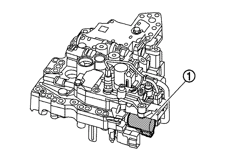
Secondary Pressure Sensor
FUNCTIONS WITHIN THE SYSTEM
The secondary pressure sensor transfers detected secondary pressure to TCM as voltage signal.
INDIVIDUAL FUNCTION WITHIN SYSTEM
The secondary pressure sensor detects pressure applied to the secondary pulley.
INDIVIDUAL OPERATION
When pressure is applied to the ceramic device in the secondary pressure sensor, the ceramic device is deformed that produce voltage change.
TCM evaluates the secondary pressure based on the voltage change.
Voltage is increased along with pressure increase.
COMPONENT PARTS LOCATION
The secondary pressure sensor is installed to control valve.

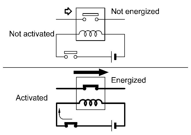
Line Pressure Solenoid Valve
FUNCTIONS WITHIN THE SYSTEM
The line pressure solenoid valve controls the pressure regulator valve by TCM signal, that controls the line pressure.
INDIVIDUAL FUNCTION WITHIN SYSTEM
The line pressure solenoid valve controls the pressure regulator valve.
For information about the pressure regulator valve, refer to Component Description.
INDIVIDUAL OPERATION
The line pressure solenoid valve uses the linear solenoid valve [N/H (normal high) type].
COMPONENT PARTS LOCATION
The line pressure solenoid valve is installed to control valve.
Primary Pressure Solenoid Valve
FUNCTIONS WITHIN THE SYSTEM
The primary pressure solenoid valve controls the primary reducing valve by TCM signal, that controls the primary pressure.
INDIVIDUAL FUNCTION WITHIN SYSTEM
The primary pressure solenoid valve controls the primary reducing valve.
For information about the primary reducing valve, refer to Component Description.
INDIVIDUAL OPERATION
The primary pressure solenoid valve uses the linear solenoid valve [N/H (normal high) type].
COMPONENT PARTS LOCATION
The primary pressure solenoid valve is installed to control valve.
Secondary Pressure Solenoid Valve
FUNCTIONS WITHIN THE SYSTEM
The secondary pressure solenoid valve controls the secondary reducing valve by TCM signal, that controls secondary pressure.
INDIVIDUAL FUNCTION WITHIN SYSTEM
The secondary pressure solenoid valve controls the secondary reducing valve.
For information about the secondary reducing valve, refer to Component Description.
INDIVIDUAL OPERATION
The secondary pressure solenoid valve uses the linear solenoid valve [N/H (normal high) type].
COMPONENT PARTS LOCATION
The secondary pressure solenoid valve is installed to control valve.

Torque Converter Clutch Solenoid Valve
FUNCTIONS WITHIN THE SYSTEM
The torque converter clutch solenoid valve controls the torque converter clutch control valve by TCM signal and adjusts engagement and disengagement pressure of torque converter.
INDIVIDUAL FUNCTION WITHIN SYSTEM
The torque converter clutch solenoid valve controls the torque converter clutch control valve.
For information about the torque converter clutch control valve, refer to Component Description.
INDIVIDUAL OPERATION
The torque converter clutch solenoid valve utilizes a linear solenoid valve [N/L (normal low) type].
COMPONENT PARTS LOCATION
The torque converter clutch solenoid valve is installed to control valve.
Select Solenoid Valve
FUNCTIONS WITHIN THE SYSTEM
The select solenoid valve adjusts the operating pressure of the forward clutch and reverse brake to switch forward/backward movement of Nissan Ariya vehicle.
INDIVIDUAL FUNCTION WITHIN SYSTEM
The select solenoid valve adjusts the operating pressure of the forward clutch and reverse brake.
INDIVIDUAL OPERATION
The select solenoid valve utilizes the linear solenoid valve [N/H (normal high) type].
COMPONENT PARTS LOCATION
The select solenoid valve is installed to control valve.
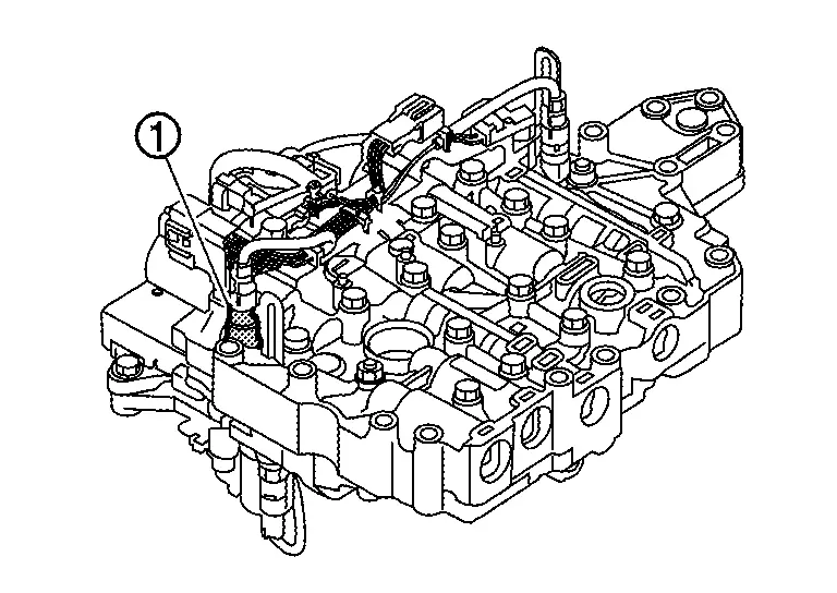
Electric Oil Pump
FUNCTIONS WITHIN THE SYSTEM
Command signal from TCM assists mechanical oil pump built-in transaxle to secure the required fluid pressure.
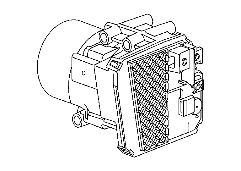
INDIVIDUAL FUNCTION WITHIN SYSTEM
Supply hydraulic pressure according to the request from TCM.
INDIVIDUAL OPERATION
-
Electric oil pump has a built-in brushless three-phase AC motor.
-
Operate by CAN signal from TCM.
-
Transmit the operating status to TCM as a CAN signal.
COMPONENT PARTS LOCATION
The electric oil pump is mounted behind the TCM inside the transaxle assembly.
Paddle Shifter
FUNCTIONS WITHIN THE SYSTEM
The paddle shifter enabled shift operation without separating a hand from a steering wheel.
INDIVIDUAL FUNCTION WITHIN SYSTEM
When operating the paddle shifter, up/down shift signals of paddle shifter is transmitted to the combination meter.
Then, the TCM receives a paddle shifter shift up/shift down signals from the BCM via CAN communication.
INDIVIDUAL OPERATION
When operating the paddle shifter to + side or - side, the shift position is changed over, and shift change like M/T becomes possible.
COMPONENT PARTS LOCATION
The paddle shifter is built in the steering wheel.
Electric Shift System
Component Parts Location
Refer to Component Parts Location.
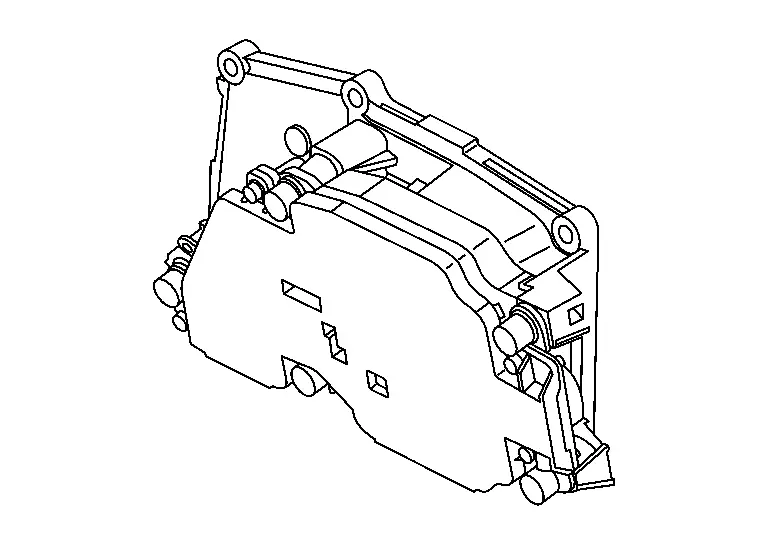
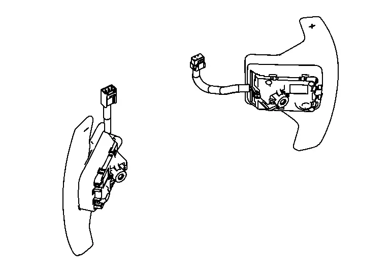
Electric Shift Control Module
FUNCTIONS WITHIN THE SYSTEM
The electric shift control module actuates the shift actuator according to the signals transmitted from electric shift sensor, P position switch and various ECUs.

INDIVIDUAL FUNCTION WITHIN THE SYSTEM
-
The electric shift control module consists of the microcomputer and input/output connectors for signal and power supply.
-
The electric shift control module includes a self-diagnosis function for simplifying trouble diagnosis.
INDIVIDUAL OPERATION
The electric shift control module is started by the ignition switch signal.
COMPONENT PARTS LOCATION
The electric shift control module is installed below the center console.
Electric Shift Selector
FUNCTIONS WITHIN THE SYSTEM
The electric shift selector sends the shift request of the driver to the electric shift control module as an electric signal.
INDIVIDUAL FUNCTION WITHIN THE SYSTEM
| Shift selector position | Operation/Function | |
|---|---|---|
|
H (Home position) |
The selector lever automatically moves back to the home position after it is operated. |
 : Shift without pressing the button : Shift without pressing the button |
|
P (P position switch) |
Completely stop the Nissan Ariya vehicle and press the P position switch while depressing the brake pedal. The shift position changes to P. | |
| R | While depressing the brake pedal, press the selector knob button and shift the selector lever to R position. The shift position changes to R. | |
| Nr |
When shift position is D or M, while depressing the brake pedal, shift the selector lever to the Nr position and hold it for approx. 0.5 second. The shift position changes to N.
Even if selector lever is shifted to the Nr position when shift position is R, the shift position does not change to N and the shift position warning buzzer sounds. |
|
| Nd |
When shift position is R, while depressing the brake pedal, shift the selector lever to the Nd position and hold it for approx. 0.5 second. The shift position changes to N.
Even if selector lever is shifted to the Nd position when shift position is D or M, the shift position does not change to N and the shift position warning buzzer sounds. |
|
| D/M |
|
|
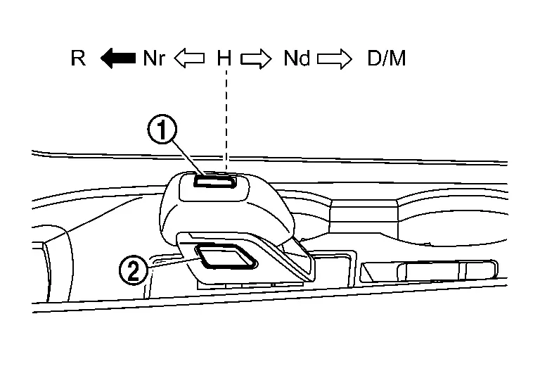
 : Press the button
  NOTE:
NOTE:
 : Hold
  : Current shift position
  : Be able to shift here
| POWER SW | Operation | Nissan Ariya Vehicle speed | Stop lamp switch | Shift position | Remarks | ||||
|---|---|---|---|---|---|---|---|---|---|
| P | R | N | D | M | |||||
| OFF/ACC | Selector lever | — | — | |
— | — | |||
| P position SW | — | — | |
— | — | ||||
|
ON (Engine stop) |
Selector lever | — | ON | |
— | |
— | — |
|
| — | OFF | |
— | Shift position warning buzzer: Two short beeps | |||||
| P position SW | — | — | |
— | |
— | — | — | |
|
ON (Engine running) |
Selector lever | — | ON | |
|
|
|
* |
— |
| — | OFF | |
— | Shift position warning buzzer: Two short beeps | |||||
| P position SW | 3 km/h (1.86 MPH) or less | — | |
|
|
|
|
— | |
| 3 km/h (1.86 MPH) or more | — | — | |
|
|
|
Shift position warning buzzer: Two short beeps | ||
*: Direct shifting to the M position from the P position is not possible.
INDIVIDUAL OPERATION
The electric shift selector sends a signal to the electric shift control module by shifting.
COMPONENT PARTS LOCATION
The electric shift selector is installed on the center console.
Electric Shift Sensor
FUNCTIONS WITHIN THE SYSTEM
The electric shift control module determines the shift selector position from the combination of the electric shift sensor ON/OFF signals.
INDIVIDUAL FUNCTION WITHIN THE SYSTEM
The electric shift sensor has 8 non-contact sensors (Hall IC) built in. Each sensor switches ON/OFF according to the selector lever position.
| Selector lever position | Electric shift sensor | |||||||
|---|---|---|---|---|---|---|---|---|
| No. 1 | No. 2 | No. 3 | No. 4 | No. 5 | No. 6 | No. 7 | No. 8 | |
| R | ON | ON | OFF | OFF | OFF | OFF | OFF | OFF |
| Nr | ON | ON | ON | ON | ON | OFF | OFF | OFF |
| H | ON | ON | ON | ON | ON | ON | ON | ON |
| Nd | OFF | OFF | OFF | ON | ON | ON | ON | ON |
| D/M | OFF | OFF | OFF | OFF | OFF | OFF | ON | ON |
INDIVIDUAL OPERATION
The electric shift sensor transmits ON/OFF signals according to the selector lever position to the electric shift control module.
COMPONENT PARTS LOCATION
The electric shift sensor is installed to the electric shift selector.

P Position Switch
FUNCTIONS WITHIN THE SYSTEM
The transaxle changes to P position by pressing the P position switch.
INDIVIDUAL FUNCTION WITHIN THE SYSTEM
The P position switch transmits the ON/OFF signals of 2 contact switches to the electric shift control module.
| P position switch | P position switch | |
|---|---|---|
| No. 1 | No. 2 | |
| Press | ON | OFF |
| No press | OFF | ON |
INDIVIDUAL OPERATION
The P position switch allows direct one-touch switching to the P position from any position while the Nissan Ariya vehicle is stopped.
COMPONENT PARTS LOCATION
The P position switch is installed on the electric shift selector.

Selector Indicator
FUNCTIONS WITHIN THE SYSTEM
The selector indicator indicates the currently selected shift position.
INDIVIDUAL FUNCTION WITHIN THE SYSTEM
The selector indicator informs to driver the currently selected shift position.
INDIVIDUAL OPERATION
The lamp of currently selected shift position turns ON.
COMPONENT PARTS LOCATION
The selector indicator is installed on selector knob.
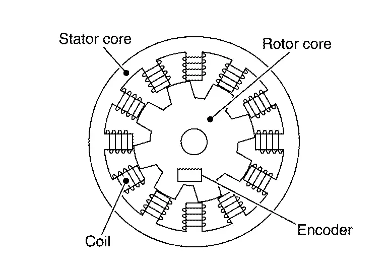
Shift Actuator
FUNCTIONS WITHIN THE SYSTEM
The shift actuator operates according to the output signal from the electric shift control module and changes the shift position of the transaxle.
INDIVIDUAL FUNCTION WITHIN THE SYSTEM
-
Motor
-
A 3-phase SR motor is used.
-
Coil is placed on the stator core around the motor and the current that passes through the coil in sequence generates the rotating force for the inner rotor core.
-
-
Encoder
-
The Hall IC type rotation angle sensor is used for higher accuracy in the detection of the rotor rotation angle.
-
It detects the rotor rotation angle and outputs pulse signals to the electric shift control module.
-
The electric shift control module controls the timing of the current feed to the coils optimally based on the signal from the encoder.
-
-
Actuator Reduction Gear
The actuator reduction gear consists of a cycloidal gear and includes a motor with its torque amplified for secure operation under high torque-requiring conditions.
INDIVIDUAL OPERATION
The shift actuator moves the manual shaft of transaxle and changes shift position.
COMPONENT PARTS LOCATION
The shift actuator is installed above the transaxle.
Shift Actuator Relay
FUNCTIONS WITHIN THE SYSTEM
The shift actuator relay supply power to the motor coil of shift actuator. Electric shift control module activates the shift actuator relay to supply power to the motor coil of shift actuator when the ignition switch is turned ON.
INDIVIDUAL FUNCTION WITHIN THE SYSTEM
The shift actuator relay connect and disconnects of the power supply circuit by ON / OFF of the relay switch.
INDIVIDUAL OPERATION
The relays used in the shift actuator relay are normal open relays.
COMPONENT PARTS LOCATION
The shift actuator relay is installed in front of the left front wheel.
Other materials:
Removal and Installation. Hood Lock
Exploded View
Hood lock
Hood lock release cable assembly
Hood lock release handle
: Clip
: N·m (kg-m, in-lb)
: Body grease
Hood Lock
Removal and Installation
REMOVALRemove front grill cover. Refer to Removal and Installation.
Disconnect hood lock switch har ...
Cvt: Ge0f14a. Symptom Diagnosis
Cvt Control System
Symptom Table
The diagnosis item number indicates the order of check. Start checking in the order from 1.
Perform diagnoses of symptom table 1 before symptom table 2.
Symptom Table 1 Diagnostic item Reference Symptom
Shift Shock Slips/Will Not Engage Other
...
Feux
Informations de base
Spot de lecture avant
Éclairage de miroir de courtoisie (si équipé)
Plafonnier (si équipé)
Clignotant latéral (si équipé)
Éclairage individuel arrière (si équipé)
Phare – feu de route
Phare – feu de croisement
Feu de stationnement avant / ...