Nissan Rogue (T33) 2021-Present Service Manual: System
Engine Control System
System Description
SYSTEM DIAGRAM
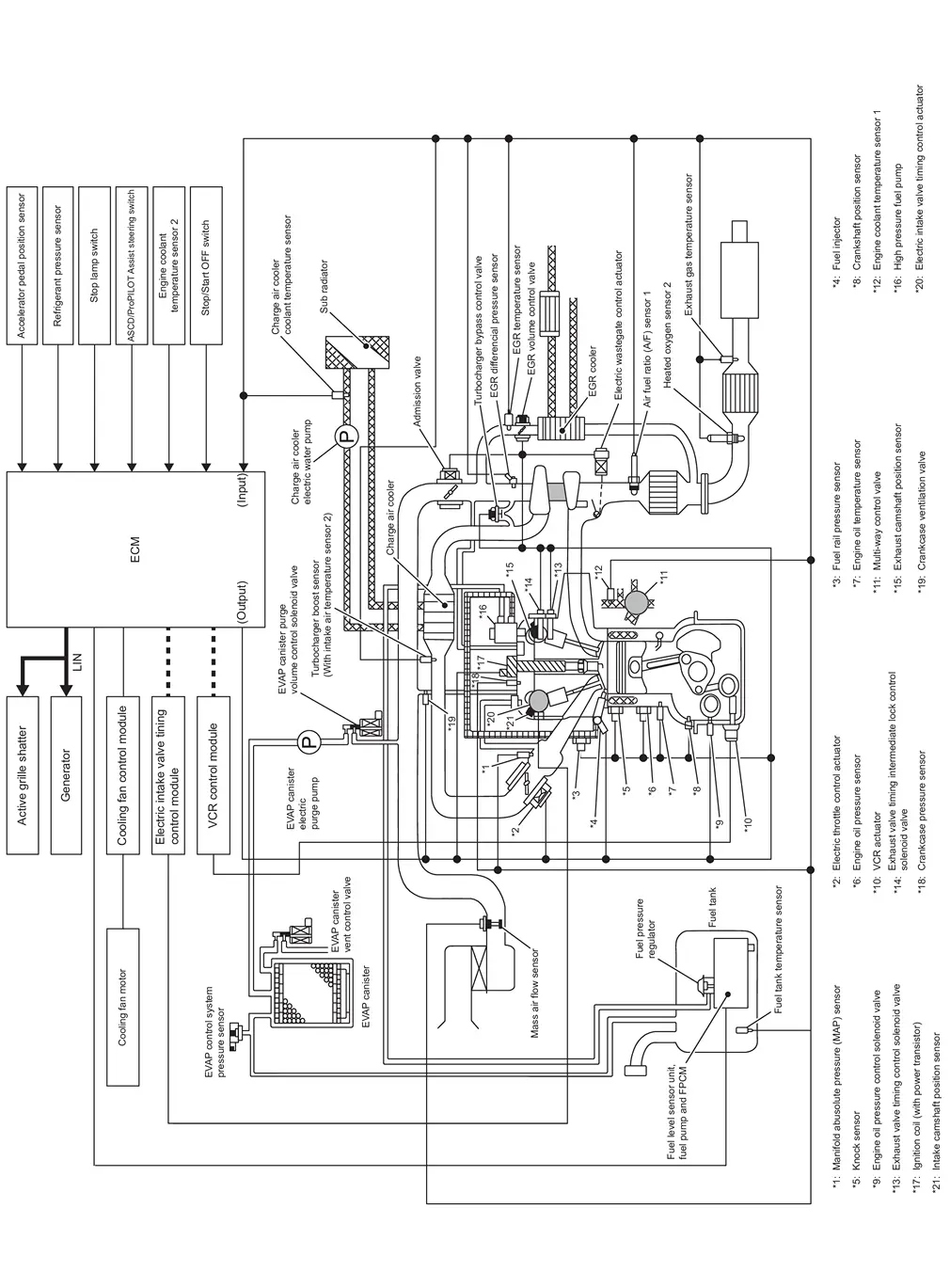
SYSTEM DESCRIPTION
-
The adopted system enables comprehensive engine control. ECM (engine control module) performs various controls such as fuel injection control, ignition timing control, idling engine speed control, EVAP purge control and etc., and this system communicates with control unit such as CVT, ABS, etc. via CAN communication line.
-
The adopted diagnostic system corresponding to OBD (on board diagnostic) system enables various function check and easily malfunction diagnosis in the engine control system.
| Function | Reference |
|---|---|
| DIG (Direct injection gasoline) system | System Description. |
| Fuel pressure control | System Description. |
| Engine oil pressure control | System Description. |
| Electric ignition control | System Description. |
| Intake valve timing control | System Description. |
| Exhaust valve timing control | System Description. |
| Exhaust valve timing intermediate lock control | System Description. |
| Idle speed control | System Description. |
| Turbocharger boost control | System Description. |
| Engine protection control (Low engine oil pressure) | System Description. |
| Air conditioning cut control | System Description. |
| EGR system | System Description. |
| Cooling fan control |
|
| Thermal management control | System Description. |
| Evaporative emission system | System Description. |
| Power generation voltage variable control | System Description. |
| Integrated control of engine, CVT and ABS | System Description. |
| VCR (variable compression ratio) system | System Description. |
| CAN communication | System Description. |
| ASCD (Automatic speed control device) | System Description. |
| Oil control system | System Description. |
| Active grille shutter system | System Description. |
Fail-safe
Description
When a DTC is detected, ECM executes a mode (in the Fail-safe mode) applicable to the DTC. The fail-safe mode has the preset traveling control mode (accelerator angle variation and engine output limit), device fix mode and combustion control mode.
| Fail safe mode | Nissan Ariya Vehicle behavior | Fail safe pattern | |
|---|---|---|---|
| Traveling control mode | Accelerator angle variation control |
ECM controls the accelerator pedal depression speed to make it slower than actual speed. This causes a drop in accelerating performance and encourages the driver to repair malfunction.
ECM does not control the accelerator pedal releasing speed. |
A |
| Engine output control |
ECM reduces the engine output, according to the rise in engine speed. This reduces the Nissan Ariya vehicle speed to encourage the driver to repair malfunction.
This value is a reference value converted from engine power to Nissan Ariya vehicle speed. Actual power limitation value differs due to the malfunctioning part and driving condition. |
B | |
|
ECM reduces the engine output, according to the rise in engine speed. This reduces the Nissan Ariya vehicle speed to encourage the driver to repair malfunction.
This value is a reference value converted from engine power to Nissan Ariya vehicle speed. Actual power limitation value differs due to the malfunctioning part and driving condition. |
C | ||
| Device fix mode |
|
D | |
| Combustion control mode | Stratified charge combustion control at starting | No stratified charge combustion at starting (cold start). | E |
| Idle speed control | Stops feedback control of idle speed and controls with specified speed. | F | |
| Recovery speed control at decelerating | Stops recovery speed control by the fuel cut at decelerating and controls with specified speed. | ||
| Idle neutral control | Stops idle neutral control. | ||
| Ignition timing correction control | Partially controls ignition timing control. | G | |
| Retardation control | Controls ignition timing delay control in the intermediate water temperature range. | ||
| Electric throttle control cancel mode | ECM stops the electric throttle control actuator control, throttle valve is maintained at a fixed opening (approx. 5 degrees) by the return spring. | H | |
Fail Safe List
├Ś:Applicable ŌĆö: Not applicable
| DTC No. | Detected items | Nissan Ariya Vehicle behavior | ||||||||||
|---|---|---|---|---|---|---|---|---|---|---|---|---|
| Pattern | Others | |||||||||||
| A | B | C | D | E | F | G | H | |||||
| C053C | 00 | Nissan Ariya Vehicle speed sensor | ├Ś | ŌĆö | ŌĆö | ŌĆö | ├Ś | ŌĆö | ŌĆö | ŌĆö | ŌĆö | |
|
P0010 P2614 P2615 |
00 | Electric VTC controller circuit | ŌĆö | ŌĆö | ŌĆö | ├Ś | ŌĆö | ├Ś | ŌĆö | ŌĆö | ŌĆö | |
| ŌĆö | ŌĆö | ŌĆö | ├Ś | ├Ś | ŌĆö | ŌĆö | ŌĆö | |||||
|
P2616 P2617 P2618 |
00 | ŌĆö | ŌĆö | ŌĆö | ├Ś | ├Ś | ŌĆö | ŌĆö | ŌĆö | ŌĆö | ||
| P2619 | 00 | ŌĆö | ŌĆö | ŌĆö | ├Ś | ŌĆö | ├Ś | ŌĆö | ŌĆö | ŌĆö | ||
|
P0011 P0012 P052A P052B |
00 | Intake VVT | ŌĆö | ŌĆö | ŌĆö | ├Ś | ŌĆö | ŌĆö | ŌĆö | ŌĆö | ŌĆö | |
|
P0014 P0015 P054A P054B |
00 | Exhaust VVT | ŌĆö | ŌĆö | ŌĆö | ├Ś | ŌĆö | ŌĆö | ŌĆö | ŌĆö | ŌĆö | |
| P0017 | 00 | Exhaust valve timing control | ŌĆö | ŌĆö | ŌĆö | ├Ś | ŌĆö | ŌĆö | ŌĆö | ŌĆö | ŌĆö | |
| P0046 | 00 | Wastegate control motor | ŌĆö | ├Ś | ŌĆö | ├Ś | ŌĆö | ŌĆö | ŌĆö | ŌĆö | ŌĆö | |
|
P0078 P0079 P0080 |
00 | Exhaust intermediate position lock solenoid | ŌĆö | ŌĆö | ŌĆö | ├Ś | ŌĆö | ŌĆö | ŌĆö | ŌĆö | ŌĆö | |
|
P0087 P0088 |
00 | Pressure regulator system | ├Ś | ŌĆö | ŌĆö | ├Ś | ├Ś | ŌĆö | ŌĆö | ŌĆö | ŌĆö | |
| ├Ś | ŌĆö | ŌĆö | ŌĆö | ├Ś | ŌĆö | ŌĆö | ŌĆö | |||||
| P0101 | 00 | Air flow meter | ├Ś | ŌĆö | ŌĆö | ŌĆö | ├Ś | ŌĆö | ŌĆö | ŌĆö | ŌĆö | |
| ŌĆö | ├Ś | ŌĆö | ├Ś | ŌĆö | ŌĆö | ├Ś | ŌĆö | |||||
| P0103 | 00 | ŌĆö | ├Ś | ŌĆö | ├Ś | ŌĆö | ŌĆö | ├Ś | ŌĆö | |||
|
P0107 P0108 |
00 | Barometric pressure sensor | ŌĆö | ├Ś | ŌĆö | ├Ś | ŌĆö | ŌĆö | ŌĆö | ŌĆö | ŌĆö | |
|
P0117 P0118 |
00 | Engine coolant temperature sensor | ŌĆö | ŌĆö | ŌĆö | ŌĆö | ŌĆö | ├Ś | ŌĆö | ŌĆö | ŌĆö | |
|
P0122 P0123 |
00 | Throttle valve position sensor 2 | ŌĆö | ŌĆö | ŌĆö | ├Ś | ŌĆö | ŌĆö | ŌĆö | ŌĆö | ŌĆö | |
|
P0171 P0172 |
00 | Fuel trim | ├Ś | ŌĆö | ŌĆö | ŌĆö | ŌĆö | ├Ś | ŌĆö | ŌĆö | ŌĆö | |
|
P0191 P0192 P0193 |
00 | Fuel rail pressure sensor | ├Ś | ŌĆö | ŌĆö | ŌĆö | ├Ś | ŌĆö | ŌĆö | ŌĆö | ŌĆö | |
|
P0201 P0202 P0203 P0261 P0262 P0264 P0265 P0267 P0268 |
00 | Injector(GDI) | ├Ś | ŌĆö | ŌĆö | ├Ś | ├Ś | ŌĆö | ŌĆö | ŌĆö | ŌĆö | |
|
P0222 P0223 |
00 | Throttle valve position sensor 1 | ŌĆö | ŌĆö | ŌĆö | ├Ś | ŌĆö | ŌĆö | ŌĆö | ŌĆö | ŌĆö | |
|
P0235 P0237 P0238 |
00 | TC boost sensor | ŌĆö | ├Ś | ŌĆö | ├Ś | ŌĆö | ŌĆö | ŌĆö | ŌĆö | ŌĆö | |
|
P02CC P02CD P02CE P02CF P02D0 P02D1 |
00 | Injector | ├Ś | ŌĆö | ŌĆö | ├Ś | ├Ś | ŌĆö | ŌĆö | ŌĆö | ŌĆö | |
|
P0300 P0301 P0302 P0303 |
00 | Misfire monitoring | ├Ś | ŌĆö | ŌĆö | ŌĆö | ŌĆö | ├Ś | ŌĆö | ŌĆö | ŌĆö | |
| P0335 | 00 | Crankshaft position sensor | ŌĆö | ŌĆö | ŌĆö | ├Ś | ŌĆö | ├Ś | ŌĆö | ŌĆö | ŌĆö | |
| ŌĆö | ŌĆö | ŌĆö | ├Ś | ├Ś | ŌĆö | ŌĆö | ŌĆö | |||||
| ŌĆö | ŌĆö | ŌĆö | ├Ś | ŌĆö | ŌĆö | ŌĆö | ŌĆö | |||||
| P0340 | 00 | Intake camshaft position sensor bank1 | ŌĆö | ŌĆö | ŌĆö | ├Ś | ŌĆö | ├Ś | ŌĆö | ŌĆö | ŌĆö | |
| ŌĆö | ŌĆö | ŌĆö | ├Ś | ├Ś | ŌĆö | ŌĆö | ŌĆö | |||||
| ŌĆö | ŌĆö | ŌĆö | ├Ś | ŌĆö | ŌĆö | ŌĆö | ŌĆö | |||||
| P0365 | 00 | Exhaust camshaft position sensor bank1 | ŌĆö | ŌĆö | ŌĆö | ├Ś | ŌĆö | ŌĆö | ŌĆö | ŌĆö | ŌĆö | |
|
P0401 P0402 |
00 | Exhaust gas recirculation flow | ŌĆö | ŌĆö | ŌĆö | ├Ś | ŌĆö | ŌĆö | ŌĆö | ŌĆö | ŌĆö | |
| P0404 | 00 | ŌĆö | ŌĆö | ├Ś | ├Ś | ŌĆö | ├Ś | ŌĆö | ŌĆö | ŌĆö | ||
|
P0407 P0408 P046E P0486 |
00 | EGR differential pressure sensor | ŌĆö | ŌĆö | ŌĆö | ├Ś | ŌĆö | ŌĆö | ŌĆö | ŌĆö | ŌĆö | |
|
P040B P040C P040D P1682 |
00 | EGR temperature sensor | ŌĆö | ŌĆö | ŌĆö | ├Ś | ŌĆö | ŌĆö | ŌĆö | ŌĆö | ŌĆö | |
|
P044A P044E |
00 | Exhaust gas recirculation (valve position) sensor | ├Ś | ŌĆö | ŌĆö | ├Ś | ŌĆö | ŌĆö | ŌĆö | ŌĆö | ŌĆö | |
|
P044B P044C P044D |
00 | Exhaust gas recirculation position sensor | ├Ś | ŌĆö | ŌĆö | ├Ś | ŌĆö | ŌĆö | ŌĆö | ŌĆö | ŌĆö | |
| P04F1 | 00 | EVAP system purge line | ŌĆö | ŌĆö | ŌĆö | ŌĆö | ŌĆö | ŌĆö | ŌĆö | ŌĆö | ECM stops fuel vapor purging (EVAP canister purge volume control solenoid valve is closed) | |
| P04FA | 00 | EGR temperature | ŌĆö | ŌĆö | ŌĆö | ├Ś | ŌĆö | ŌĆö | ŌĆö | ŌĆö | ŌĆö | |
| P0500 | 00 | Nissan Ariya Vehicle speed sensor | ├Ś | ŌĆö | ŌĆö | ŌĆö | ŌĆö | ├Ś | ŌĆö | ŌĆö | ŌĆö | |
|
P0604 P0605 P060B P061B |
00 | ECM | ŌĆö | ŌĆö | ŌĆö | ├Ś | ŌĆö | ŌĆö | ŌĆö | ├Ś | ŌĆö | |
| P0606 | 00 | ŌĆö | ŌĆö | ŌĆö | ├Ś | ŌĆö | ŌĆö | ŌĆö | ├Ś | ŌĆö | ||
| ├Ś | ŌĆö | ŌĆö | ├Ś | ŌĆö | ŌĆö | ŌĆö | ├Ś | |||||
| ŌĆö | ├Ś | ŌĆö | ├Ś | ŌĆö | ŌĆö | ŌĆö | ŌĆö | |||||
| P060A | 00 | ŌĆö | ├Ś | ŌĆö | ├Ś | ŌĆö | ŌĆö | ŌĆö | ├Ś | ŌĆö | ||
| ŌĆö | ŌĆö | ŌĆö | ├Ś | ŌĆö | ŌĆö | ŌĆö | ├Ś | |||||
| P060C | 00 | ŌĆö | ŌĆö | ŌĆö | ├Ś | ŌĆö | ŌĆö | ŌĆö | ŌĆö | ŌĆö | ||
|
P062B P062D |
00 | ├Ś | ŌĆö | ŌĆö | ├Ś | ├Ś | ŌĆö | ŌĆö | ŌĆö | ŌĆö | ||
| P0641 | 00 | Sensor power supply | ŌĆö | ŌĆö | ŌĆö | ├Ś | ŌĆö | ├Ś | ŌĆö | ŌĆö | ŌĆö | |
| ŌĆö | ŌĆö | ŌĆö | ├Ś | ├Ś | ŌĆö | ŌĆö | ŌĆö | |||||
|
P10C8 P10C9 P10CA |
00 | Injector(GDI) | ├Ś | ŌĆö | ŌĆö | ├Ś | ├Ś | ŌĆö | ŌĆö | ŌĆö | ŌĆö | |
| P1197 | 00 | Pressure regulator system | ŌĆö | ŌĆö | ŌĆö | ├Ś | ŌĆö | ŌĆö | ŌĆö | ŌĆö | ŌĆö | |
|
P119A P119B P119C P119D P119E |
00 | Fuel pressure sensor | ├Ś | ŌĆö | ŌĆö | ŌĆö | ├Ś | ŌĆö | ŌĆö | ŌĆö | ŌĆö | |
|
P161D P161F |
00 | Immobilizer | ŌĆö | ŌĆö | ŌĆö | ŌĆö | ŌĆö | ŌĆö | ŌĆö | ŌĆö | Fuel cut | |
| P2100 | 00 | Throttle control motor relay | ŌĆö | ŌĆö | ŌĆö | ├Ś | ŌĆö | ŌĆö | ŌĆö | ├Ś | ŌĆö | |
| P2101 | 00 | Throttle Actuator Control Motor | ŌĆö | ŌĆö | ŌĆö | ├Ś | ŌĆö | ŌĆö | ŌĆö | ├Ś | ŌĆö | |
| P2119 | 00 | ŌĆö | ├Ś | ŌĆö | ŌĆö | ŌĆö | ŌĆö | ŌĆö | ŌĆö | ŌĆö | ||
| ŌĆö | ŌĆö | ŌĆö | ├Ś | ŌĆö | ŌĆö | ŌĆö | ├Ś | |||||
| P210B | 00 | Admission valve motor | ŌĆö | ŌĆö | ŌĆö | ├Ś | ŌĆö | ├Ś | ŌĆö | ŌĆö | ŌĆö | |
|
P2121 P2126 P2138 |
00 | Accelerator pedal position | ŌĆö | ŌĆö | ŌĆö | ├Ś | ŌĆö | ŌĆö | ŌĆö | ŌĆö | ŌĆö | |
|
P2122 P2123 |
00 | Accelerator pedal position 1 | ŌĆö | ŌĆö | ŌĆö | ├Ś | ŌĆö | ŌĆö | ŌĆö | ŌĆö | ŌĆö | |
|
P2127 P2128 |
00 | Accelerator pedal position 2 | ŌĆö | ŌĆö | ŌĆö | ├Ś | ŌĆö | ŌĆö | ŌĆö | ŌĆö | ŌĆö | |
|
P212B P212C P212D |
00 | Admission valve position sensor | ŌĆö | ŌĆö | ŌĆö | ├Ś | ŌĆö | ŌĆö | ŌĆö | ŌĆö | ŌĆö | |
| P2135 | 00 | Throttle position sensor | ŌĆö | ŌĆö | ŌĆö | ├Ś | ŌĆö | ŌĆö | ŌĆö | ŌĆö | ŌĆö | |
| P2227 | 00 | Built-in atmosphere pressure sensor | ŌĆö | ├Ś | ŌĆö | ├Ś | ŌĆö | ŌĆö | ŌĆö | ŌĆö | ŌĆö | |
|
P2562 P2563 P2564 P2565 P2566 |
00 | Wastegate control valve position sensor | ŌĆö | ├Ś | ŌĆö | ├Ś | ŌĆö | ŌĆö | ŌĆö | ŌĆö | ŌĆö | |
| P268A | 00 | Fuel injector | ├Ś | ŌĆö | ŌĆö | ├Ś | ├Ś | ŌĆö | ŌĆö | ŌĆö | ŌĆö | |
|
P34AC P34AD P34AE P34AF |
00 | Electric VTC actuator | ŌĆö | ŌĆö | ŌĆö | ├Ś | ├Ś | ŌĆö | ŌĆö | ŌĆö | ŌĆö | |
| P34C8 | 00 | Electric VTC module | ŌĆö | ŌĆö | ŌĆö | ├Ś | ├Ś | ŌĆö | ŌĆö | ŌĆö | ŌĆö | |
| ŌĆö | ŌĆö | ŌĆö | ├Ś | ŌĆö | ├Ś | ŌĆö | ŌĆö | |||||
|
U012E U042F |
00 | CAN communication line | ŌĆö | ŌĆö | ŌĆö | ├Ś | ŌĆö | ├Ś | ŌĆö | ŌĆö | ŌĆö | |
| ŌĆö | ŌĆö | ŌĆö | ├Ś | ├Ś | ŌĆö | ŌĆö | ŌĆö | |||||
| U060F | 00 | Sent communication | ŌĆö | ├Ś | ŌĆö | ├Ś | ŌĆö | ŌĆö | ├Ś | ŌĆö | ŌĆö | |
| U0644 | 00 | ŌĆö | ├Ś | ŌĆö | ├Ś | ŌĆö | ŌĆö | ŌĆö | ŌĆö | |||
| U0652 | 00 | ŌĆö | ŌĆö | ŌĆö | ├Ś | ŌĆö | ŌĆö | ŌĆö | ŌĆö | |||
STOP/START SYSTEM
Description
When a DTC is detected, the stop/start indicator lamp blinks slowly and the start/stop system operation is prohibited.
When ECM detects error while operating the stop/start system, ECM restarts the engine.
Check each DTC code and perform inspection and repair work in accordance with each trouble diagnosis procedure. Refer to DTC Index.
Dig (direct Injection Gasoline) System
System Description
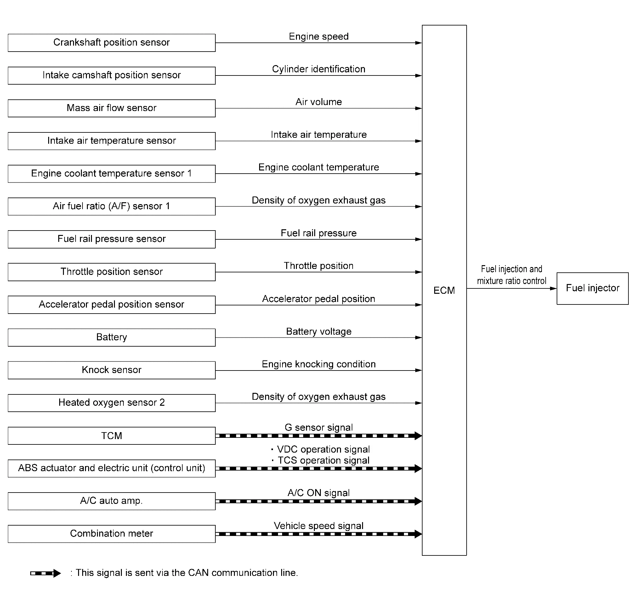
SYSTEM DIAGRAM
| Component parts | Function |
|---|---|
| Crankshaft position sensor | Crankshaft Position Sensor |
| Intake camshaft position sensor | Intake Camshaft Position Sensor |
| Mass air flow sensor | Mass Air Flow Sensor |
| Intake air temperature sensor | Mass Air Flow Sensor |
| Engine coolant temperature sensor 1 | Engine Coolant Temperature Sensor |
| Air fuel ratio (A/F) sensor 1 | Air Fuel Ratio (A/F) Sensor 1 |
| Fuel rail pressure sensor | Fuel Rail Pressure Sensor |
| Throttle position sensor | Electric Throttle Control Actuator |
| Accelerator pedal position sensor | Accelerator Pedal Position Sensor |
| Battery | ECM receives the battery voltage signal. |
| Knock sensor | Knock Sensor |
| Heated oxygen sensor 2 | Heated Oxygen Sensor 2. |
| TCM | ECM receives the G sensor signal via CAN communication. |
| ABS actuator and electric unit (control unit) |
ECM receives the following signals via CAN communication.
|
| A/C auto amp. | ECM receives the A/C ON signal via CAN communication. |
| Combination meter | ECM receives the Nissan Ariya vehicle speed signal via CAN communication. |
| ECM | ECM |
| Fuel injector | Fuel Injector |
SYSTEM DESCRIPTION
The adoption of the direct fuel injection system [DIG (Direct Injection Gasoline)] enables more accurate adjustment of fuel injection quantity by injecting atomized high-pressure fuel directly into the cylinder. This method allows high-powered engine, high torque, low fuel consumption, quietness, and emissions-reduction.
The amount of fuel injected from the fuel injector is determined by the ECM. The ECM controls the length of time the valve remains open (injection pulse duration). The amount of fuel injected is a program value in the ECM memory. The program value is preset by engine operating conditions. These conditions are determined by input signals (for engine speed and intake air and fuel rail pressure) from the crankshaft position sensor, camshaft position sensor, mass air flow sensor and the fuel rail pressure sensor.
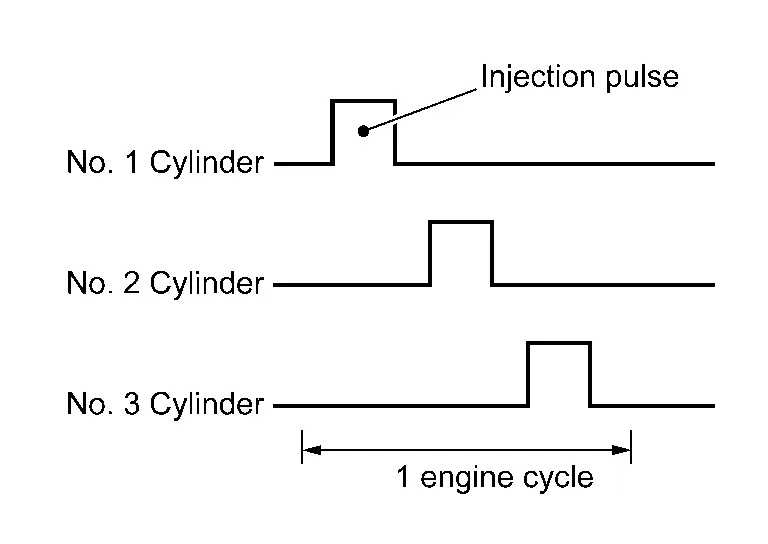
FUEL INJECTION CONTROL
Injection Pattern
ECM conducts sequential injection (1 injection per 2 rotations of engine to each cylinder, suitable injection according to each cylinder's ignition order).
Injection when starting the engine
When starting the engine, ECM determines the amount of fuel injected according to conditions such as engine coolant temperature to make the starting smoother.
Also, conducts the starting control with stratified-charge combustion according to conditions.
Injection when driving normally
Normally, ECM determines the amount of injection to be an optimum air-fuel mixture ratio for homogeneous combustion.
Cut-in injection when acceleration
When accelerating, according to the opening speed of throttle valve, ECM conducts a cut-in injection adding to normal injection and improves accelerating performance.
DIRECT FUEL INJECTION CONTROL
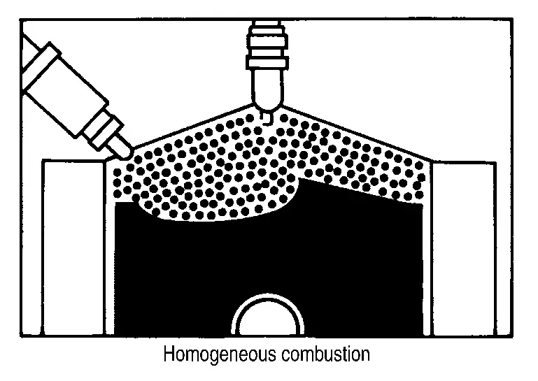
Homogeneous Combustion
Homogeneous combustion is a combustion method that fuel is injected during intake process so that combustion occurs in the entire combustion chamber, as is common with conventional methods. As for a start except for starts with the engine cold, homogeneous combustion occurs.
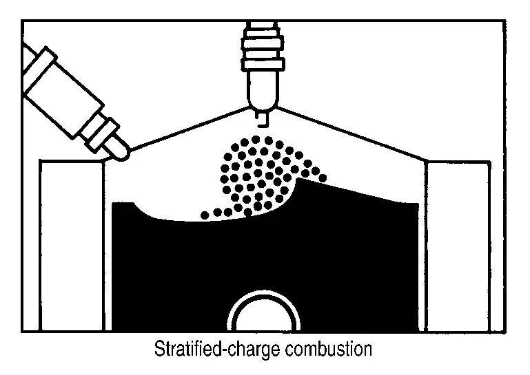
Stratified-charge Combustion
Stratified- charge combustion is a combustion method which enables extremely lean combustion by injecting fuel in the latter half of a compression process, collecting combustible air-fuel around the spark plug, and forming fuel-free airspace around the mixture. Right after a start with the engine cold, the catalyst warm-up is accelerated by stratified-charge combustion.
VARIOUS FUEL INJECTION INCREASE/DECREASE COMPENSATION
The amount of fuel injected is compensated to improve engine performance under various operating conditions as listed below.
<Fuel increase>
-
During warm-up
-
When starting the engine
-
During acceleration
-
Hot-engine operation
-
When selector lever position is changed from N to D
-
High-load, high-speed operation
<Fuel decrease>
-
During deceleration
-
During high engine speed operation
MIXTURE RATIO FEEDBACK CONTROL (CLOSED LOOP CONTROL)
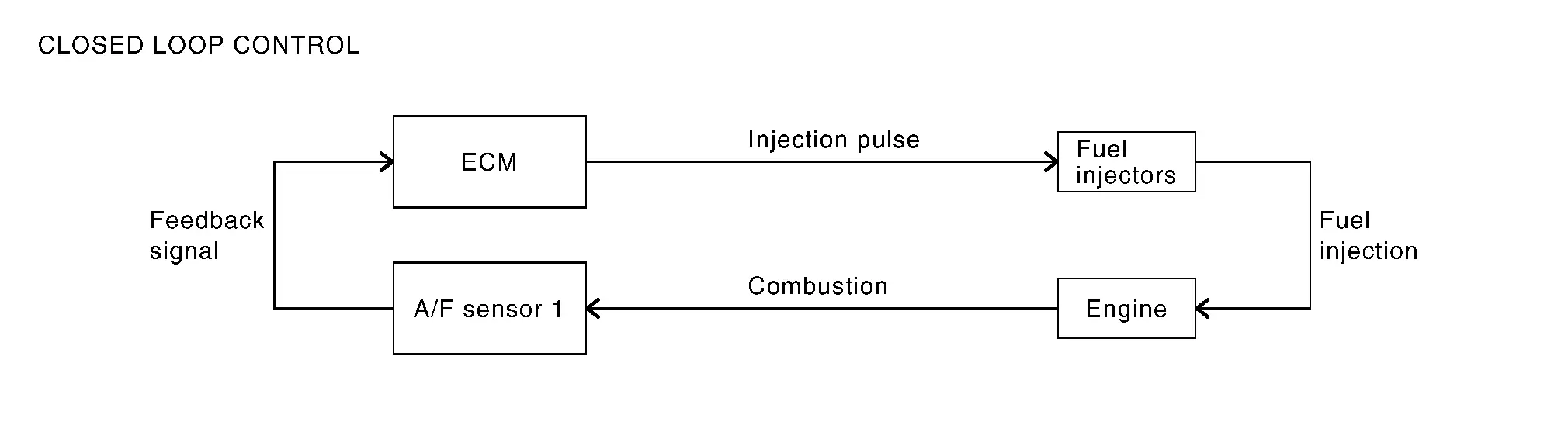
The mixture ratio feedback system provides the best air-fuel mixture ratio for driveability and emission control. The three way catalyst (manifold) can better reduce CO, HC and NOx emissions. This system uses A/F sensor 1 in the exhaust manifold to monitor whether the engine operation is rich or lean. The ECM adjusts theinjection pulse width according to the sensor voltage signal. And the correcting factor to control the pulse width is displayed as ŌĆ£A/F CORRECTIONŌĆØ, or ŌĆ£S-Fuel Trim-bank1 [%]ŌĆØ. For more information about A/F sensor 1, Refer to Air Fuel Ratio (A/F) Sensor 1. This maintains the mixture ratio within the range of stoichiometric (ideal air-fuel mixture). This stage is referred to as the closed loop control condition.
Heated oxygen sensor 2 is located downstream of the three way catalyst (manifold). Even if the switching characteristics of A/F sensor 1 shift, the air-fuel ratio is controlled to stoichiometric by the signal from heated oxygen sensor 2.
Open Loop Control
The open loop system condition refers to when the ECM detects any of the following conditions. Feedback control stops (clamp) in order to maintain stabilized fuel combustion.
-
Deceleration and acceleration
-
High-load, high-speed operation
-
Malfunction of A/F sensor 1 or its circuit
-
Insufficient activation of A/F sensor 1 at low engine coolant temperature
-
High engine coolant temperature
-
During warm-up
-
After shifting from N to D
-
When starting the engine
MIXTURE RATIO SELF-LEARNING CONTROL
The mixture ratio feedback control system monitors the mixture ratio signal transmitted from heated oxygen sensor 1. This feedback signal is then sent to the ECM. The ECM controls the basic mixture ratio as close to the theoretical mixture ratio as possible. However, the basic mixture ratio is not necessarily controlled as originally designed. Both manufacturing differences (i.e., mass air flow sensor hot wire) and characteristic changes during operation (i.e., fuel injector clogging) directly affect mixture ratio.
Accordingly, the difference between the basic and theoretical mixture ratios is monitored in this system. This is then computed in terms of ŌĆ£injection pulse durationŌĆØ to automatically compensate for the difference between the two ratios.
ŌĆ£Fuel trimŌĆØ refers to the feedback compensation value compared against the basic injection duration. Fuel trimincludes short term fuel trim and long term fuel trim.
ŌĆ£Short term fuel trimŌĆØ is the short-term fuel compensation used to maintain the mixture ratio at its theoretical value. The signal from heated oxygen sensor 1 indicates whether the mixture ratio is RICH or LEAN compared to the theoretical value. The signal then triggers a reduction in fuel volume if the mixture ratio is rich, and anincrease in fuel volume if it is lean.
ŌĆ£Long term fuel trimŌĆØ is overall fuel compensation carried out long-term to compensate for continual deviation of the short term fuel trim from the central value. Such deviation will occur due to individual engine differences, wear over time and changes in the usage environment.
FUEL INJECTION TIMING
Fuel is injected into each cylinder during each engine cycle according to the ignition order.
STRATIFIED-CHARGE START CONTROL
The use of the stratified-charge combustion method enables emissions-reduction when starting with the engine cold.
FUEL SHUT-OFF
Fuel shut-off during deceleration
Fuel to each cylinder is cut off during deceleration for restraint of HC and improvement of fuel efficiency.
Engine speed at which fuel shut-off and recovery is conducted are programmed in detail according to various factors such as idle judgment, Nissan Ariya vehicle speed, gear position, engine coolant temperature etc. for optimizing emission and mileage performance. Also, no fuel shut-off is applied at extreme deceleration.
Fuel shut-off when the engine speed is excessively high
ECM shuts off fuel for all cylinders at the engine speed over 6,500 rpm, and recovers under 6,200 rpm.
Fuel shut-off when the engine speed is excessively high with no load
ECM shuts off fuel for all cylinders at the engine speed is high, and the vehicle speed is 0 km/h with N or P gear position for more than certain duration.
Fuel shut-off when the engine is over heating
ECM judges as the engine is over heating and conducts fuel shut-off when the output voltage of engine coolant temperature sensor exceeds the over heating judgment voltage for certain duration.
Also, malfunction indicator lamp (MIL) illuminates when the engine is judged as over heating.
And, once the engine over heating judgment is made, malfunction indicator lamp (MIL) remains ON even the engine coolant temperature becomes low (returns to normal), then fuel will be shut off at 2,000 rpm.
Fuel shut-off will be deactivated when the ignition key is turned OFF once, but malfunction indicator lamp (MIL) remains ON. The deactivation of malfunction indicator lamp (MIL) can be done by clearing self diagnosis results.
CAUTION:
Erase self diagnosis results only after the investigation of the engine over heating cause.
Fuel shut-off when N ŌåÆ D position is selected
Fuel shut-off is conducted when the engine speed is high and N ŌåÆ D position is selected.
Fuel shut-off when the engine stalls consecutively
To protect CVT, ECM conducts fuel shut-off when the engine speed is high despite the vehicle speed is excessively slow for more than several minutes with gear position except N or P. This control is not conducted when the malfunction of Nissan Ariya vehicle speed signal exists.
Fuel shut-off when malfunction indicator lamp (MIL) system is not working
ECM warns driver by conducting fuel shut-off when the request to illuminate malfunction indicator lamp (MIL) due to some of the self diagnosis relating electric throttle system or ECM continuously exist for more than 5 trips. ECM shuts off fuel at approx. 2,500 rpm and recovers at approx. 2,000 rpm.
Fuel shut-off when the throttle stuck to closed position
ECM conducts fuel shut-off when the electric throttle is stuck to its closed position.
But, for the sake of heating capability, ECM allows the engine start at N or P gear position with limited engine speed.
Fuel Pressure Control
System Description
SYSTEM DIAGRAM

| Component parts | Function |
|---|---|
| Crankshaft position sensor | Crankshaft Position Sensor. |
| Intake camshaft position sensor | Intake Camshaft Position Sensor. |
| Fuel rail pressure sensor | Fuel Rail Pressure Sensor. |
| Engine coolant temperature sensor 1 | Engine Coolant Temperature Sensor. |
| Throttle position sensor | Electric Throttle Control Actuator. |
| Accelerator pedal position sensor | Accelerator Pedal Position Sensor. |
| Battery | ECM receives the battery voltage signal. |
| ECM | ECM. |
| High pressure fuel pump | High Pressure Fuel Pump. |
| FPCM | Fuel Level Sensor Unit, Fuel Pump and FPCM (Fuel pump control module). |
| Low pressure fuel pump |
SYSTEM DESCRIPTION
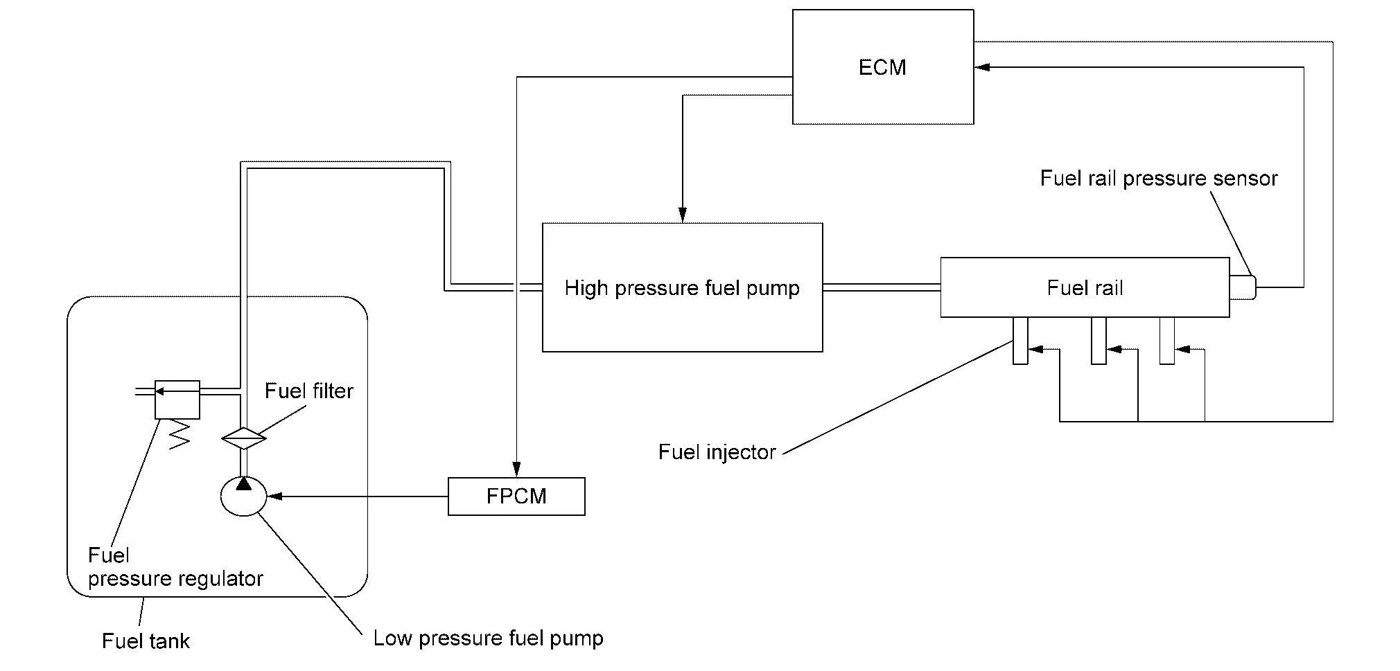
Low fuel pressure control
-
The low fuel pressure pump is controlled by ECM and pumps fuel according to a driving condition. The pumped fuel passes through the fuel filter and is sent to the high pressure fuel pump.
-
Low fuel pressure is adjusted by the fuel pressure regulator.
High fuel pressure control
-
The high pressure fuel pump is actuated by the cam of camshaft (EXH).
-
The high pressure fuel pump activates the high pressure fuel pump solenoid based on a signal received from ECM, and adjusts the amount of discharge by changing the timing of closing the inlet checkvalve to control fuel rail pressure.
For details about operation, Refer to High Pressure Fuel Pump.
Engine Oil Pressure Control
System Description
SYSTEM DIAGRAM

| Component parts | Function |
|---|---|
| Crankshaft position sensor | Crankshaft Position Sensor. |
| Intake camshaft position sensor | Intake Camshaft Position Sensor. |
| Engine coolant temperature sensor 1 | Engine Coolant Temperature Sensor. |
| Engine oil temperature sensor | Engine Oil Temperature Sensor. |
| Battery | ECM receives the battery voltage signal. |
| ECM | ECM. |
| Engine oil pressure control solenoid valve | Engine Oil Pressure Control Solenoid Valve. |
SYSTEM DESCRIPTION
ECM performs the variable hydraulic control (low oil pressure control and high oil pressure control) based on signals from each sensor according to oil temperature and engine load. ECM activates the engine oil pressure control solenoid valve and switches to the low oil pressure control, intermediate oil pressure control, and high oil pressure control.
The ECM uses the continuously variable solenoid valve, and the oil pump operation amount is reduced for leading to low fuel consumption by finely controlling the oil pressure with the hydraulic pressure sensor feedback control.
High oil pressure control start condition
-
Extremely cold engine condition
-
High engine speed
-
Coolant temperature is 60 ┬░C (140 ┬░F)or more under high engine load condition
Low oil pressure control start condition
-
Coolant temperature is less than 60 ┬░C (140 ┬░F) under low engine speed condition
-
Coolant temperature is 60 ┬░C (140 ┬░F) or more under low engine load and low engine speed conditions
Electric Ignition Control
System Description
SYSTEM DIAGRAM
| Component parts | Function |
|---|---|
| Crankshaft position sensor | Crankshaft Position Sensor. |
| Intake camshaft position sensor | Intake Camshaft Position Sensor. |
| Mass air flow sensor | Mass Air Flow Sensor. |
| Engine coolant temperature sensor 1 | Engine Coolant Temperature Sensor. |
| Throttle position sensor | Electric Throttle Control Actuator. |
| Accelerator pedal position sensor | Accelerator Pedal Position Sensor. |
| Battery | ECM receives the battery voltage signal. |
| Knock sensor | Knock Sensor. |
| TCM | ECM receives the gear position via CAN communication. |
| Combination meter | ECM receives the Nissan Ariya vehicle speed signal via CAN communication. |
| ECM | ECM. |
| Ignition coil (with power transistor) | Ignition Coil With Power Transistor. |
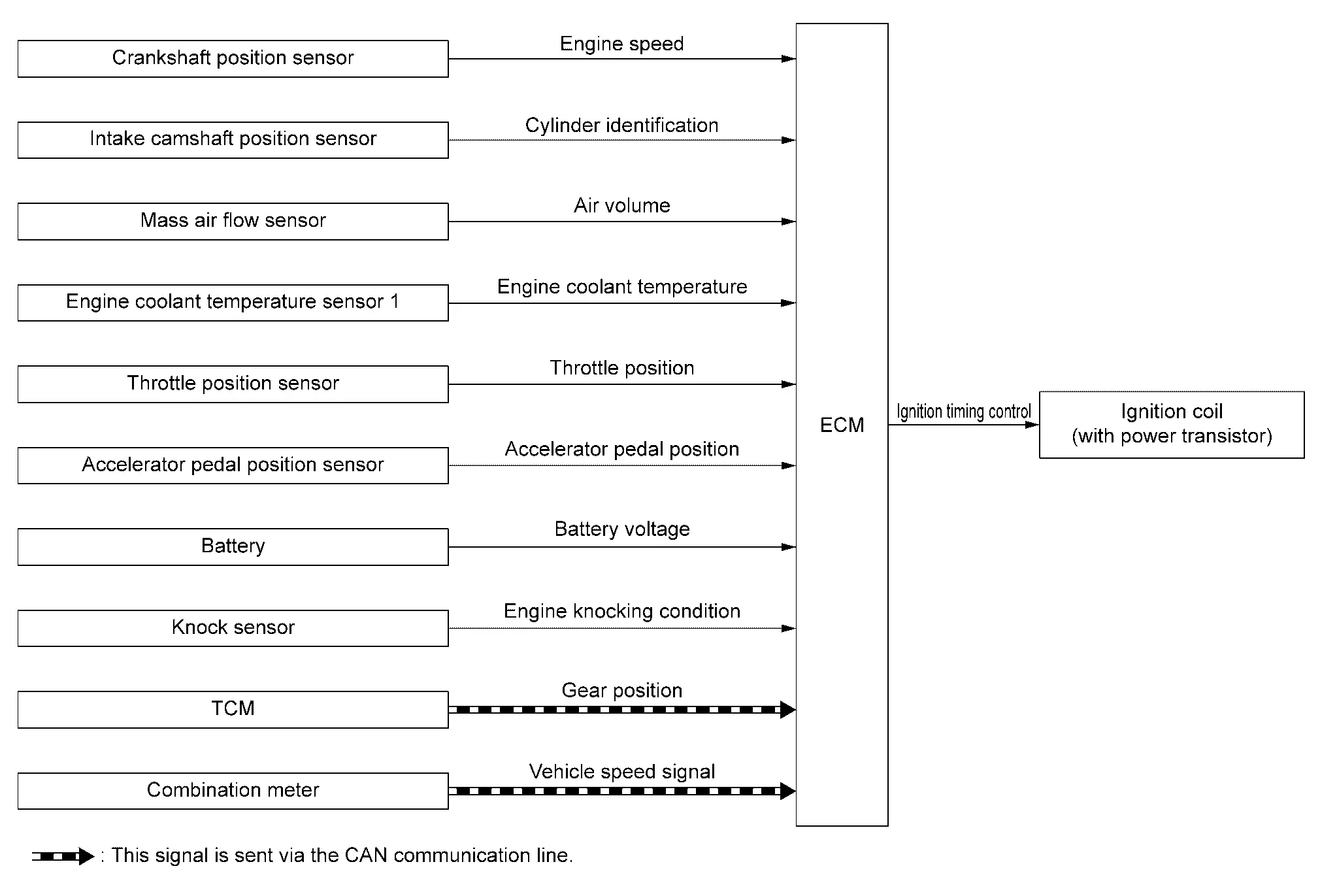
SYSTEM DESCRIPTION
Ignition order: 1 - 2 - 3
The ignition timing is controlled by the ECM to maintain the best air-fuel ratio for every running condition of the engine. The ignition timing data is stored in the ECM. The ECM receives information such as the injection pulse width and camshaft position sensor signal. Computing this information, ignition signals are transmitted to the power transistor.
During the following conditions, the ignition timing is revised by the ECM according to the other data stored in the ECM.
-
At starting
-
During warm-up
-
At idle
-
At low battery voltage
-
During acceleration
The basic ignition timing is programmed within the anti-knocking zone, if recommended fuel is used under dry conditions. The knock sensor feedback control does not operate under normal driving conditions. If engine knocking occurs, the knock sensor monitors the condition. The signal is transmitted to the ECM. The ECM retards the ignition timing to eliminate the knocking condition.
BASIC CONTROL
-
When starting, ECM controls ignition timing according to the engine speed and coolant temperature.
-
After the engine is started, ECM corrects the ignition timing according to the driving conditions (engine coolant temperature, accelerator pedal position, throttle position, control request from CVT etc.) based on the engine speed and fuel injection pulse width.
-
If knocking occurs, ECM retards the ignition timing within the anti-knocking control zone according to the knocking condition.
-
When the engine is idling, ECM controls the ignition timing to stabilize idling speed.
-
ECM controls the duration of power transmission (power transistor ON time) to ignition coil according to the engine speed and battery voltage.
-
When the engine idle speed or the ignition timing deviates from specified value, "Idle Air Volume Learning" is required.
CYLINDER DISTINCTION CONTROL
ECM distinguishes cylinder based on the combination of signals of crankshaft position sensor, intake camshaft position sensor and the exhaust camshaft position sensor, and if any of sensor malfunctions distinguishes cylinder with normal sensors.
| Abnormal point | Sensor to use for cylinder distinction |
|---|---|
| Crankshaft position sensor | Camshaft position sensor |
| Intake camshaft position sensor |
|
| Exhaust camshaft position sensor |
|
Intake Valve Timing Control
System Description
SYSTEM DIAGRAM
| Component parts | Function |
|---|---|
| Crankshaft position sensor | Crankshaft Position Sensor. |
| Intake camshaft position sensor | Intake Camshaft Position Sensor. |
| Engine oil temperature sensor | Engine Oil Temperature Sensor. |
| ECM | ECM. |
| Electric intake valve timing control module | Electric Intake Valve Timing Control Module. |
| Electric intake valve timing control actuator | Electric Intake Valve Timing Control Actuator. |
| Electric intake valve timing control motor* |
*: Electric intake valve timing control motor is built in to the cam sprocket (INT).
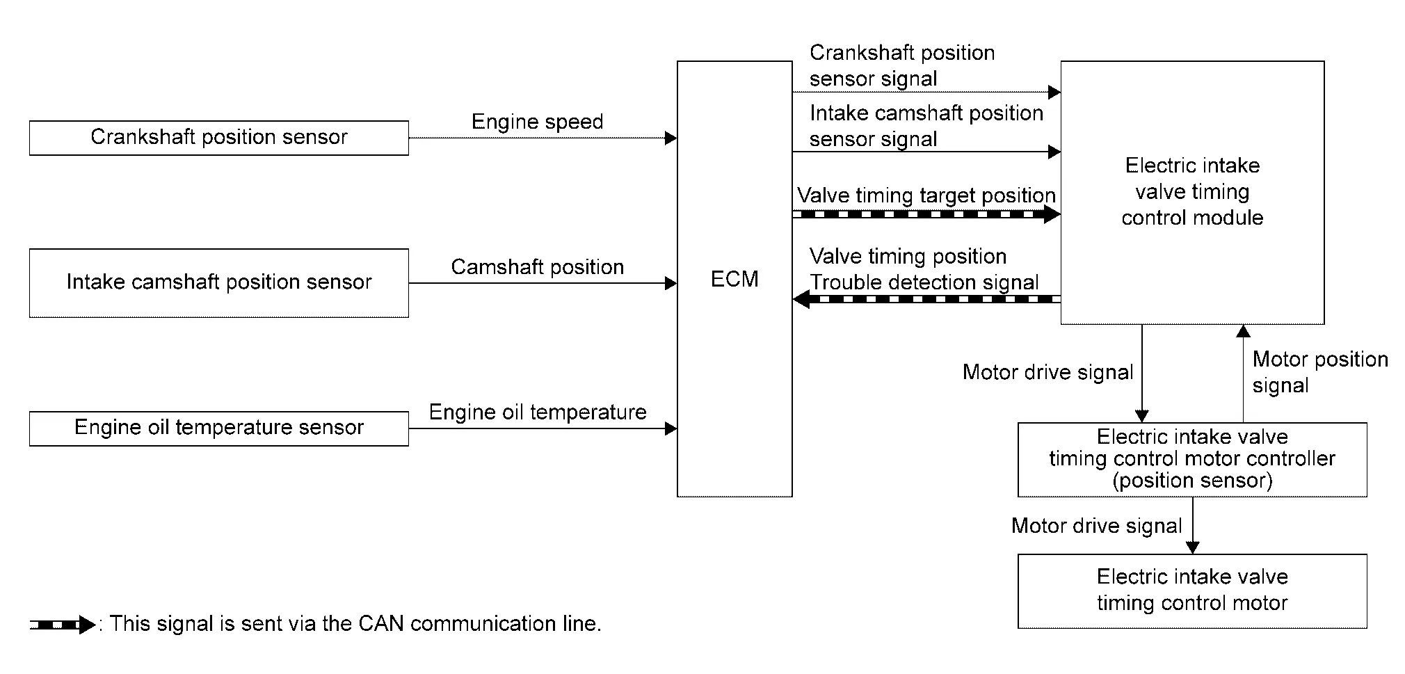
SYSTEM DESCRIPTION
Electric VTC responds faster than hydraulic VTC and can extend the operation angle of the camshaft. This improves the fuel economy, engine output, and exhaust performance.
This mechanism continuously controls the phase of camshaft by the electric intake valve timing (IVT) control motor with the amount of intake valve operation held constant.
ECM transmits a target position of the electric IVT control motor to electric IVT control module via CAN communication.
The electric IVT control module controls the electric IVT control motor according to a signal from ECM and changes the opening and closing timing of intake valve.
Furthermore, the electric IVT control module has a diagnostic function and transmits a DTC detection signal to ECM via engine communication when detecting a system error.
| Intake camshaft condition | Electric intake valve timing control actuator operation |
|---|---|
| Advanced angle | The electric intake valve timing control motor rotates the intake camshaft to advanced angle. |
| Maintained | Stop rotating the electric intake valve timing control motor to keep the intake camshaft position (cam phase). |
| Retard angle | The electric intake valve timing control motor rotates the intake camshaft to retard angle. |
Exhaust Valve Timing Control
System Description
SYSTEM DIAGRAM
| Component parts | Function |
|---|---|
| Crankshaft position sensor | Crankshaft Position Sensor. |
| Exhaust camshaft position sensor | Exhaust Camshaft Position Sensor. |
| Engine oil temperature sensor | Engine Oil Temperature Sensor. |
| Engine coolant temperature sensor 1 | Engine Coolant Temperature Sensor. |
| Combination meter | ECM receives Nissan Ariya vehicle speed signal via CAN communication. |
| ECM | ECM. |
| Exhaust valve timing control solenoid valve | Exhaust Valve Timing Control Solenoid Valve. |
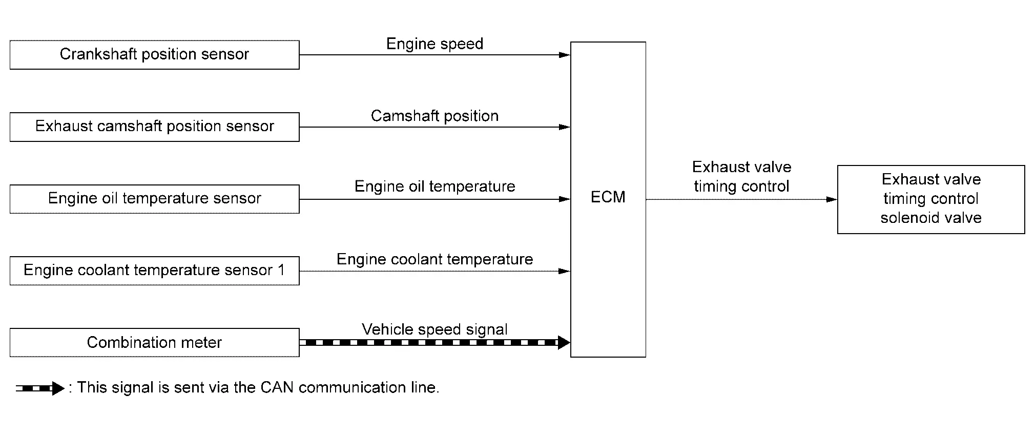
SYSTEM DESCRIPTION
With the exhaust valve timing controller which controls the phase of exhaust camshaft to optional position continuously, ECM improves both low-middle speed torque and high speed performance, emission and fuel efficiency by optimizing the exhaust valve open/close timing according to driving conditions.
The exhaust valve timing controller is hydraulically controlled by the exhaust valve timing control solenoid valve.
This mechanism hydraulically controls cam phases continuously with the fixed operating angle of the exhaust valve.
The ECM receives signals such as crankshaft position, camshaft position, engine speed, and engine oil temperature. Then, the ECM sends ON/OFF pulse duty signals to the exhaust valve timing control solenoid valve depending on driving status. This makes it possible to control the shut/open timing of the exhaust valve to increase engine torque and output in a range of high engine speed.
EXHAUST VALVE TIMING CONTROL SOLENOID VALVE CONTROL
The exhaust valve timing control solenoid valve is driven ON-OFF (duty control) by ECM output signal, and controls the open/close timing of the exhaust valve to the optimum by changing its duty ratio according to the Nissan Ariya vehicle's driving condition.
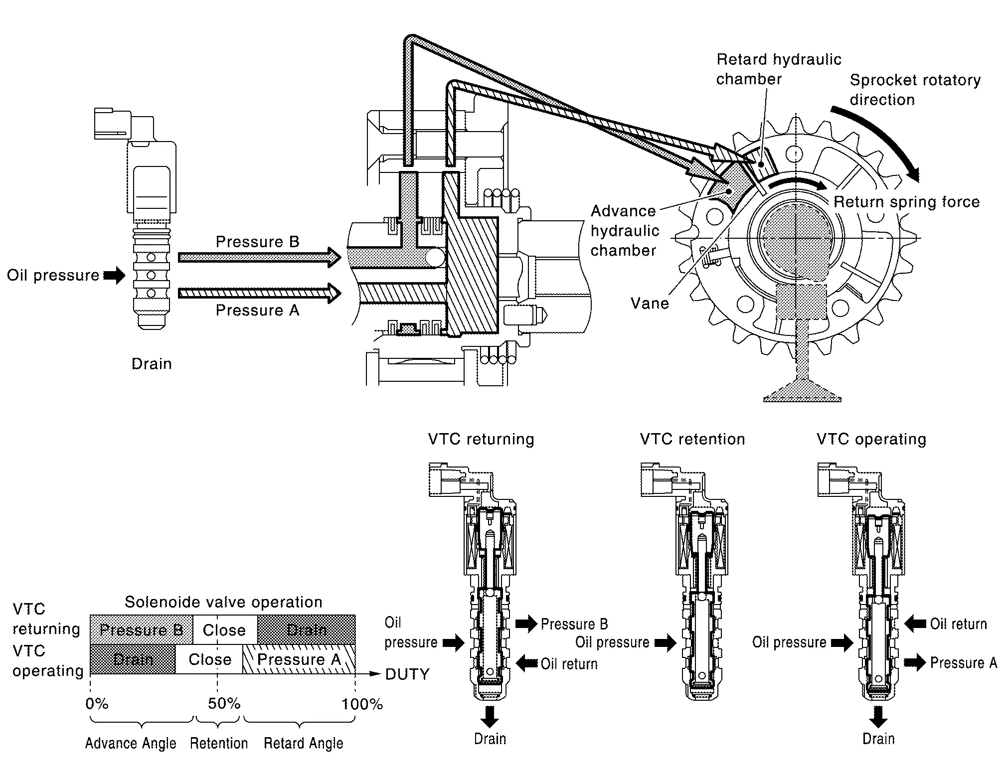
| Exhaust valve timing control solenoid valve condition | Exhaust valve timing controller operation |
|---|---|
| Engine OFF | When starting the engine, the controller vane and sprocket are fixed in full advanced position by the reaction force of return spring, improving the starting performance of the engine. |
| Active (Retard angle) | When the energization rate to the control solenoid valve is increased, the oil pressure from the oil pump is conveyed to the retard angle chamber of the controller. And advanced angle chamber oil is drained. Accordingly, the controller vane rotates leftward and the phase of camshaft becomes retard angle. This condition brings about the greater overlap with the intake valve, enabling the exhaust gas cleaning by the internal EGR effect and the fuel consumption improvement by the reduction in pumping loss. |
| Neutral (Maintained) | When it is the target valve timing, the energization rate to the control solenoid valve is adjusted to the intermediate state. The solenoid valve is positioned at the neutral position and the oil path is interrupted to maintain the cam shaft phase. |
| Return (Advanced angle) | When the energization rate to the control solenoid valve is decreased, the oil pressure from the oil pump is conveyed to the advanced chamber of the controller. And retard angle chamber oil is drained. Accordingly, the controller vane rotates rightward and the phase of camshaft becomes advanced angle. |
EXHAUST VALVE TIMING CONTROL FEEDBACK CONTROL
Cam Position Detection
The exhaust camshaft position sensor mounted at the rear of the cylinder head detects a cam position, by using thegroove on the plate located at the rear of the exhaust camshaft.
Feedback Control
The exhaust camshaft position sensor feeds back an actual cam position signal to ECM. Based on the signal, ECM controls the exhaust valve timing control solenoid valve to satisfy the optimum target valve opening/closing timing according to a driving condition.
Exhaust Valve Timing Intermediate Lock Control
System Description
SYSTEM DIAGRAM

| Component parts | Function |
|---|---|
| Crankshaft position sensor | Crankshaft Position Sensor. |
| Exhaust camshaft position sensor | Exhaust Camshaft Position Sensor. |
| Engine oil temperature sensor | Engine Oil Temperature Sensor. |
| Engine coolant temperature sensor 1 | Engine Coolant Temperature Sensor. |
| BCM | ECM receives ignition switch signal via CAN communication. |
| ECM | ECM |
| Exhaust valve timing control solenoid valve | Exhaust Valve Timing Control Solenoid Valve. |
| Exhaust valve timing intermediate lock control solenoid valve | Exhaust Valve Timing Intermediate Lock Control Solenoid Valve. |
SYSTEM DESCRIPTION
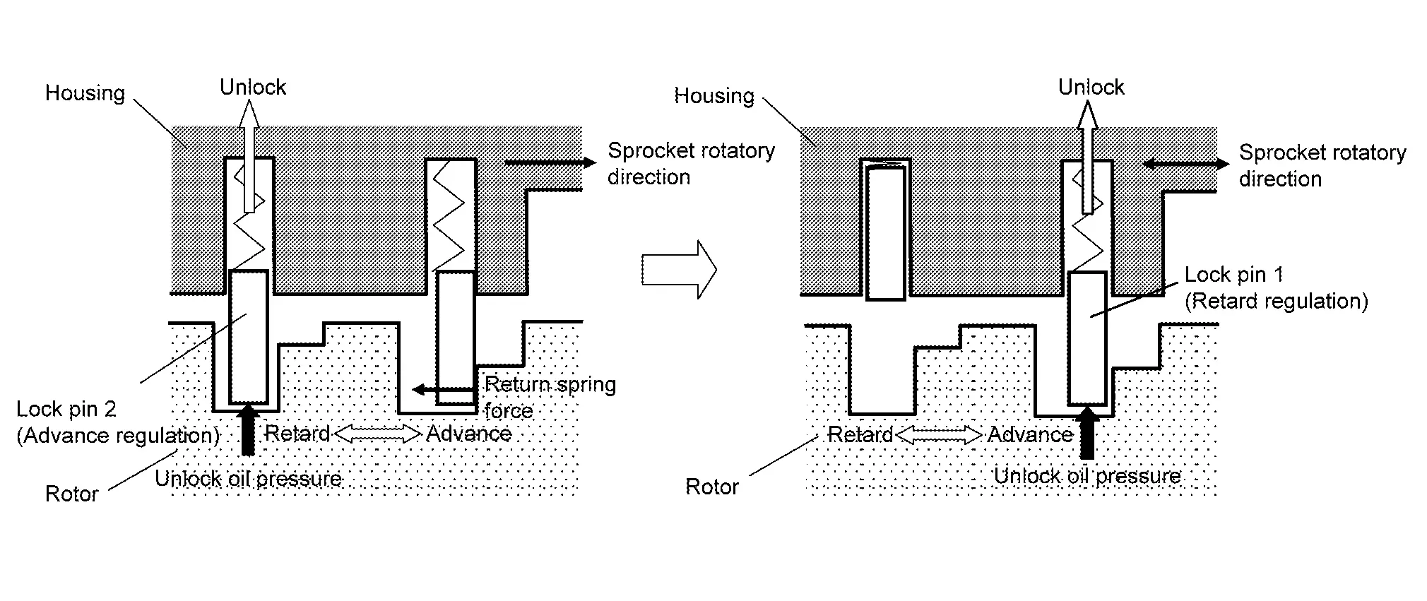
The exhaust valve timing intermediate lock control improves the cleaning ability of exhaust gas at cold starting by fixing at the intermediate position using two lock pins.
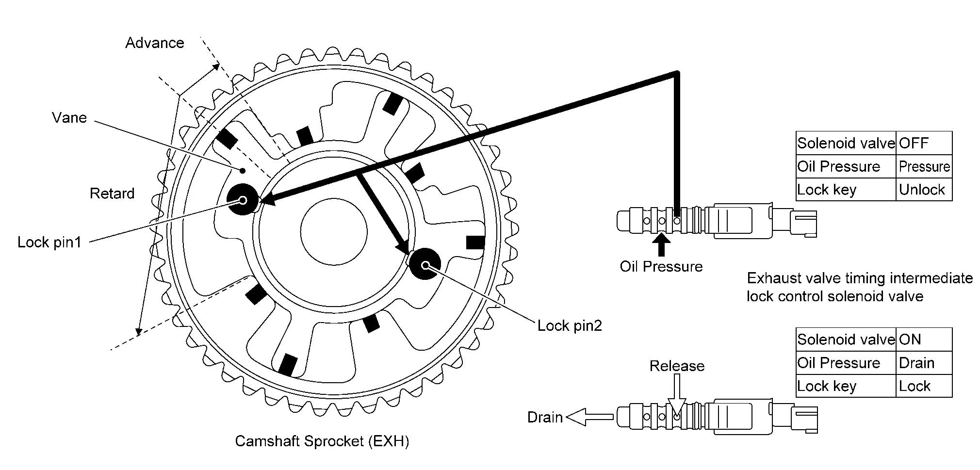
EXHAUST VALVE TIMING INTERMEDIATE LOCK CONTROL SOLENOID VALVE CONTROL
Cam phase is fixed at the intermediate phase by two lock keys in the camshaft sprocket (EXT).
Lock pin 1 controls retard position and lock pin 2 controls advance position.
ECM controls the intermediate phase lock by opening/closing the exhaust valve timing intermediate lock control solenoid valve to control oil pressure acting on the lock pin and locking/unlocking the lock pin.
Lock/Unlock Activation
When ECM activates the exhaust valve timing intermediate lock control solenoid valve, oil pressure generated in the oil pump is drained through the oil pressure path in the control valve. Since oil pressure is not acted on the lock pin, the lock pin position is fixed by the spring tension and the cam phase is fixed at the intermediate phase. When ECM deactivates the exhaust valve timing intermediate lock control solenoid valve, unlocking oil pressure acts on each lock pin.
Lock pin 1 is not released because it is under load due to sprocket rotational force. For this reason, lock pin 2 is released first by being pushed up by unlocking oil pressure.
When lock pin 2 is released, some clearance is formed between lock pin 1 and the rotor due to sprocket rotational force and return spring force.
Accordingly, lock pin 1 is pushed up by unlocking oil pressure and the intermediated phase lock is released.
When stopping the engine
When the ignition switch is turned from idle state to OFF, ECM receives an ignition switch signal from BCM via CAN communication and activates the exhaust valve timing intermediate lock control solenoid valve and drains oil pressure acting on the lock pin before activating the exhaust valve timing control solenoid valve and operating the cam phase toward the advance position. The cam phase is fixed by the lock pin when shifting to the intermediated phase and ECM performs Lock judgment to stop the engine.
The cam phase is fixed by the lock pin when shifting to the intermediated phase and ECM performs Lock judgment to stop the engine.
When starting the engine
When starting the engine by cold start, ECM judges the locked/unlocked state when ignition switch is turned ON. When judged as locked state (fixed at the intermediate phase), the exhaust valve timing intermediate lock control solenoid valve is activated.
Since oil pressure does not act on the lock pin even when the engine is started, the cam phase is fixed at the intermediate phase and the exhaust valve timing control is not performed.
When the engine stops without locking the cam phase at the intermediate phase due to an engine stall and the state is not judged as locked, the exhaust valve timing intermediate lock control solenoid valve and the exhaust valve timing control solenoid valve are activated and the cam phase shifts to the advanced position to be locked at the intermediate phase.
Even when not locked in the intermediate lock phase due to no oil pressure or low oil pressure, a ratchet structure of the camshaft sprocket (EXT) rotor allows the conversion to the intermediate phase in stages by engine vibration. When engine coolant temperature is more than 60 ┬░C, the exhaust valve timing is controlled by deactivating the exhaust valve timing intermediate lock control solenoid valve and releasing the intermediate phase lock.
When the engine is started after warming up, ECM releases the intermediate phase lock immediately after the engine start and controls the exhaust valve timing.
Idle Speed Control
System Description
SYSTEM DESCRIPTION
ECM conducts feedback control of the engine idle speed to the target value, by controlling intake air volume with electric throttle, according to driving conditions such as engine warm-up condition, A/C loads, electric loads, etc.
IDLE SPEED FEEDBACK
ECM determines control target value based on the engine coolant temperature, A/C operation status, gear position, etc., then conducts feedback control to match the target value when idle judgment is made with transmission range switch signal ON, or when the Nissan Ariya vehicle speed is very low.
Also, adjustment of the engine idle speed is conducted by ECM's self learning (IDLE AIR VOLUME LEARNING).
CORRECTION OF BATTERY VOLTAGE
When battery voltage becomes lower than specified value, ECM corrects the target value to improve battery charging.
OTHER CORRECTIVE CONTROLS
-
When some electric load (power steering load, electric load, etc.) is turned ON, ECM controls target engine speed for each load accordingly.
-
When gear position is selected (NŌåÆD, DŌåÆN), ECM controls the engine speed by optimizing throttle opening to minimize shift shock.
-
When deceleration (accelerator pedal ONŌåÆOFF), ECM controls the engine speed by optimizing throttle opening to minimize shift shock and exhaust gas emission.
Turbocharger Boost Control
System Description
SYSTEM DIAGRAM
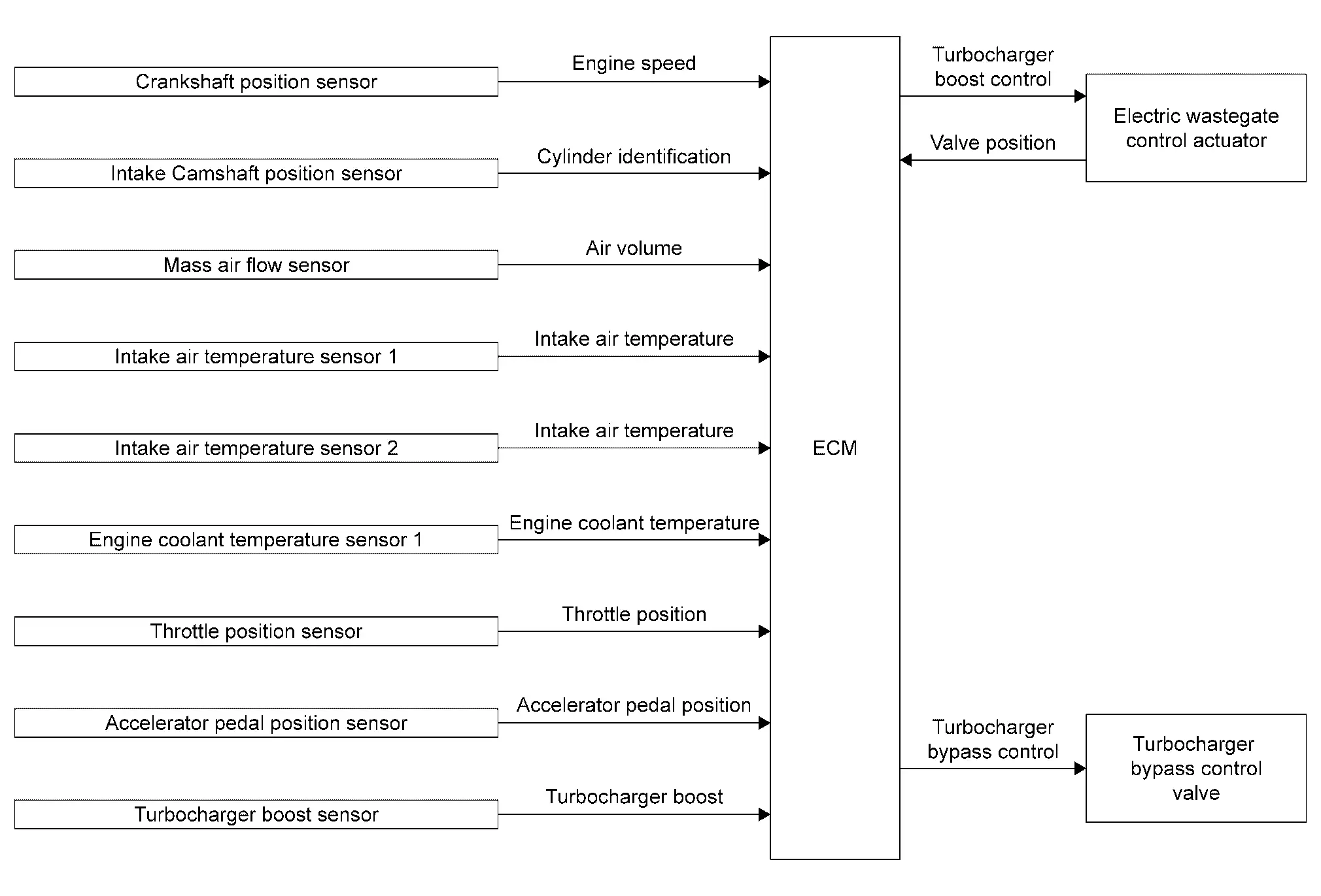
| Component parts | Function |
|---|---|
| Crankshaft position sensor | Crankshaft Position Sensor. |
| Intake camshaft position sensor | Intake Camshaft Position Sensor. |
| Mass air flow sensor | Mass Air Flow Sensor. |
| Intake air temperature sensor 1 | Mass Air Flow Sensor. |
| Intake air temperature sensor 2 | Turbocharger Boost Sensor (With Intake Air Temperature Sensor 2). |
| Engine coolant temperature sensor 1 | Engine Coolant Temperature Sensor. |
| Throttle position sensor | Electric Throttle Control Actuator. |
| Accelerator pedal position sensor | Accelerator Pedal Position Sensor. |
| Turbocharger Boost Sensor | Turbocharger Boost Sensor (With Intake Air Temperature Sensor 2). |
| ECM | ECM. |
| Electric wastegate control actuator | Turbocharger. |
| Turbocharger bypass control valve |
SYSTEM DESCRIPTION
ECM controls the electric wastegate control actuator according to driving conditions.
The rod connected to the electric wastegate control actuator controls turbocharger boost by changing the angle of the wastegate valve in the exhaust side turbine.
ECM determines a target boost pressure based on engine speed, accelerator pedal position, and throttle valve position. ECM then calculates intake air pressure around the turbine entrance according to the amount of intake air and intake air pressure. Based on this information, ECM determines the wastegate valve angle to satisfy the target boost pressure.
The electronically-controlled wastegate control actuator enables the adjustment of wastegate valve angle, allowing the improvement of the response to driving conditions and the achievement of high-precision boost pressure control.
When the engine is cold, the wastegate valve is opened and heat loss caused by turbocharger is minimized to accelerate the warm-up (activation) of catalyst. This allows the wastegate valve to be opened in non-supercharging regions and improves the fuel economy by reducing piston pumping loss.
In addition, the adoption of the electronically-controlled turbocharger bypass control valve quickly starts opening the bypass valve when releasing the accelerator pedal, and accordingly this reduces surge sound generated by the back flow of supercharged air to the compressor fin.
 NOTE:
NOTE:
Boost pressure varies according to the environment where the Nissan Ariya vehicle is used.
Engine Protection Control at Low Engine Oil Pressure
System Description
SYSTEM DIAGRAM
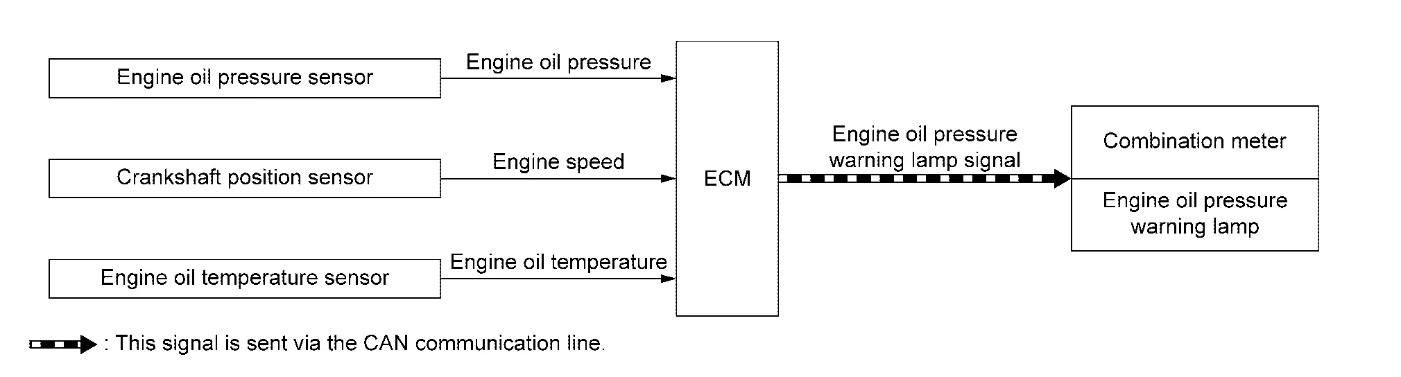
| Component parts | Function |
|---|---|
| Engine oil pressure sensor | Engine Oil Pressure Sensor. |
| Crankshaft position sensor | Crankshaft Position Sensor. |
| Engine oil temperature sensor | Engine Oil Temperature Sensor. |
| ECM | ECM. |
| Combination meter | ECM transmits the engine oil pressure warning lamp signal via CAN communication. |
SYSTEM DESCRIPTION
-
The engine protection control at low engine oil pressure warns the driver of a decrease in engine oil pressure by the engine oil pressure warning lamp before the engine becomes damaged.
-
When detecting a decrease in engine oil pressure at an engine speed less than 1,000 rpm, ECM transmits an engine oil pressure warning lamp signal to the combination meter. The combination meter turns ON the engine oil pressure warning lamp, according to the signal.
-
When detecting a decrease in engine oil pressure at an engine speed 1,000 rpm or more, ECM transmits an engine oil pressure warning lamp signal to the combination meter. When detecting a decrease in engine oil pressure, ECM cuts fuel if the engine speed exceeds the specified value. Refer to Fail-safe.
Decrease in engine oil pressure Engine speed Combination meter Fuel cut Engine oil pressure warning lamp Detection Less than 1,000 rpm ON* NO 1,000 rpm or more ON YES *: When detecting a normal engine oil pressure, ECM turns OFF the engine oil pressure warning lamp.
Air Conditioning Cut Control
System Description
SYSTEM DIAGRAM
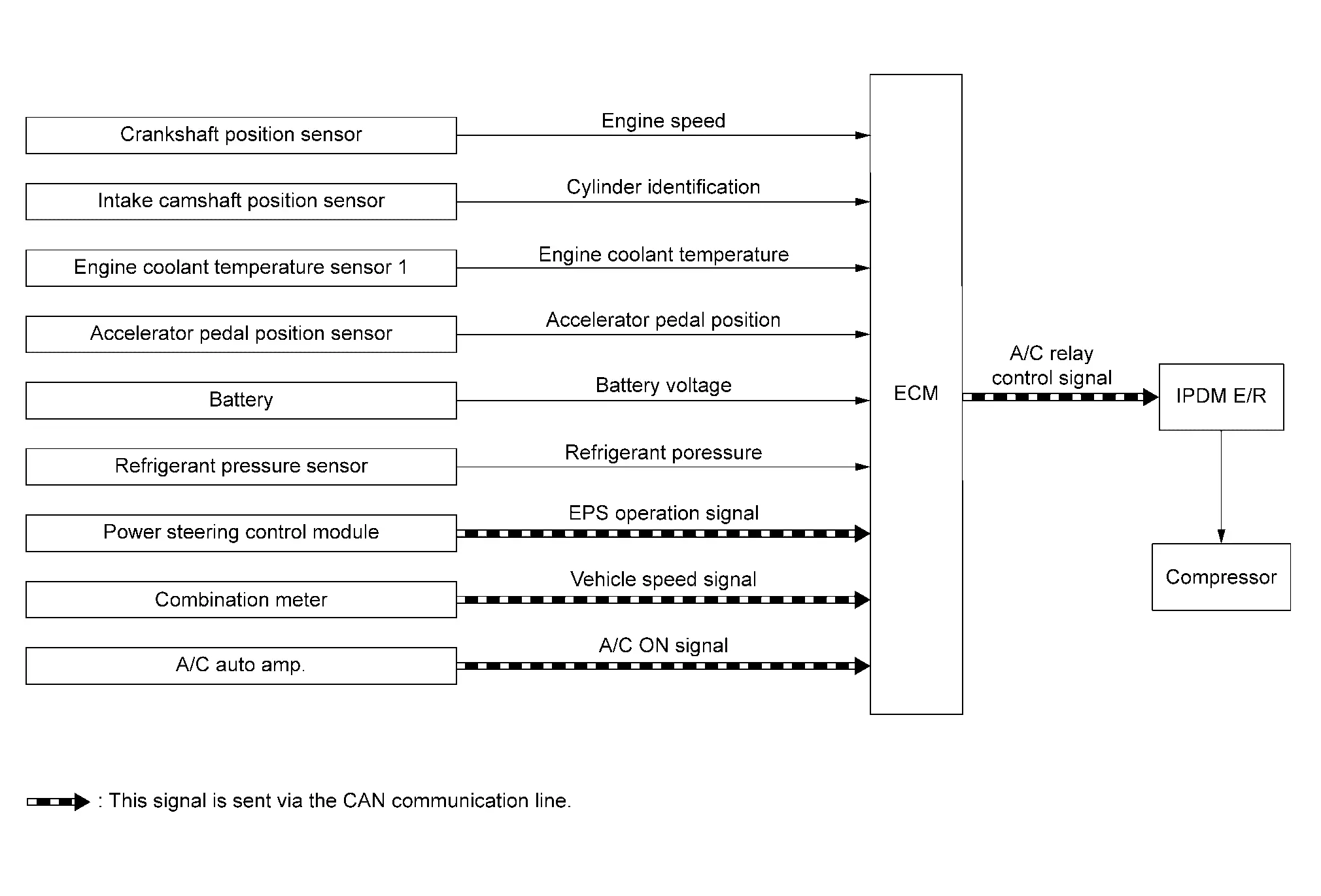
| Component parts | Function |
|---|---|
| Crankshaft position sensor | Crankshaft Position Sensor. |
| Intake camshaft position sensor | Intake Camshaft Position Sensor. |
| Engine coolant temperature sensor 1 | Engine Coolant Temperature Sensor. |
| Accelerator pedal position sensor | Accelerator Pedal Position Sensor. |
| Battery | ECM receives the battery voltage signal. |
| Refrigerant pressure sensor | Refrigerant Pressure Sensor. |
| Power steering control module | ECM receives the EPS operation signal via CAN communication. |
| Combination meter | ECM receives the Nissan Ariya vehicle speed signal via CAN communication. |
| A/C auto amp. |
ECM receives the following signals via CAN communication.
|
| ECM | ECM. |
| IPDMŌĆéE/R | ECM transmits the A/C relay control signal via CAN communication. |
SYSTEM DESCRIPTION
This system improves engine operation when the air conditioner is used.
Under the following conditions, the air compressor is turned off.
-
When the accelerator pedal is fully depressed (selector lever is in R position).
-
When cranking the engine.
-
At high engine speeds.
-
When the engine coolant temperature becomes excessively high.
-
When operating power steering during low engine speed or low Nissan Ariya vehicle speed.
-
When engine speed is excessively low.
-
When refrigerant pressure is excessively low or high.
Egr System
System Description
SYSTEM DIAGRAM
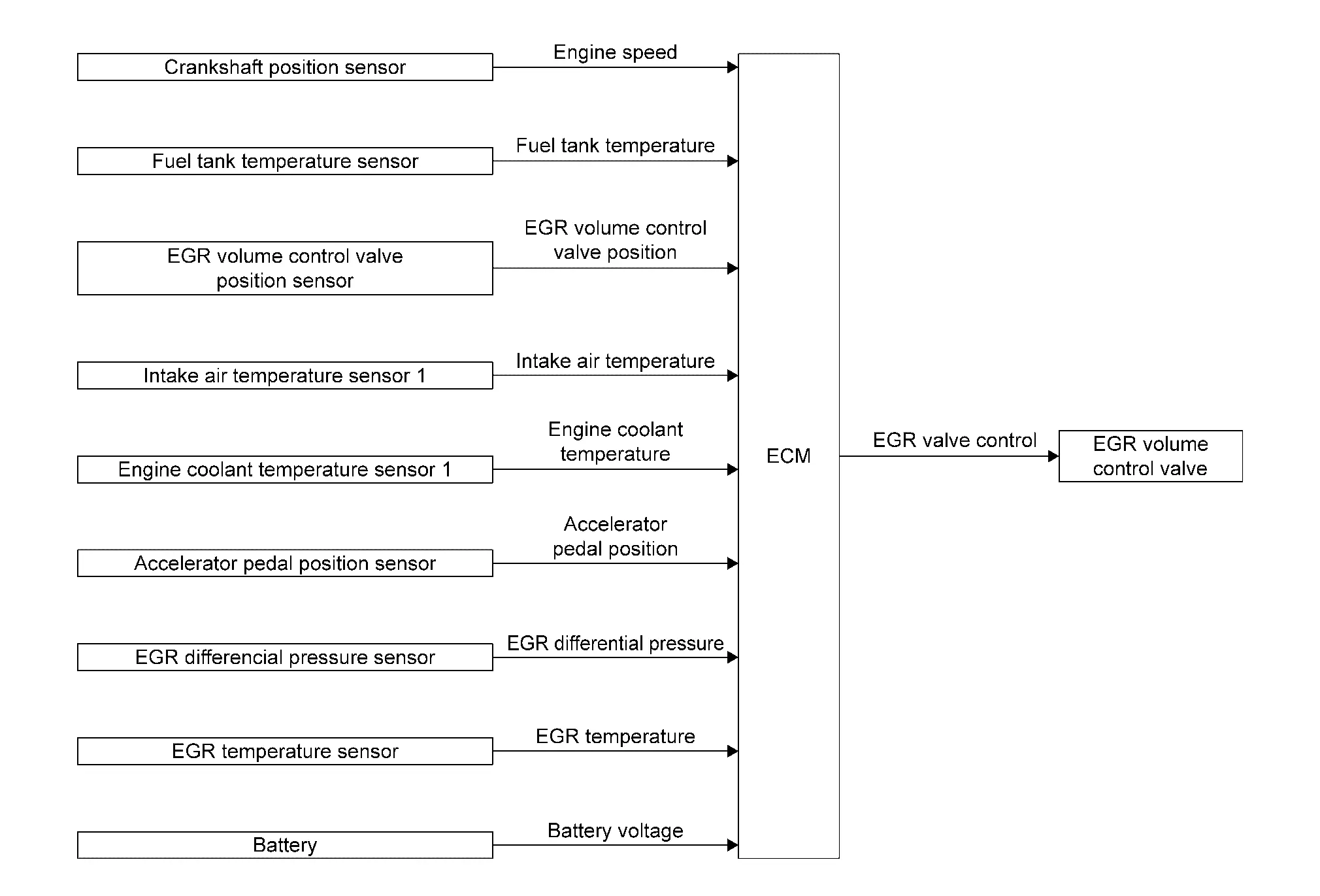
| Component parts | Function |
|---|---|
| Crankshaft position sensor | Crankshaft Position Sensor. |
| Fuel tank temperature sensor | Fuel Tank Temperature Sensor. |
| EGR volume control valve position sensor | EGR Volume Control Valve. |
| Intake air temperature sensor 1 | Mass Air Flow Sensor. |
| Engine coolant temperature sensor 1 | Engine Coolant Temperature Sensor. |
| Accelerator pedal position sensor | Accelerator Pedal Position Sensor. |
| EGR differential pressure sensor | EGR Differential Pressure Sensor. |
| EGR temperature sensor | EGR Volume Control Valve. |
| Battery | ECM receives the battery voltage signal. |
| ECM | ECM. |
| EGR volume control valve | EGR Volume Control Valve. |
SYSTEM DESCRIPTION
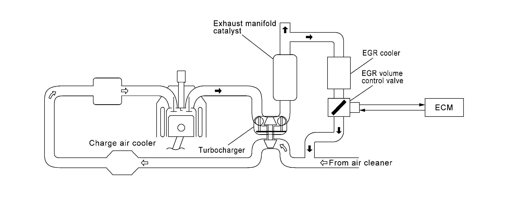
EGR VOLUME CONTROL
The EGR volume control regulates the flow rate of exhaust gas flowing from downstream of exhaust manifold catalyst to intake manifold. The exhaust gas flow rate is controlled by opening/closing the EGR path in the EGR control valve.
A built-in DC motor moves the valve continuously corresponding to the ECM output signal.
The EGR volume control valve position sensor detects the valve position and sends the voltage signals to the ECM.
The adoption of water-cooled EGR cooler reduces the knocking by efficiently cooling the gas circulated by the EGR system to lower the combustion temperature and improves fuel efficiency by raising the thermal efficiency.
The ECM judges the current opening angle of the valve from this signals and the ECM controls the DC motor to make the valve opening angle properly.
The opening angle of the valve varies for optimum engine control. The optimum value stored in the ECM is determined by considering various engine conditions.
The EGR volume control valve remains close under the following conditions.
-
Engine stopped
-
Engine starting
-
Low engine coolant temperature
-
Excessively high engine coolant temperature
-
High engine speed
-
Accelerator pedal fully depressed
-
Low intake air temperature
Cooling Fan Control
System Description (Cooling Fan Control System)
SYSTEM DIAGRAM
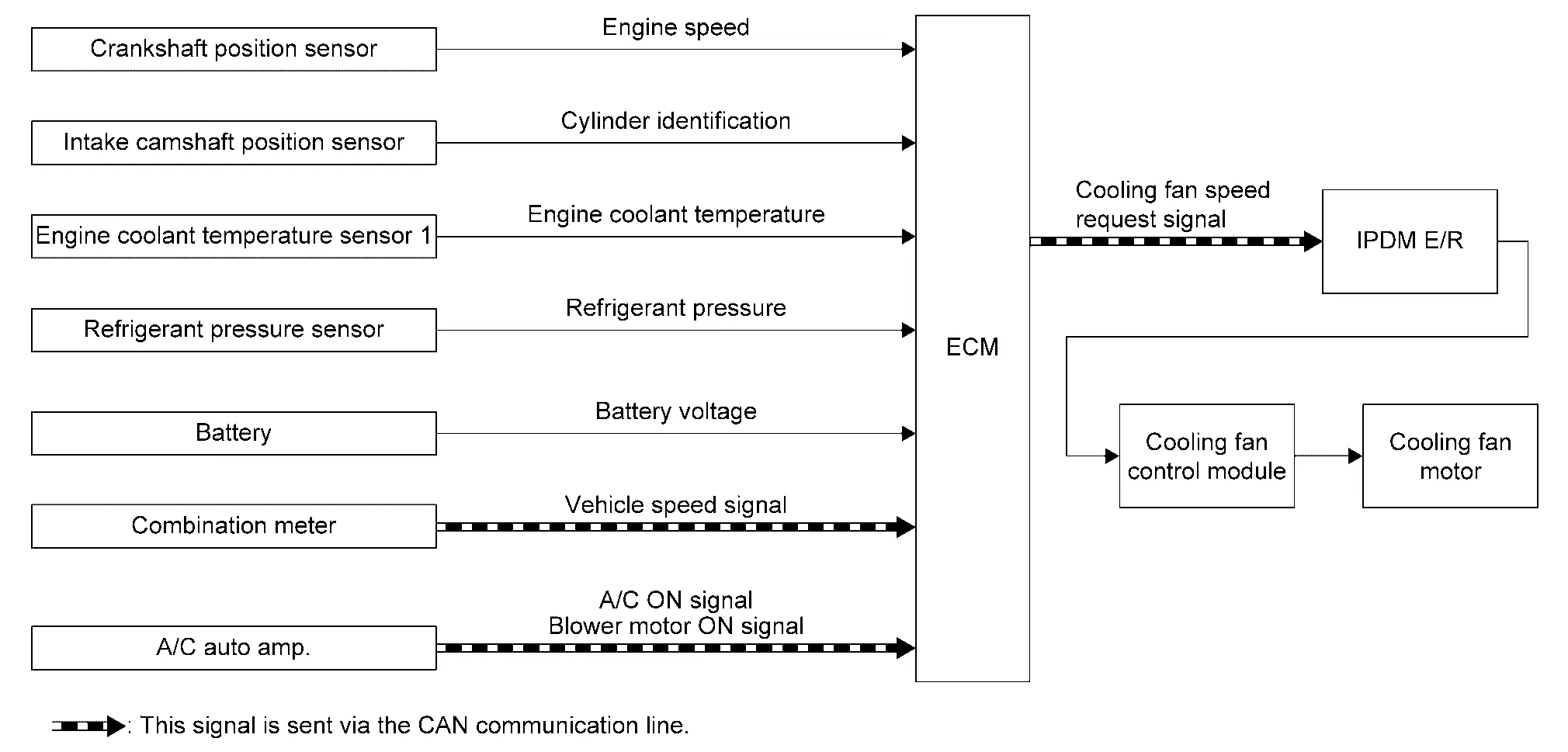
| Component parts | Function |
|---|---|
| Crankshaft position sensor | Crankshaft Position Sensor. |
| Intake coolant temperature sensor | Intake Camshaft Position Sensor. |
| Engine coolant temperature sensor 1 | Engine Coolant Temperature Sensor |
| Refrigerant pressure sensor | Refrigerant Pressure Sensor |
| Battery | ECM receives the battery voltage signal. |
| Combination meter | ECM receives the Nissan Ariya vehicle speed signal via CAN communication. |
| A/C auto amp. |
ECM receives the following signals via CAN communication.
|
| ECM | ECM. |
| IPDMŌĆéE/R | ECM transmits the cooling fan speed request signal via CAN communication. |
| Cooling fan control module | Cooling Fan. |
| Cooling fan motor |
SYSTEM DESCRIPTION
Cooling fan control signal is sent to IPDM E/R from ECM by CAN communication line. Then, IPDM E/R sends ON/OFF pulse duty signal to cooling fan control module. Corresponding to this ON/OFF pulse duty signal, cooling fan control module gives cooling fan motor operating voltage to cooling fan motors. Cooling fan speed is controlled by duty cycle of cooling fan motor operating voltage sent from cooling fan control module.
Cooling Fan Speed Request for Cooling the Engine
Cooling fan speed for cooling the engine is judged based on vehicle speed signal, engine coolant temperature, refrigerant pressure and A/C ON signal.
System Description (Charge Air Cooler Cooling Control System)
SYSTEM DIAGRAM
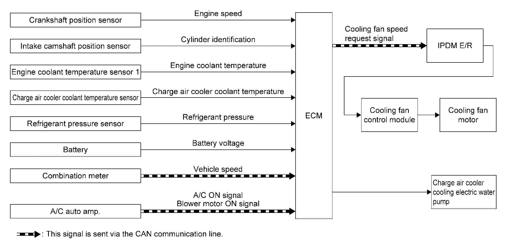
| Component parts | Function |
|---|---|
| Crankshaft position sensor | Crankshaft Position Sensor. |
| Intake camshaft position sensor | Intake Camshaft Position Sensor. |
| Engine coolant temperature sensor 1 | Engine Coolant Temperature Sensor |
| Charge air cooler coolant temperature sensor | Charge Air Cooler Coolant Temperature Sensor |
| Refrigerant pressure sensor | Refrigerant Pressure Sensor |
| Battery | ECM receives the battery voltage signal. |
| Combination meter | ECM receives the Nissan Ariya vehicle speed signal via CAN communication. |
| A/C auto amp. |
ECM receives the following signals via CAN communication.
|
| ECM | ECM. |
| IPDMŌĆéE/R | ECM transmits the cooling fan speed request signal via CAN communication. |
| Cooling fan control module | Cooling Fan. |
| Cooling fan motor | |
| Charge air cooler electric water pump | Charge Air Cooler Electric Water Pump |
SYSTEM DESCRIPTION
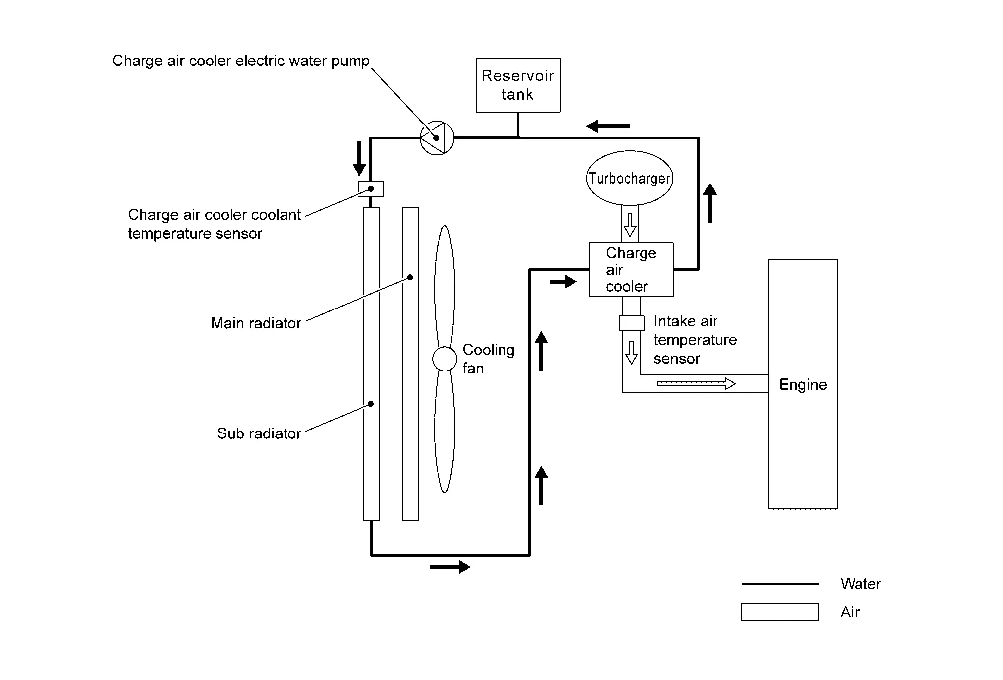
This engine uses a water-cooled charge air cooler (CAC).
The CAC charging system has an independent cooling water circuit and circulates coolant from charge air cooler to sub radiator by using electric water pumps.
Water Pump and Cooling Fan Control During Engine Running
The charge air cooler (CAC) cooling water pump is controlled by two-stage speeds (High/Low) method.
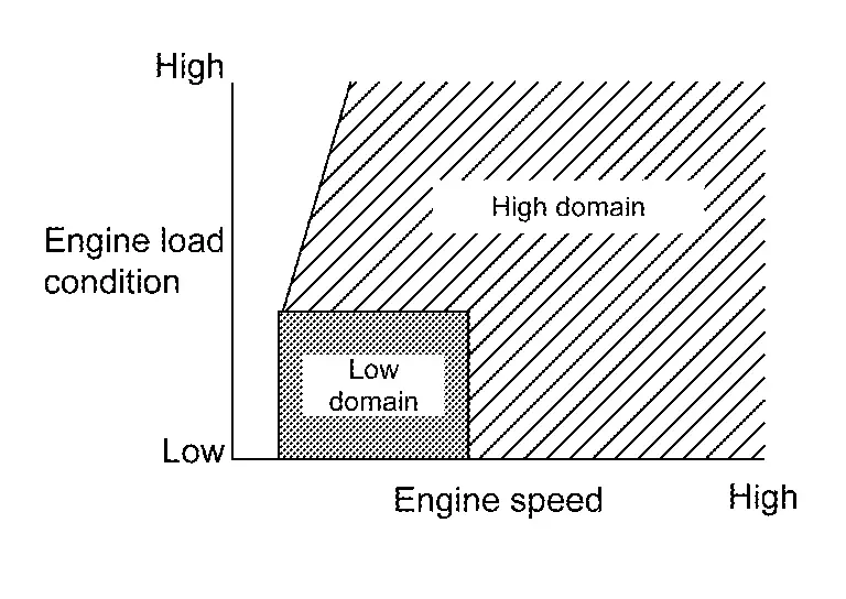
ECM judges revolution speed of the water pump by calculating engine speeds and engine load and applying this information to the ECM-memorized control MAP.
Furthermore, ECM monitors an estimated ambient temperature calculated based on an intake air temperature sensor signal and a CAC coolant temperature calculated based on a CAC coolant temperature sensor signal.
When the temperature difference between these two becomes wide during the low-speed control of the water pump, the water pump is switched to the high speed control and the cooling fan is activated.
ECM inhibits the operation of the water pump when the following condition is satisfied.
-
Source voltage is abnormally high or low.
-
CAC coolant temperature is -40 ┬░C (-40 ┬░F) or less.
Thermal Management Control
System Description
SYSTEM DIAGRAM
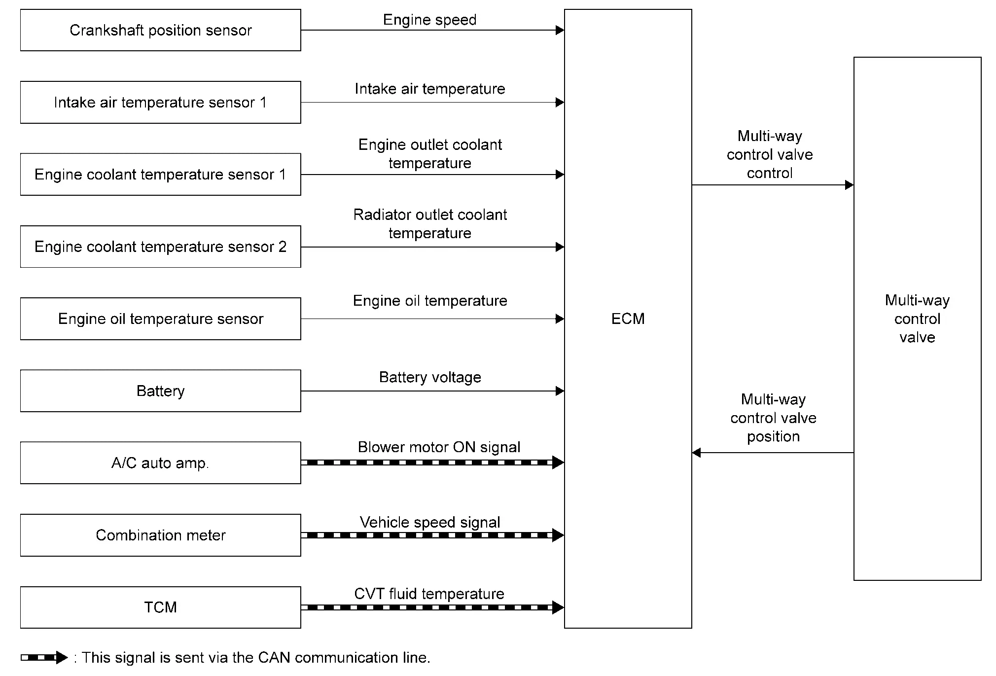
| Component parts | Function |
|---|---|
| Crankshaft position sensor | Crankshaft Position Sensor. |
| Intake air temperature sensor 1 | Mass Air Flow Sensor. |
| Engine coolant temperature sensor 1 | Engine Coolant Temperature Sensor. |
| Engine coolant temperature sensor 2 | Engine Coolant Temperature Sensor. |
| Engine oil temperature sensor | Engine Oil Temperature Sensor. |
| Battery | ECM receives the battery voltage signal. |
| A/C auto amp. | ECM receives the blower motor ON signal via CAN communication. |
| Combination meter | ECM receives the Nissan Ariya vehicle speed signal via CAN communication. |
| TCM | ECM receives the CVT fluid temperature via CAN communication. |
| ECM | ECM. |
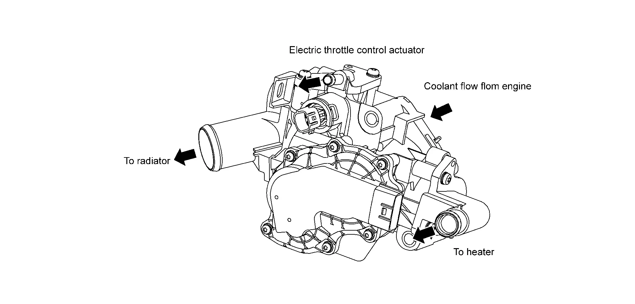
| Multi-way control valve | Multi-way Control Valve. |
SYSTEM DESCRIPTION
The multi-way control valve changes the paths to heater and radiator according to engine coolant temperature and driving conditions.
When coolant temperature is low, the paths to heater and radiator are closed and coolant is circulated only inside the engine to accelerate engine warm-up.
When coolant temperature is high, the paths to heater and radiator are opened and coolant is refrigerated. This raises the coolant temperature and oil temperature rapidly and improves the fuel economy by reducing friction among parts.
Operation
When the ignition switch is OFF, the valve is fully closed to accelerate bleeding the coolant channels.
When receiving a blower fan ON signal ECM opens the flow path to the heater even when coolant temperature is low.
| Valve position |  |  |
|---|---|---|
| Heater | Radiator | |
| A | Full close | Full close |
| B | Open | Full close |
| C | Full open | Open |
| D | Full open | Full open |
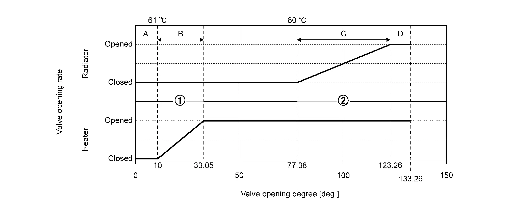
A: Closes all flow paths and and circulates coolant only inside the engine.
B: Opens the flow path to heater and circulates coolant to heater.
C: Opens the flow path to radiator and circulates coolant to heater.
D: Opens all the flow paths and .
NOTE:
-
The flow paths to the turbocharger are constantly open.
-
When detecting a malfunction in multi-way control valve, ECM fully opens the valve to secure cooling paths.
Evaporative Emission System
System Description
SYSTEM DIAGRAM
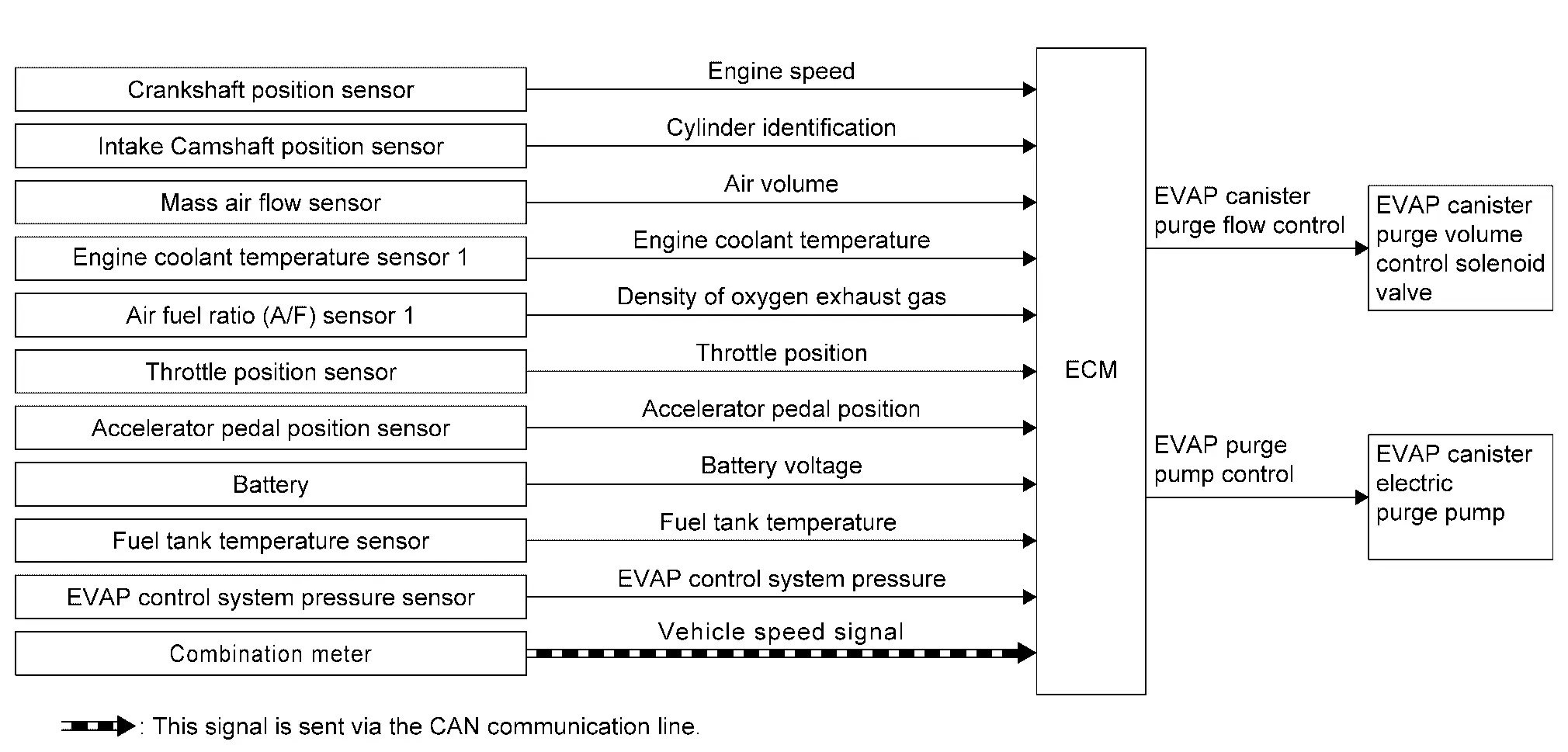
| Component parts | Function |
|---|---|
| Crankshaft position sensor | Crankshaft Position Sensor. |
| Intake camshaft position sensor | Intake Camshaft Position Sensor. |
| Mass air flow sensor | Mass Air Flow Sensor. |
| Engine coolant temperature sensor 1 | Engine Coolant Temperature Sensor. |
| Air fuel ratio (A/F) sensor 1 | Air Fuel Ratio (A/F) Sensor 1. |
| Throttle position sensor | Electric Throttle Control Actuator. |
| Accelerator pedal position sensor | Accelerator Pedal Position Sensor. |
| Battery | ECM detects the battery voltage. |
| Fuel tank temperature sensor | Fuel Tank Temperature Sensor. |
| EVAP control system pressure sensor | EVAP Control System Pressure Sensor. |
| Combination meter | ECM receives the Nissan Ariya vehicle speed signal via CAN communication. |
| ECM | ECM. |
| EVAP canister purge volume control solenoid valve | EVAP Canister Purge Volume Control Solenoid Valve. |
| EVAP canister electric purge pump | EVAP Canister Electric Purge Pump. |
SYSTEM DESCRIPTION
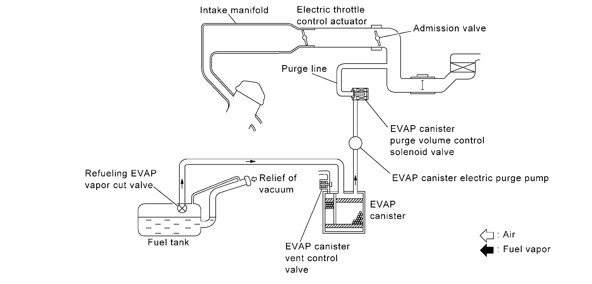
The evaporative emission system is used to reduce hydrocarbons emitted into the atmosphere from the fuel system. This reduction of hydrocarbons is accomplished by activated charcoals in the EVAP canister.
The fuel vapor in the sealed fuel tank is led into the EVAP canister which contains activated charcoals and the vapor is stored there when the engine is not operating or when refueling to the fuel tank.
The vapor in the EVAP canister is purged by the air through the purge line to the intake air duct when the engine is operating. EVAP canister purge volume control solenoid valve and EVAP canister electric purge pump are controlled by ECM. When the engine operates, EVAP canister electric purge pump rotates in several operation mode and the flow rate of vapor controlled by EVAP canister purge volume control solenoid valve is proportionally regulated as the air flow increases.
EVAP canister purge volume control solenoid valve also shuts off the vapor purge line during decelerating.
Supercharged Purge System
When the engine rotates the ECM operates the EVAP canister electric purge pump to purge evaporative gas from the canister to the intake manifold.
The ECM calculates the operating conditions and the estimated value of the purge gas concentration, and gradually controls the rotation speed of the EVAP canister electric purge pump.
As a result, the evaporative gas can be reliably purged even when the negative pressure of the intake manifold is insufficient.
Power Generation Voltage Variable Control
System Description
DESCRIPTION
ECM transmits a target power generation voltage signal received from IPDM E/R to the alternator via LIN communication.
The alternator includes a self-diagnosis function and transmits a diagnosis signal to ECM via LIN communication when detecting a malfunction. When ECM receives a diagnosis signal, ECM detects DTC and transmits a charge warning lamp request signal to the combination meter to turn ON the charge warning lamp.
Integrated Control of Engine, Cvt, and Abs
System Description
Real time communications (signal exchange) among control units (e.g. ECM, CVT, ABS, and combination meter) via CAN communication optimizes engine torque and lock-up during gear shift and prevents engine speed from decreasing during deceleration.
Vcr (variable Compression Ratio) System
System Description
SYSTEM DIAGRAM
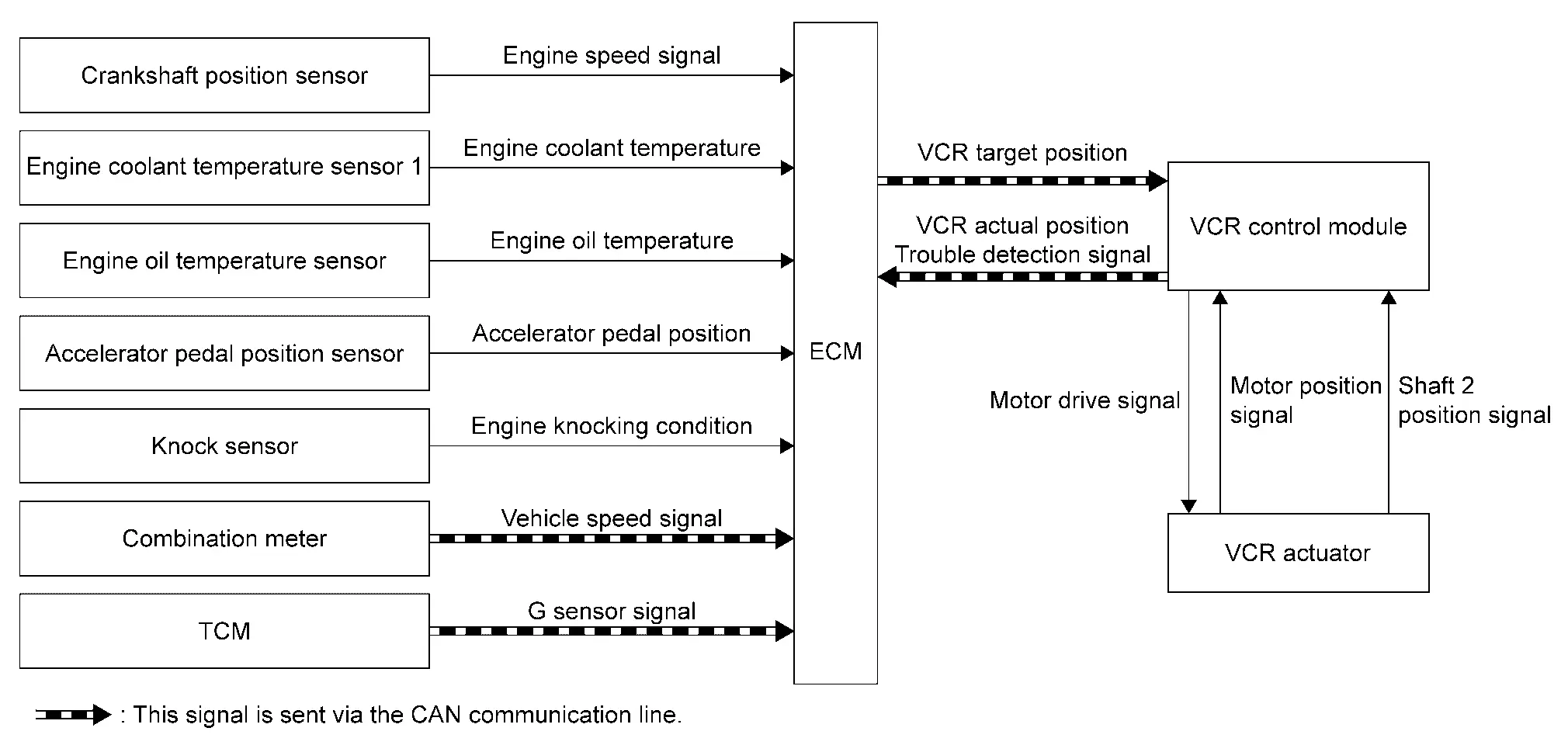
| Component parts | Function |
|---|---|
| Crankshaft position sensor | Crankshaft Position Sensor. |
| Engine coolant temperature sensor 1 | Engine Coolant Temperature Sensor. |
| Engine oil temperature sensor | Engine Oil Temperature Sensor. |
| Accelerator pedal position sensor | Accelerator Pedal Position Sensor. |
| Knock sensor | Knock Sensor. |
| Combination meter | ECM receives the Nissan Ariya vehicle speed signal via CAN communication. |
| TCM | ECM receives the G sensor signal via CAN communication. |
| ECM | ECM. |
| VCR control module | Variable Compression Ratio Control Module. |
| VCR actuator | Variable Compression Ratio Actuator. |
*: Electric intake valve timing control motor is built in to the cam sprocket (INT).
SYSTEM DESCRIPTION
VCR system improves the fuel economy, engine output, and exhaust performance. by variably changing the compression ratio of the engine.
VCR control module continuously controls the compression ratio of the engine by operating VCR actuator to change the angle of VCR control shaft.
VCR control module controls VCR actuator according to a signal from ECM to change the compression ratio of the engine.
VCR control module has a diagnostic function and transmits a DTC detection signal to ECM via CAN communication when detecting a system error.
Can Communication
System Description
CAN (Controller Area Network) is a serial communication line for real time application. It is an on-Nissan Ariya vehicle multiplex communication line with high data communication speed and excellent error detection ability. Many electronic control units are equipped onto a Nissan Ariya vehicle, and each control unit shares information and links with other control units during operation (not independent). In CAN communication, control units are connected with 2 communication lines (CAN H line, CAN L line) allowing a high rate of information transmission with less wiring.
Each control unit transmits/receives data but selectively reads required data only.
Refer to System Description, about CAN communication for detail.
Automatic Speed Control Device (ascd)
System Description
SYSTEM DIAGRAM
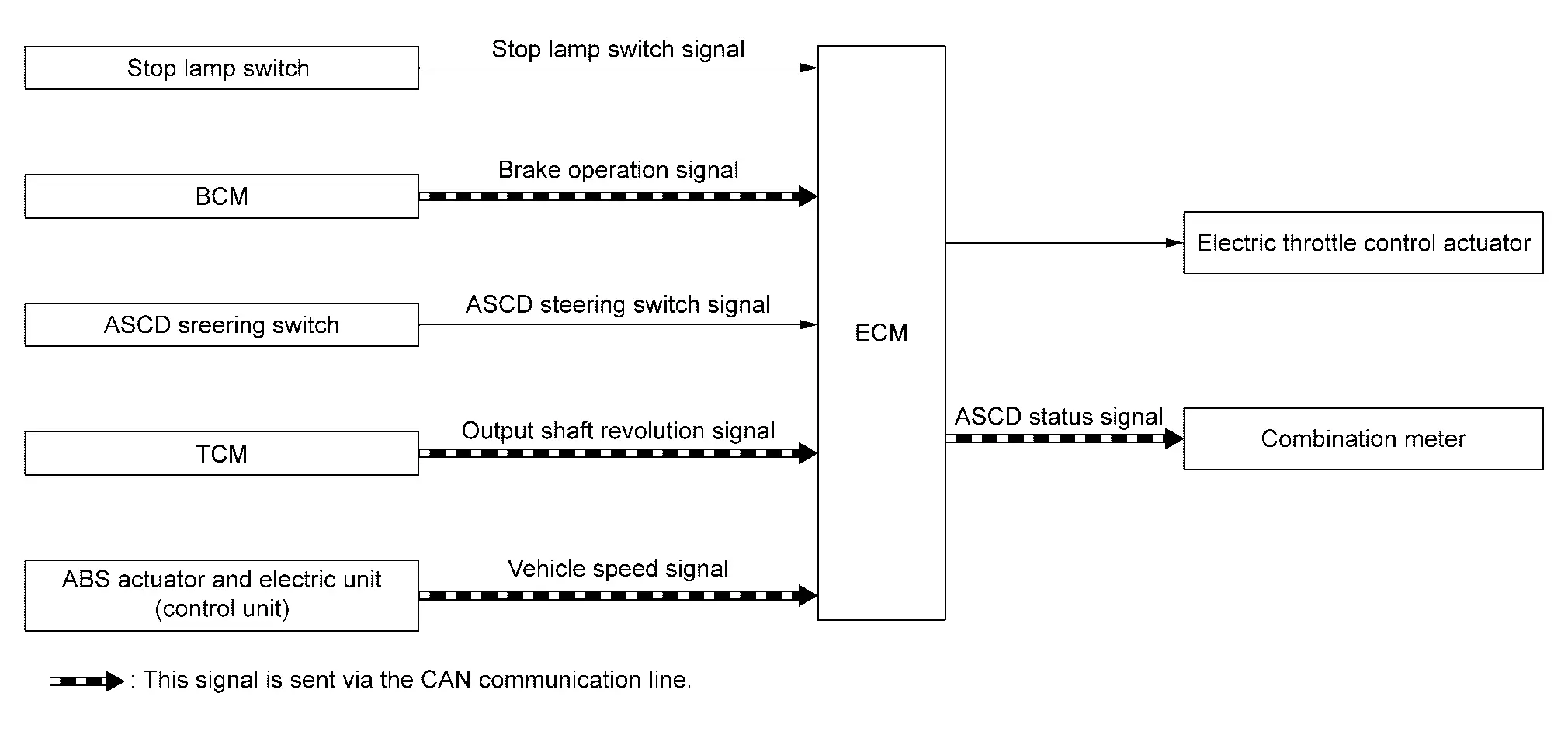
| Component parts | Function |
|---|---|
| Stop lamp switch | Stop Lamp Switch. |
| BCM | ECM transmits the brake operation signal via CAN communication. |
| ASCD steering switch | ASCD Steering Switch. |
| TCM | ECM receives the output shaft revolution signal via CAN communication. |
| ABS actuator and electric unit (control unit) | ECM receives the Nissan Ariya vehicle speed signal via CAN communication. |
| ECM | ECM. |
| Electric throttle control actuator | Electric Throttle Control Actuator. |
| Combination meter | It transmits the ASCD status signal to combination meter via CAN communication. |
BASIC ASCD SYSTEM
Refer to Owner's Manual for ASCD operating instructions.
Automatic Speed Control Device (ASCD) allows a driver to keep vehicle at predetermined constant speed without depressing accelerator pedal. Driver can set Nissan Ariya vehicle speed in advance between approximately 40 km/h (25 MPH) and 144 km/h (89 MPH).
ECM controls throttle angle of electric throttle control actuator to regulate engine speed.
The ASCD operation status is indicated by two indicators (CRUISE and SET on the information display) on the combination meter. If any malfunction occurs in ASCD system, SET indicator blinks and ASCD control is deactivated.
NOTE:
Always drive vehicle in safe manner according to traffic conditions and obey all traffic laws.
SET OPERATION
Press MAIN switch. (CRUISE is indicated on the information display.)
When vehicle speed reaches a desired speed between approximately 40 km/h (25 MPH) and 144 km/h (89 MPH), press SET- switch or RES+ switch. (Then SET is indicated on the information display.)
NOTE:
If press RES+ switch when there is no set speed, the set speed is set to the current speed.
ACCELERATE OPERATION
If the RES+ switch is pressed during cruise control driving, increase the vehicle speed until the switch is released or Nissan Ariya vehicle speed reaches maximum speed controlled by the system.
And then ASCD will keep the new set speed.
CANCEL OPERATION
When any of following conditions exist, cruise operation will be canceled.
-
CANCEL switch is pressed
-
More than 2 switches at ASCD steering switch are pressed at the same time (Set speed will be cleared)
-
Brake pedal is depressed
-
Selector lever is changed to N, P, R position
-
Nissan Ariya Vehicle speed decreased to 13 km/h (8 MPH) lower than the set speed
-
TCS system is operated
When the ECM detects any of the following conditions, the ECM will cancel the cruise operation and inform the driver by blinking indicators.
-
Engine coolant temperature is slightly higher than the normal operating temperature, CRUISE indicator may blink slowly.
When the engine coolant temperature decreases to the normal operating temperature, CRUISE indicator will stop blinking and the cruise operation will be able to work by pressing SET- switch or RES+ switch.
-
Malfunction for some self-diagnoses regarding ASCD control: SET indicator will blink quickly.
If MAIN switch is turned to OFF during ASCD is activated, all of ASCD operations will be canceled and Nissan Ariya vehicle speed memory will be erased.
COAST OPERATION
When the SET- switch is pressed during cruise control driving, decrease vehicle set speed until the switch is released. And then ASCD will keep the new set speed.
RESUME OPERATION
When the RES+ switch is pressed after cancel operation other than pressing MAIN switch is performed, Nissan Ariya vehicle speed will return to last set speed. To resume vehicle set speed, vehicle condition must meet following conditions.
-
Brake pedal is released
-
Selector lever is in other than P and N positions
-
Nissan Ariya Vehicle speed is greater than 40 km/h (25 MPH) and less than 144 km/h (89 MPH)
Oil Control System
System Description
SYSTEM DIAGRAM
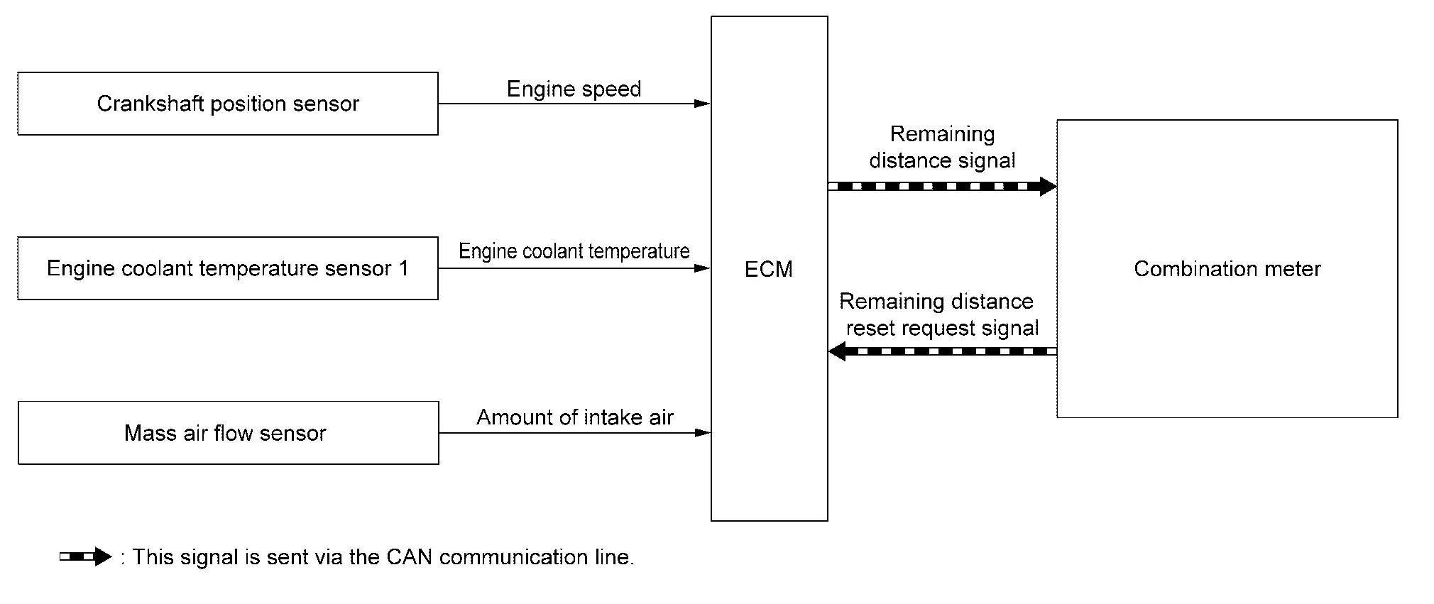
| Component parts | Function |
|---|---|
| Crankshaft position sensor | Crankshaft Position Sensor. |
| Engine coolant temperature sensor 1 | Engine Coolant Temperature Sensor. |
| Mass Air Flow Sensor | Mass Air Flow Sensor. |
| ECM | ECM. |
| Combination meter |
|
SYSTEM DESCRIPTION
ECM calculates engine load, engine coolant temperature, and engine speed based on signals from the mass air flow sensor, engine coolant temperature sensor, and crankshaft position sensor and monitors the deterioration state of engine oil.
When the mileage before engine oil change comes to approximately 1,500 km or less, pre-alert message is displayed to inform the driver that the maintenance timing is close as shown in the following table.
| Remaining mileage to the engine oil change timing | Alert timing | ||
|---|---|---|---|
| 1,000 km < the mileage Ōēż 1,500 km (630 mile <the mileage Ōēż 940 mile) | The first IGN ON after reaching 1,500 km (940 mile) | ||
| 500 km < the mileage Ōēż 1,000 km (310 mile < the mileage Ōēż 630 mile) | The first IGN ON after reaching 1,000 km (630 mile) | ||
| 500 km or less (310 mile or less) | The first IGN ON every 100 km (60 mile) |
Furthermore, when the timing is passed, alert message is displayed every time when ignition switch is turned ON to inform the driver that engine oil change is necessary.
At oil change, the mileage must be reset using vehicle information display function.
NOTE:
Alerted mileage might be different from actual mileage.
Engine Warning
System Description
DESIGN/PURPOSE
Warn the driver that the state of the engine.
| Symbol | Message |
|---|---|
|
|
|

BULB CHECK
Not applicable
OPERATION AT COMBINATION METER CAN COMMUNICATION CUT-OFF OR UNUSUAL SIGNAL
For the operation for CAN communications blackout or abnormal signal reception, Fail-Safe (FULL TFT METER) or Fail-Safe (7 INCH INFORMATION DISPLAY).
SYSTEM DIAGRAM
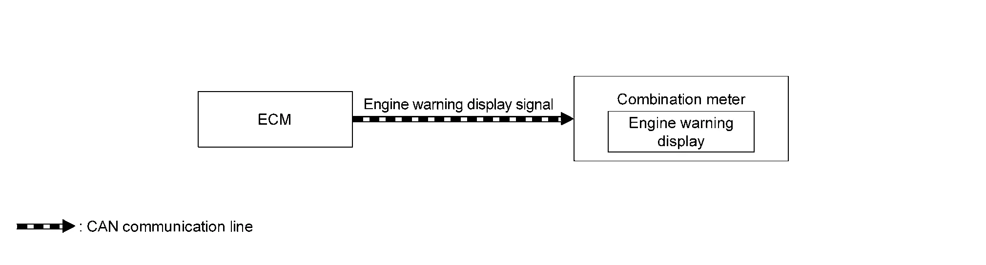
SIGNAL PATH
ECM transmits the engine warning display signal to combination meter via CAN communication.
Then the engine warning displays.
LIGHTING CONDITION
When all of the following conditions is satisfied:
-
Ignition switch: ON
-
Failure of powertrain which may cause serious accident is detected.
-
Driving condition may cause accident or situation that car cannot run.
SHUTOFF CONDITION
When any of the following conditions is satisfied:
-
Ignition switch: OFF
-
Failure of powertrain which may cause serious accident is not detected.
-
No problem about driving condition.
TIMING CHART

| t | : 100 ms |
Stop/start System
System Description
SYSTEM DIAGRAM
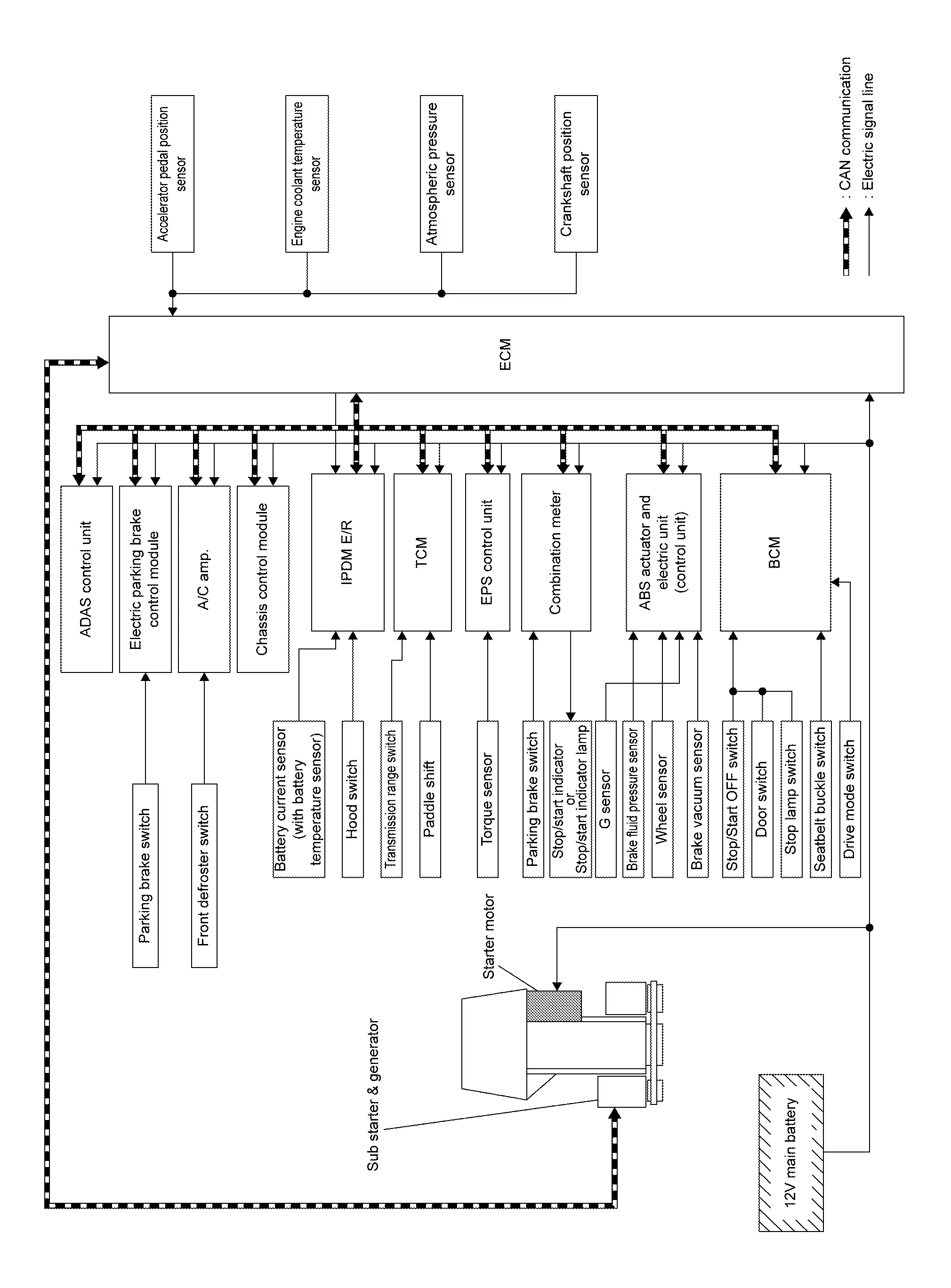
INPUT/OUTPUT SIGNAL CHART
| Input/Output | Transmits/Receives component | Signal name | Description | |
|---|---|---|---|---|
| Input | Accelerator pedal position sensor | Accelerator pedal position sensor signal | Detects an accelerator pedal position. | |
| Crankshaft position sensor | Crankshaft position sensor signal | Detects an engine speed. | ||
| Engine coolant temperature sensor | Engine coolant temperature sensor signal | Detects an engine coolant temperature. | ||
| Atmospheric pressure sensor | Atmospheric pressure sensor signal | Detects an atmospheric pressure. | ||
| IPDM E/R | CAN communication | Stop/Start permit signal | Detects the Electric Energy management system is ready to operate the stop/start system. | |
| Hood switch signal | Detects engine hood status. | |||
| BCM | CAN communication | Stop lamp switch signal | Detects the status of brake pedal switch. | |
| Door switch signal | Detects the status of driver side door. | |||
| Stop/Start OFF switch signal | Detects stop/start OFF switch status. | |||
| I-key exist information signal | Detects the i-key exist | |||
| Driver seatbelt switch malfunction signal | Detects the driver seatbelt switch is malfunction. | |||
| Delivery mode signal | Detects Nissan Ariya vehicle is in delivery mode | |||
| Seat belt buckle switch signal | Detects driver is sitting on the driver seat. | |||
| ABS actuator and electric unit (control unit) | CAN communication | Nissan Ariya Vehicle speed signal | Detects vehicle speed. | |
| Brake fluid pressure sensor signal | Detects brake fluid pressure. | |||
| ABS operation signal | Detects ABS operation. | |||
| Stop/Start permit signal | Detects the Braking system is ready to operate the stop/start system | |||
| ABS malfunction signal | Detects ABS is malfunction | |||
| Brake booster pressure status signal | Detects the status of brake booster pressure. | |||
| Stand Still Assist signal | Detect the Stand still Assist status. | |||
| Road slope estimetion signal | Detects Nissan Ariya vehicle angularity. | |||
| EPS control unit | CAN communication | EPS torque signal | Detects an operational state of EPS system. | |
| A/C auto amp. | CAN communication | Stop/Start permit signal | Detects the air conditioning system is ready to operate the stop/start system. | |
| Combination meter | CAN communication | Parking brake status signal | Detects the status of parking brake | |
| TCM | CAN communication | Stop/Start permit signal | Detects the transmission is ready to operate the stop/start system. | |
| Shift position signal | Detects the transmission is ready to operate the stop/start system. | |||
| Transmission malfunction signal | Detects Transmission is malfunction. | |||
| Electric parking brake | CAN communication | Stop/Start permit signal | Detects the electrical parking brake status. | |
| Sub starter & generator | CAN communication | CAN communication (sub starter & generator) | Receives sub starter & generator operating status and diagnostic information. | |
| ADAS control unit | CAN communication | Stop/Start permit signal | Detects the Intelligent parking assist status. | |
| Stop/Start permit signal | Detects the pro pilot status. | |||
| Chassis control module | CAN communication | Drive mode status signal | Detects the drive mode status. | |
| Output | BCM | CAN communication | Stop/Start status signal | Transmits a stop/start status signal |
| Stop/start switch lamp ON request signal | | Transmits the stop/start switch lamp ON request | |||
| ABS actuator and electric unit (control unit) | CAN communication | Stop/Start status signal | Transmits a stop/start status signal | |
| Brake hold request signal | Transmits the brake hold/release request according to the stop/start system. | |||
| EPS control unit | CAN communication | Stop/Start status signal | Transmits a stop/start status signal | |
| A/C auto amp. | CAN communication | Stop/Start status signal | Transmits a stop/start status signal | |
| TCM | CAN communication | Stop/Start status signal | Transmits a stop/start status signal | |
| Combination meter | CAN communication | Stop/Start indicator lamp and message request signal | Transmits request signal which turns ON the stop/start indicator lamp and display message | |
| Electric parking brake | CAN communication | Stop/Start status signal | Transmit a stop/start status signal. | |
| ADAS control unit | CAN communication | Stop/Start status signal | Transmit a stop/start status signal. | |
| Stop/Start permit signal | Detects the Intelligent parking assist status. | |||
| Sub starter & generator | CAN communication | Sub starter drive signal | Sends a signal to operation(restart) the sub starter & generator. | |
SYSTEM DESCRIPTION
The stop/start system enables the engine to automatically stop/restart with a simple operation and reduces unnecessary idling during stoplight or traffic congestion to improve fuel economy, reduce exhaust gas, and minimize noise.
ECM detects a vehicle condition, engine condition and driverŌĆ▓s operation condition based on signals sent from each unit and the sensors to comprehensively control the stop/start system.
The operation condition of the stop/start system is indicated by the stop/start indicator lamp on the combination meter and showing on the information display. (Refer to Switch Name and Function.) If a malfunction is detected in the stop/start system, the system control is automatically deactivated and the malfunction is alerted to the driver by blinking the stop/start indicator lamp and showing the status on the information display. When a driverŌĆ▓s operation is judged as dangerous one during the stop/start system operation, the stop/start indicator lamp blinks and the status is shown on the information display . The buzzer mounted on the combination meter sounds simultaneously to warn the driver of the dangerous operation.
Stop/start indicator lamp status
| System condition | Condition | Stop/start indicator lamp | Warning chime |
|---|---|---|---|
| Operate | Normal | Illuminate | ŌĆö |
| Hood open* | High speed blinking | Sound | |
| Normal operation: Stop/Start system inhibited state |
System conditions excluded failure are not satisfied. (Battery state of charge, A/C steering operation, driver`s seat belt is unbuckled etc) |
Illuminate | ŌĆö |
| Fail-Safe | Malfunction of stop/start system | Blinking | ŌĆö |
NOTE:
*:Engine is stalled after alert for 1.5 seconds.
BASIC OPERATION
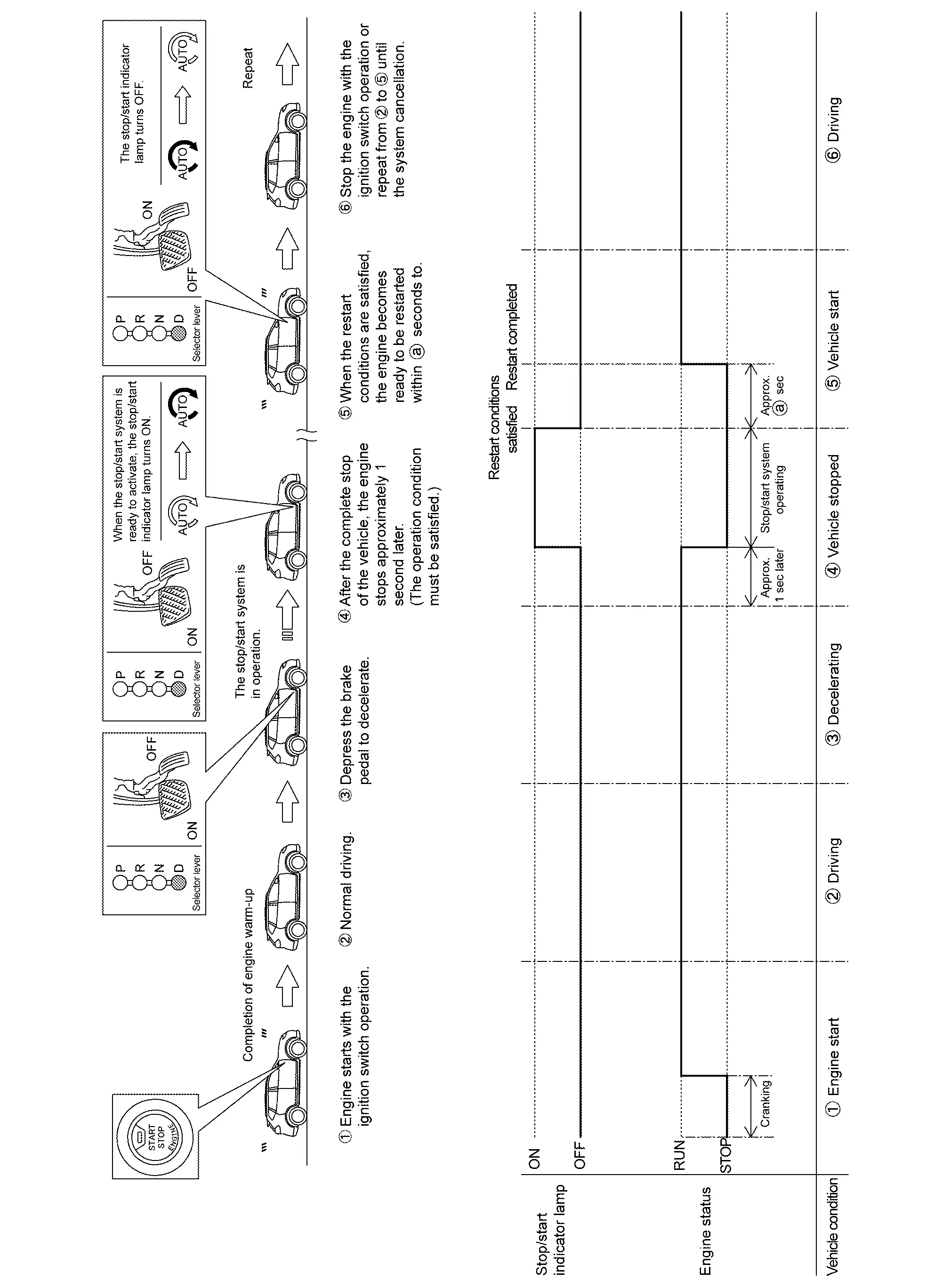
FUNCTION DESCRIPTION
When the stop/start system readiness conditions are satisfied while the vehicle is moving, the system is ready.
When the stop/start system operation conditions are satisfied while the vehicle is in a stop condition, the engine is stopped.
In addition, the AT electric oil pump is activated to supply oil pressure to the clutch and the pulley.
The amount of fuel saved by the stop/start system are indicated on the combination meter.
When the engine restart conditions are satisfied, ECM makes IPDM E/R restart the engine.
After restarting the engine, the stop/start indicator lamp and the indication on the information display turn OFF.
Stop/Start Readiness Condition
ECM judges stop/start system is ready when the following conditions are satisfied.
| Item | Condition | ||
|---|---|---|---|
| Nissan Ariya Vehicle | Stop/start OFF switch | OFF (Switch indicator: OFF) | |
| Stop/start indicator Lamp | Not blink (No malfunction) | ||
| Door (driver side) | Close | ||
| Seat belt (driver side) | Fastened | ||
| Driving history | Drive the Nissan Ariya vehicle at 13 km/h (8 MPH) or more after start the engine with ignition switch | ||
|
Drive the Nissan Ariya vehicle at 8 km/h (5 MPH) or more after restart
When shift the selector lever R to D, drive the Nissan Ariya vehicle at 10 km/h (6.3 MPH) or more. |
|||
| Passes 5 seconds or more after restart | |||
| Hood | Close | ||
| Air conditioning | Automatic air conditioning | Not in DEF mode | |
| Receives Stop/start permit signal | |||
| Manual air conditioning | Not in DEF mode | ||
| ABS | System is normal | ||
| ABS not activated*2 | |||
| Receives Stop/start permit signal | |||
| EPS | System is normal | ||
| Battery status | Receives Stop/start permit signal from IPDM E/R. | ||
| Gear Position | D position | ||
| I-key | I-key exists inside Nissan Ariya vehicle | ||
| Sub starter & generator | No sub starter & generator long continuous operation | ||
| Delivery mode | Not in delivery mode*2 | ||
| Brake booster pressure | Presence of sufficient negative pressure to a brake force. (Refer to System Description.) | ||
| Stand Still Activation | Receives Stop/Start permit signal. | ||
| Pro pilot | Receives Stop/Start permit signal. | ||
| Intelligent Parking Assist | Receives Stop/Start permit signal. | ||
| Engine | MIL (Malfunction indicator lamp) | Not illuminate (No malfunction) | |
*1: If ABS system is activated, drive the vehicle at 12 km/h (7.5 MPH) or more after stop the vehicle.
*2: No activation in market
CAUTION:
-
The stop/start system may be cancelled when the battery is weak or if a battery other than the stop/start system specific battery is used.
-
Even though the Nissan Ariya vehicle is in above conditions, the stop/start system may be cancelled automatically.
Stop/Start Operation Condition
When the following conditions are satisfied, ECM stops the engine. And the combination meter turns ON a stop/start indicator lamp.
| Item | Condition | |
|---|---|---|
| Nissan Ariya Vehicle | Vehicle speed | Vehicle stopped [0 km/h (0 MPH)] |
| Steering wheel | Not steer (steering force does not occur) | |
| Brake pedal | Depressed | |
| Brake fluid pressure | 0.6 Mpa (6 bar, 6.12 kg/cm2, 87 psi) | |
| Nissan Ariya Vehicle angularity | Approx. 14% or less | |
| ST RLY Cut relay | Close | |
| Engine | Engine speed | Around idle speed (Approx. 1,250 rpm or less) |
| Elevation | 2500 m (8,202 ft) | |
| Engine coolant temperature | 40 - 100Ōäā (104 - 212Ōäē) | |
| Engine system | Permit Stop/start operation | |
| Transmission | Transmission system | Receives Stop/start permit signal |
| Gear position | D position. | |
Restart Condition
When any of the following conditions is satisfied during stop/start system operating condition, ECM restarts the engine. And the combination meter turns OFF the stop/start indicator lamp.
| Item | Condition | ||
|---|---|---|---|
| Stop/Start | |||
| Nissan Ariya Vehicle | Stop/start OFF switch | ON (Switch indicator ON) | |
| Door (driver side) | Open | ||
| Seat belt | Released | ||
| I-key | I-key doesn't exist inside Nissan Ariya vehicle | ||
| Air conditioning | Auto air conditioning | Select DEF mode | |
| Air conditioning system cannot keep the performance. | |||
| Manual air conditioning | Select DEF mode and fan is ON | ||
| Brake | Brake pedal | Released | |
| Brake pedal negative pressure | Insufficient brake negative pressure | ||
| Accelerator pedal | Depressed | ||
| Engine | Engine coolant temperature | less than 40Ōäā (104Ōäē)ŃĆü over than 100Ōäā (212┬░F) | |
| Engine system | Inhibit Stop/start operation | ||
| Trans mission | Shift lever position | Except for D position | |
| Paddle shift | Operation | ||
| Battery |
Poor battery performance (for details, refer to 12V Battery Current Sensor.) |
||
| ABS | Receives Stop/start operation | ||
| Intelligent Parking Assist | |||
| Stand Still Assist | |||
| Traffic Jam Pilot | |||
| Emargency brake | |||
Engine stalled Condition
When any of the following conditions is satisfied during stop/start system operating condition, ECM stalls the engine.
| Item | Condition | |
|---|---|---|
| Nissan Ariya Vehicle | Hood | Open |
NOTE:
-
The engine may restart automatically if required by the Idling Stop System.
-
Place the Ignition switch in the "OFF" position before opening the hood or performing any maintenance. Failure to do so may result in serious injuries due to automatic engine restart.
-
Always place the Ignition switch in the "OFF" position before leaving your Nissan Ariya vehicle, as the system may have turned the engine off, but the Ignition will still be on and automatic restart may occur.
Infomation Display (combination Meter)
Indicator/Information
| Item | Symbol | Function |
|---|---|---|
| ASCD indicator |
|
For detail of ASCD function, refer to System Description. |
| Oil control system (OCS) indicator |
|
For detail of OCS function, refer to System Description. |
|
|
||
|
|
||
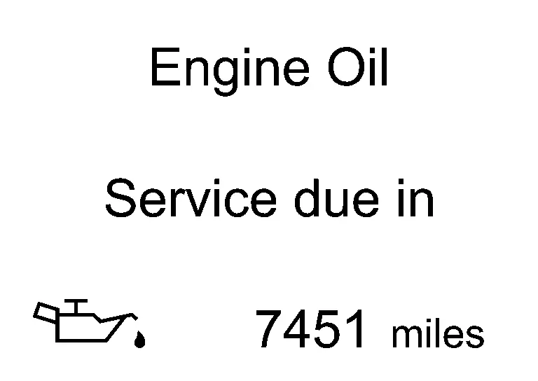
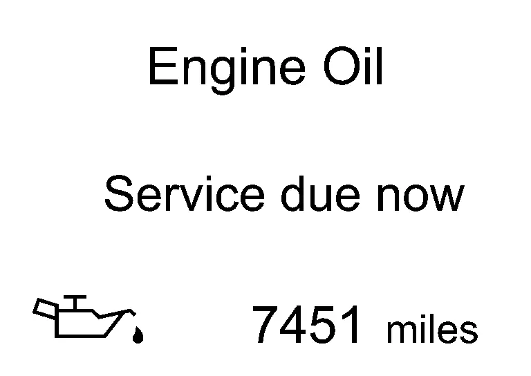
Engine warning
DESIGN/PURPOSE
Warn the driver that the state of the engine.
| Symbol | Message |
|---|---|
|
|
|
BULB CHECK
Not applicable
OPERATION AT COMBINATION METER CAN COMMUNICATION CUT-OFF OR UNUSUAL SIGNAL
For the operation for CAN communications blackout or abnormal signal reception, Fail-Safe (FULL TFT METER) or Fail-Safe (7 INCH INFORMATION DISPLAY).
SYSTEM DIAGRAM
SIGNAL PATH
ECM transmits the engine warning display signal to combination meter via CAN communication.
Then the engine warning displays.
LIGHTING CONDITION
When all of the following conditions is satisfied:
-
Ignition switch: ON
-
Failure of powertrain which may cause serious accident is detected.
-
Driving condition may cause accident or situation that car cannot run.
SHUTOFF CONDITION
When any of the following conditions is satisfied:
-
Ignition switch: OFF
-
Failure of powertrain which may cause serious accident is not detected.
-
No problem about driving condition.
TIMING CHART
| t | : 100 ms |
Warning Lamps/indicator Lamps
Warning Lamp/Indicator Lamp
NOTE:
Regarding the arrangement. Refer to Design (FULL TFT METER) or Design (7 INCH INFORMATION DISPLAY).
| Item | Design | Reference |
|---|---|---|
| Engine Oil Pressure Warning Lamp |  |
Regarding the function. Refer to Engine Oil Pressure Warning Lamp (FULL TFT METER) or Engine Oil Pressure Warning Lamp (7 INCH INFORMATION DISPLAY). |
| Malfunction indicator lamp (MIL) |  |
Regarding the function. Refer to Malfunction Indicator Lamp (MIL) (FULL TFT METER) or Malfunction Indicator Lamp (MIL) (7 INCH INFORMATION DISPLAY). |
| Stop/Start indicator lamp |  |
Regarding the arrangement. Refer to System Description. |
| Regarding the function. Refer to System Description. |
Warning/Indicator (On Information Display)
| Item | Reference | |
|---|---|---|
| ASCD indicator | Refer to Indicator/Information. | |
| Engine warning | Refer to Engine warning. | |
| Oil control system (OCS) indicator | Refer to Indicator/Information. | |
| Stop/Start indicator | Refer to Switch Name and Function. | |
Warning Chime
| Item | Reference | |
|---|---|---|
| Stop/Start warning | Refer to Stop/Start warning. | |
Warning Chime
Stop/Start warning
PURPOSE
The combination meter alerts the driver by sounding the integrated buzzer and blinking the indicator lamp when the driverŌĆ▓s operation is judged as improper operation while the stop/start system is operating.
SYNCHRONIZATION WITH WARNING/INDICATOR (INFORMATION DISPLAY)
Applicable
For warning/indicator (information display), refer to Indicator/Information.
SYSTEM DIAGRAM

SIGNAL PATH
-
IPDM E/R transmits a hood switch signal to ECM via CAN communication.
-
BCM transmits a door switch signal and Seat belt buckle switch signal to ECM via CAN communication.
-
ECM judges a stop/start system warning according to a received signal and transmits a stop/start indicator lamp request signal to the combination meter via CAN communication.
-
The combination meter sounds the warning buzzer and blinks the indicator lamp when receiving a stop/start indicator lamp request signal.
WARNING OPERATING CONDITION
When the following conditions are satisfied during stop/start system operation:
-
Hood is opened.
NOTE:
The stop/start system is cancelled and the engine stops when the hood is opened.To restart the engine, use the key switch.
WARNING CANCEL CONDITION
-
Stop/start system is cancelled after the hood is opened.
-
DriverŌĆ▓s door is closed.
-
DriverŌĆ▓s seat belt is buckled.
TIMING CHART

SOUND SPECIFICATION
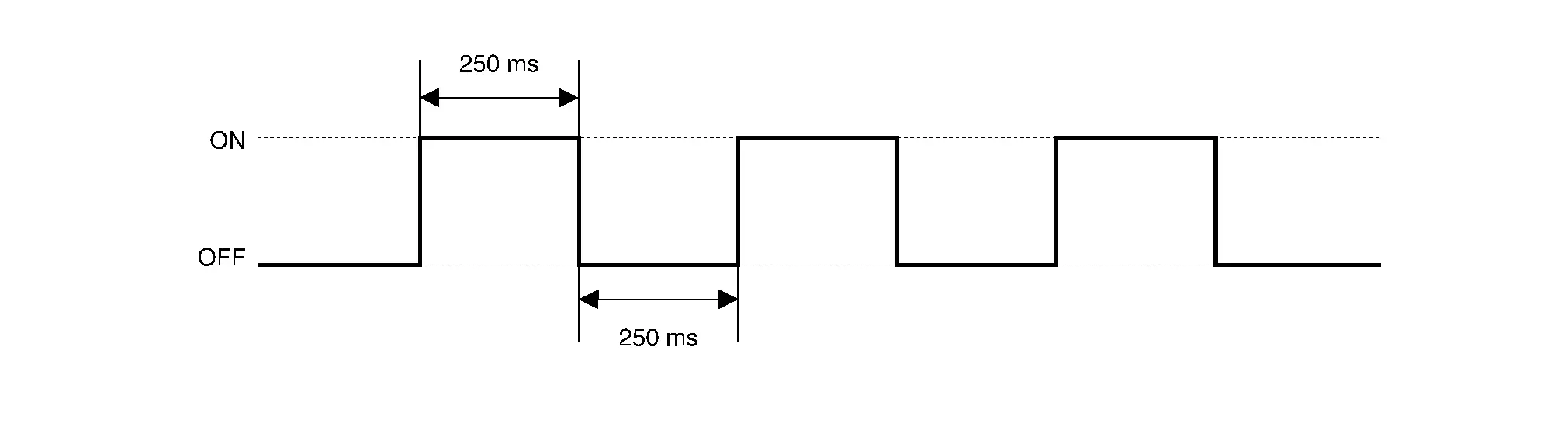
Other materials:
Turning the AEB with Pedestrian Detection system ON/OFF
AEB system OFF warning light (on the meter panel)
Vehicle information display
Steering-wheel-mounted controls (left side)
Follow the steps below to switch the AEB with Pedestrian Detection system on or off in your Nissan Rogue.
1. Press the
button until ŌĆ£SettingsŌĆØ appears in the vehicle ...
System
I-Fcw
System Description
SYSTEM DIAGRAM Component Description
ABS actuator and electric unit (control unit)
ABS Actuator and Electric Unit (Control Unit)
Combination meter (FULL TFT METER)
Combination Meter
Combination meter (7 INCH INFORMATION DISPLAY)
Combination Meter
...
Diagnosis System (av Control Unit)
Nissanconnect with 8" Color Display
On Board Diagnosis Function
The AV control unit on board diagnosis performs the functions listed in the table below:DESCRIPTION Mode Description
Self Diagnosis
Audio system diagnosis.
Diagnoses the connections across system components.
...