Nissan Rogue (T33) 2021-Present Service Manual: Structure and Operation
Positive Crankcase Ventilation

In a supercharged engine, since the negative pressure in the intake manifold is insufficient, the blow-by gas in the crankcase cannot be sufficiently ventilated with a usual PCV valve only.
The negative pressure generated even in the supercharging range can be used to compensate the range where the PCV valve does not work by closing the admission valve which is adopted between the airflow sensor and the turbocharger.

Ventilation gas flow when not supercharging
Blow- by gas flows from the PCV valve to the intake manifold, but it does not flow from the one way valve to the supercharging ventilation piping.
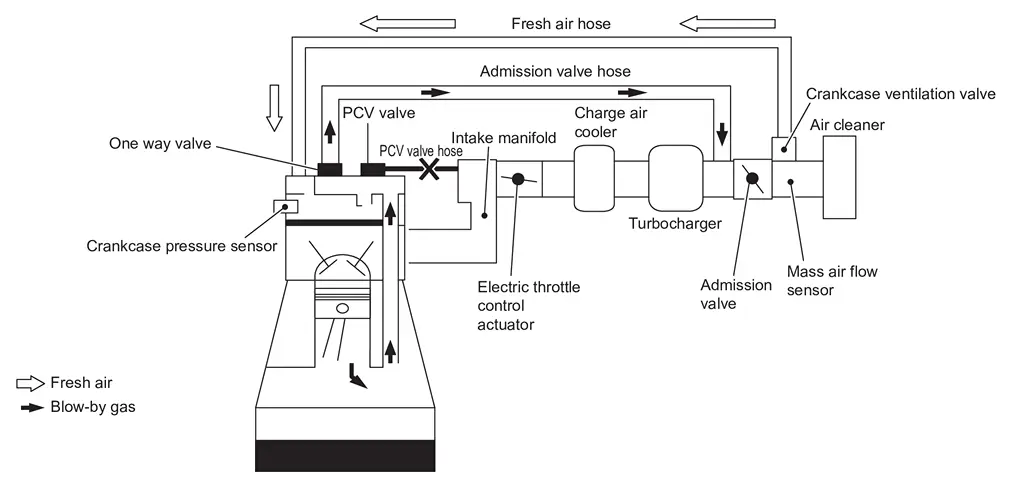
Ventilation gas flow when not supercharging
Blow-by gas does not flow from the PCV valve to the intake manifold due to the positive pressure of the intake manifold.
It returns to the intake manifold through the "supercharging ventilation pipe" due to the negative pressure of the admission valve.

Crankcase ventilation valve is operated to leak detection of blow-by gas .
Crankcase pressure sensor measure inside pressure of crankcase under the condition that fresh air flow is shut off and detect leak.
On Board Refueling Vapor Recovery (ORVR)
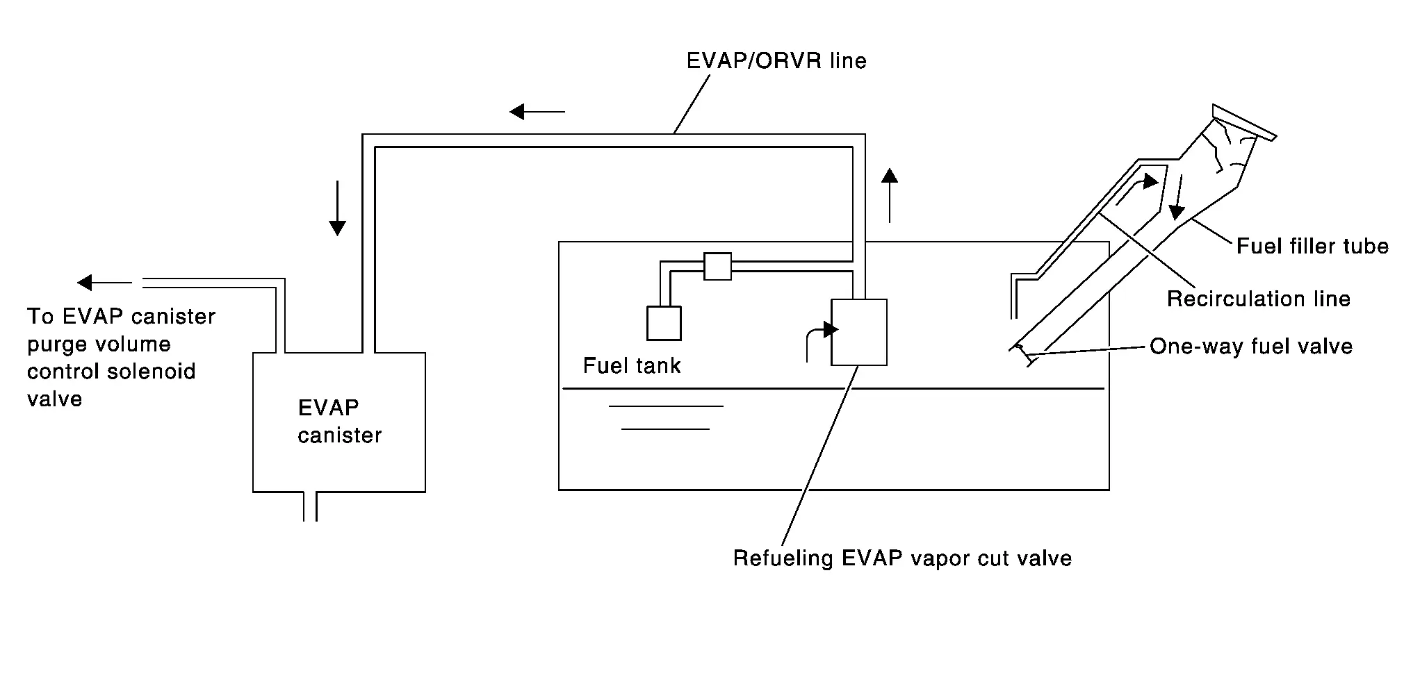
From the beginning of refueling, the air and vapor inside the fuel tank go through refueling EVAP vapor cut valve and EVAP/ORVR line to the EVAP canister. The vapor is absorbed by the EVAP canister and the air is released to the atmosphere.
When the refueling has reached the full level of the fuel tank, the refueling EVAP vapor cut valve is closed and refueling is stopped because of auto shut-off. The vapor which was absorbed by the EVAP canister is purged during driving.
WARNING:
When conducting inspections below, be sure to observe the following:
-
Put a “CAUTION: FLAMMABLE” sign in workshop.
-
Do not smoke while servicing fuel system. Keep open flames and sparks away from work area.
-
Be sure to furnish the workshop with a CO2 fire extinguisher.
CAUTION:
-
Before removing fuel line parts, carry out the following procedures:
-
Put drained fuel in an explosion-proof container and put lid on securely.
-
Release fuel pressure from fuel line. Refer to Work Procedure.
-
Disconnect battery ground cable.
-
-
Always replace O-ring when the fuel gauge retainer is removed.
-
Do not kink or twist hose and tube when they are installed.
-
Do not tighten hose and clamps excessively to avoid damaging hoses.
-
After installation, run engine and check for fuel leaks at connection.
-
Do not attempt to top off the fuel tank after the fuel pump nozzle shuts off automatically.
Continued refueling may cause fuel overflow, resulting in fuel spray and possibly a fire.
Other materials:
Dtc/circuit Diagnosis. B2046-42 Eeprom
DTC Description
DTC DETECTION LOGIC DTC No.
CONSULT screen items
(Trouble diagnosis content) DTC Detection Condition
B2046-42
EEPROM
(Electrically Erasable Programmable Read-Only Memory)
Diagnosis condition
Ignition switch ON
Signal (terminal)
—
Threshold
EEPROM ...
Steering Switch Signal a Circuit
Component Function Check
CHECK COMBINATION METER INPUT SIGNAL
CONSULT
Ignition switch ON.
Select “Steering switch input” in “Data monitor” mode of “M&A”.
Check that the function operates normally according to the following conditions:
Condition Value
CONTRO ...
Nissanconnect. Preparation. Preparation
Preparation
Commercial Service Tools
Tool Description
Power tool
Loosening screws
Always Replace With New Parts
Always Replace With New PartsNever Reuse These PartsPart CodeFor additional information:
Washer
-
ROOF ANTENNA EXPLODED VIEW
...