Nissan Rogue (T33) 2021-Present Service Manual: Component Parts
Engine Control System
Component Parts Location
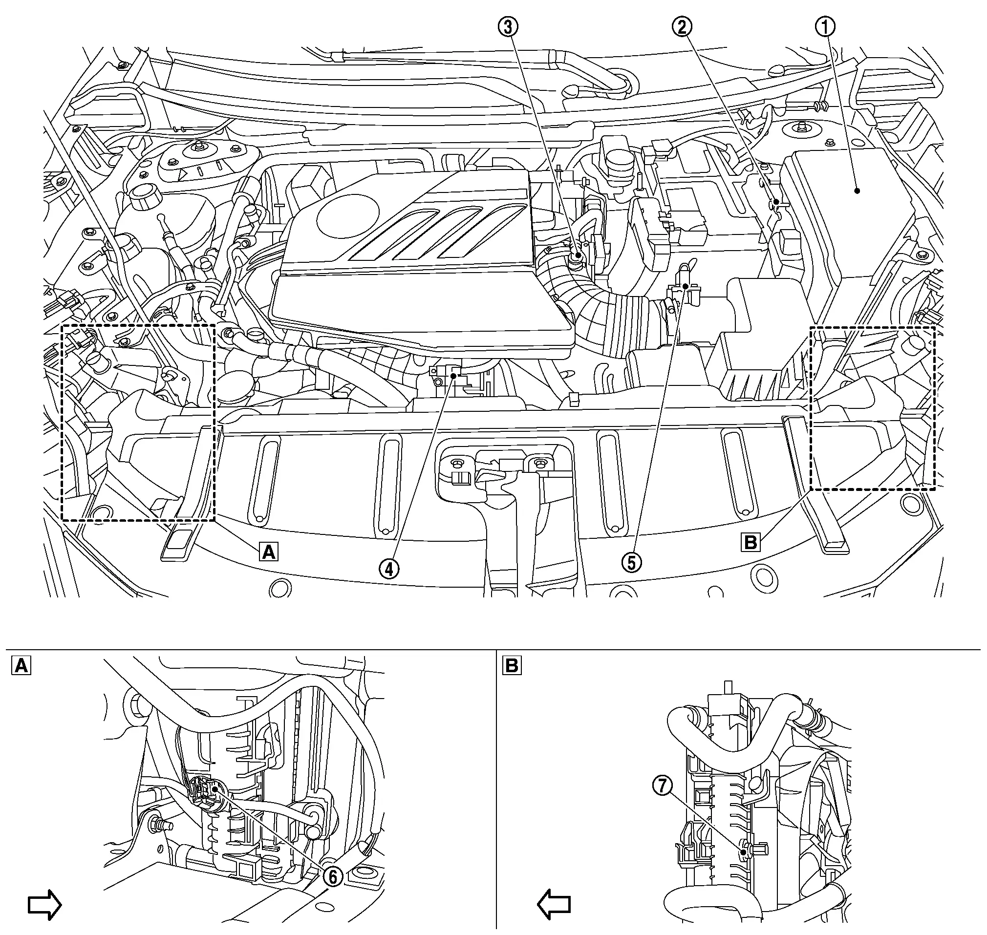
ENGINE ROOM COMPARTMENT
 |
Right front of Nissan Ariya vehicle |  |
Left front of vehicle | ||
 |
Nissan Ariya Vehicle front |
 |
IPDM E/R |  |
ECM |  |
Admission valve |
 |
Turbocharger boost sensor (With intake air temperature sensor 2) |
 |
Mass air flow sensor |  |
Refrigerant pressure sensor |
 |
Engine coolant temperature sensor 2 |
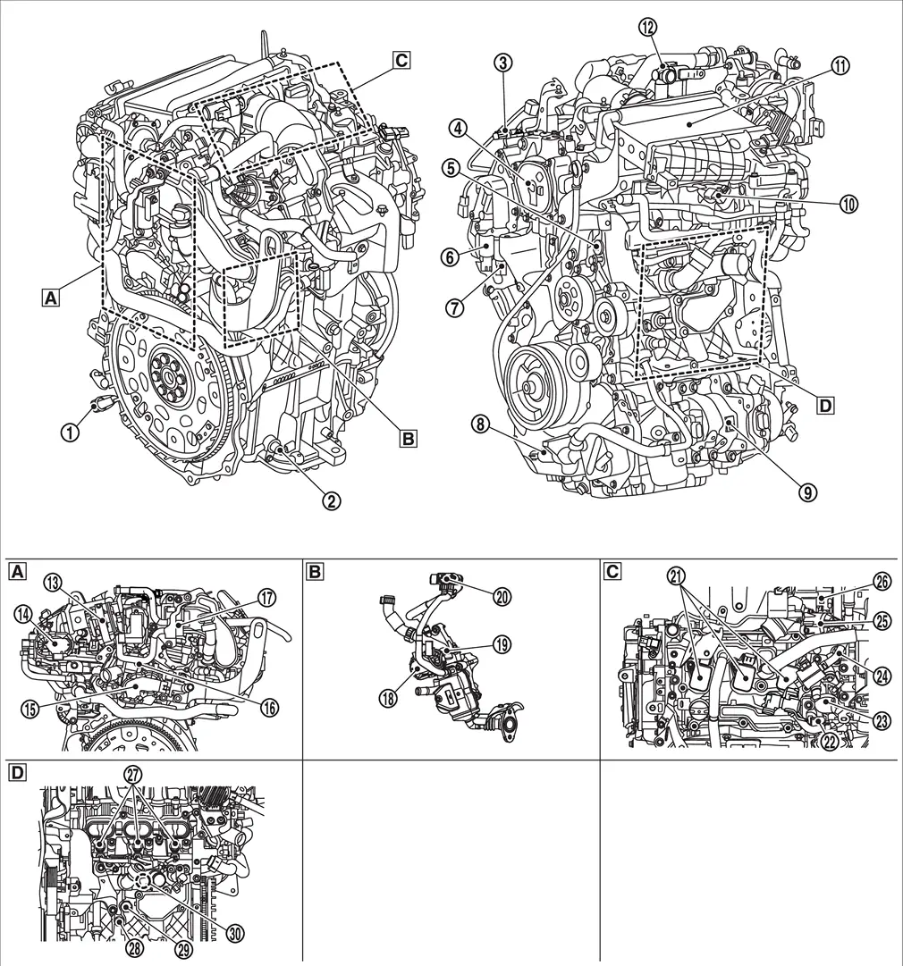
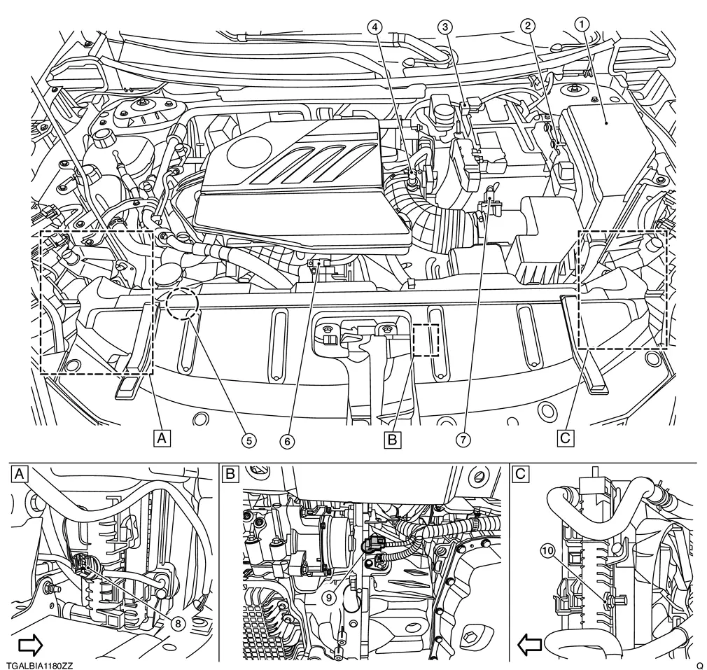
ENGINE COMPARTMENT
|
Rear view of the engine | |
Side view of the engine |  |
Top view of the engine |
 |
Side view of the engine (view with intake manifold is removed) |
|
Crankshaft position sensor | |
Engine oil level sensor | |
Crankcase Pressure Sensor |
|
Electric intake valve timing control actuator | |
Fuel rail pressure sensor | |
Exhaust valve timing control solenoid valve |
|
Exhaust valve timing intermediate lock control solenoid valve |  |
Engine oil pressure control solenoid valve |  |
VCR actuator |
 |
Manifold absolute pressure (MAP) sensor |  |
Water charge air cooler |  |
Crankcase Ventilation Valve |
 |
EVAP canister electric purge pump |  |
Electric throttle control actuator |  |
Multi-way control valve |
 |
Engine coolant temperature sensor 1 |  |
EVAP canister purge volume control solenoid valve |  |
EGR volume control valve |
 |
EGR temperature sensor |  |
EGR differential pressure sensor |  |
Ignition coil (with power transistor) |
 |
Intake camshaft position sensor |  |
High pressure fuel pump |  |
Exhaust camshaft position sensor |
 |
Electric wastegate control actuator |  |
Turbocharger bypass control valve |  |
Fuel injector |
 |
Engine oil temperature sensor |  |
Engine oil pressure sensor |  |
Knock sensor |
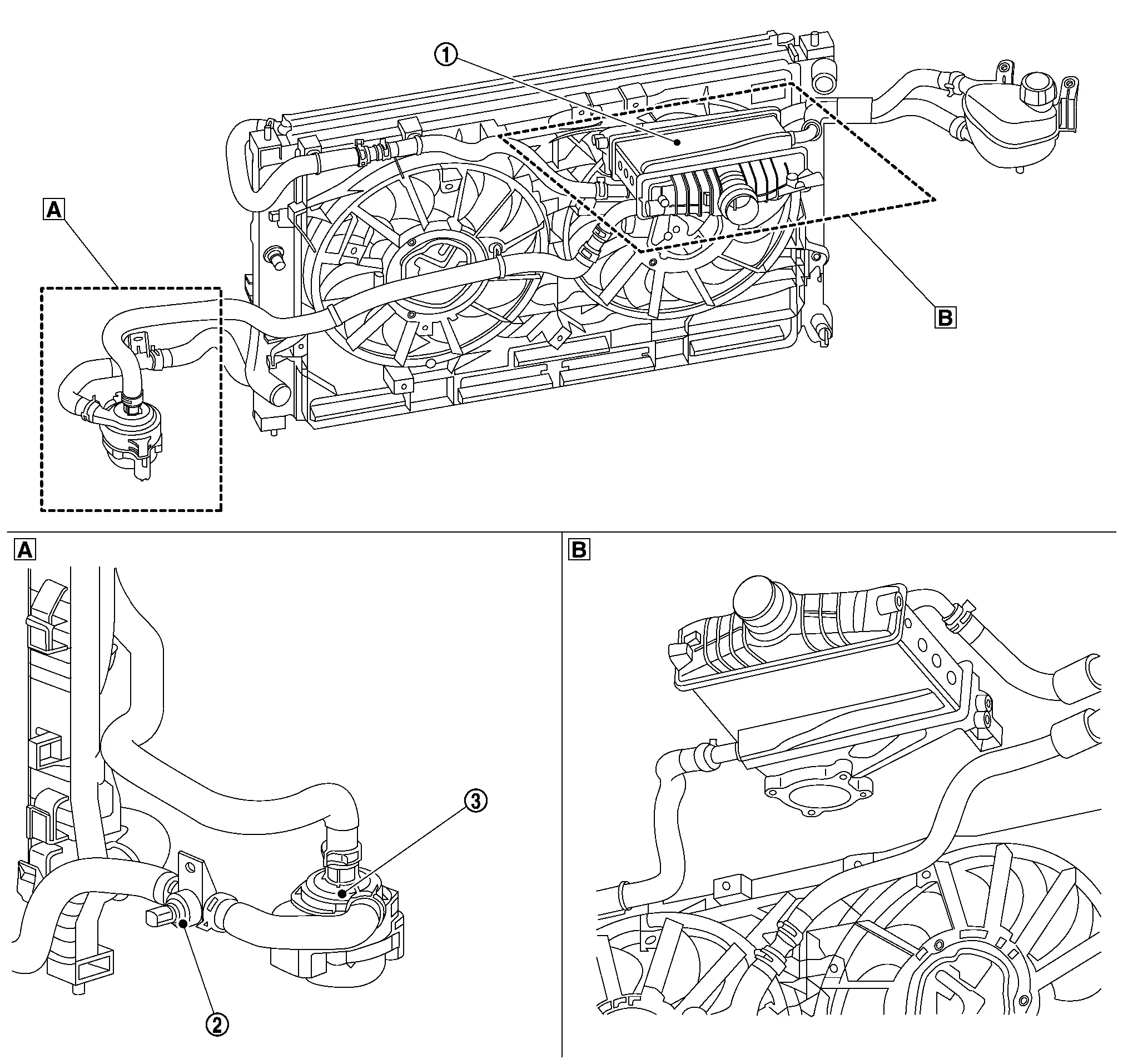
CHARGE AIR COOLER COOLING SYSTEM COMPONENT
|
Left front of Nissan Ariya vehicle | |
Top view of the engine |
|
Charge air cooler | |
Charge air cooler coolant temperature sensor | |
Charge air cooler electric water pump |
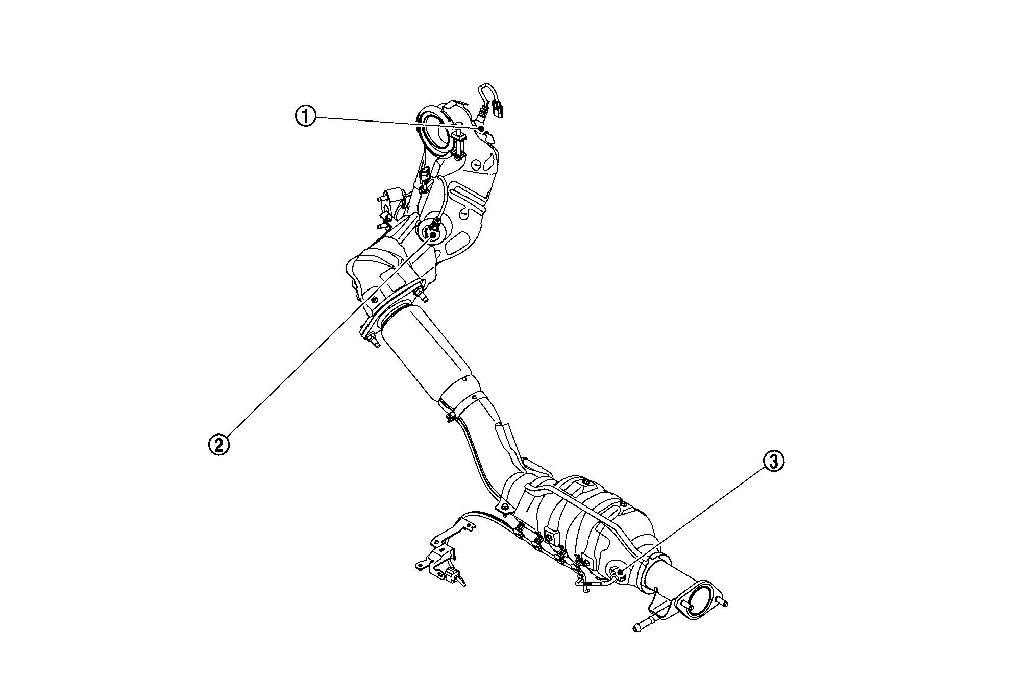
EXHAUST COMPARTMENT
|
Air fuel ratio (A/F) sensor 1 | |
Heated oxygen sensor 2 | |
Exhaust gas temperature sensor |
BODY COMPARTMENT
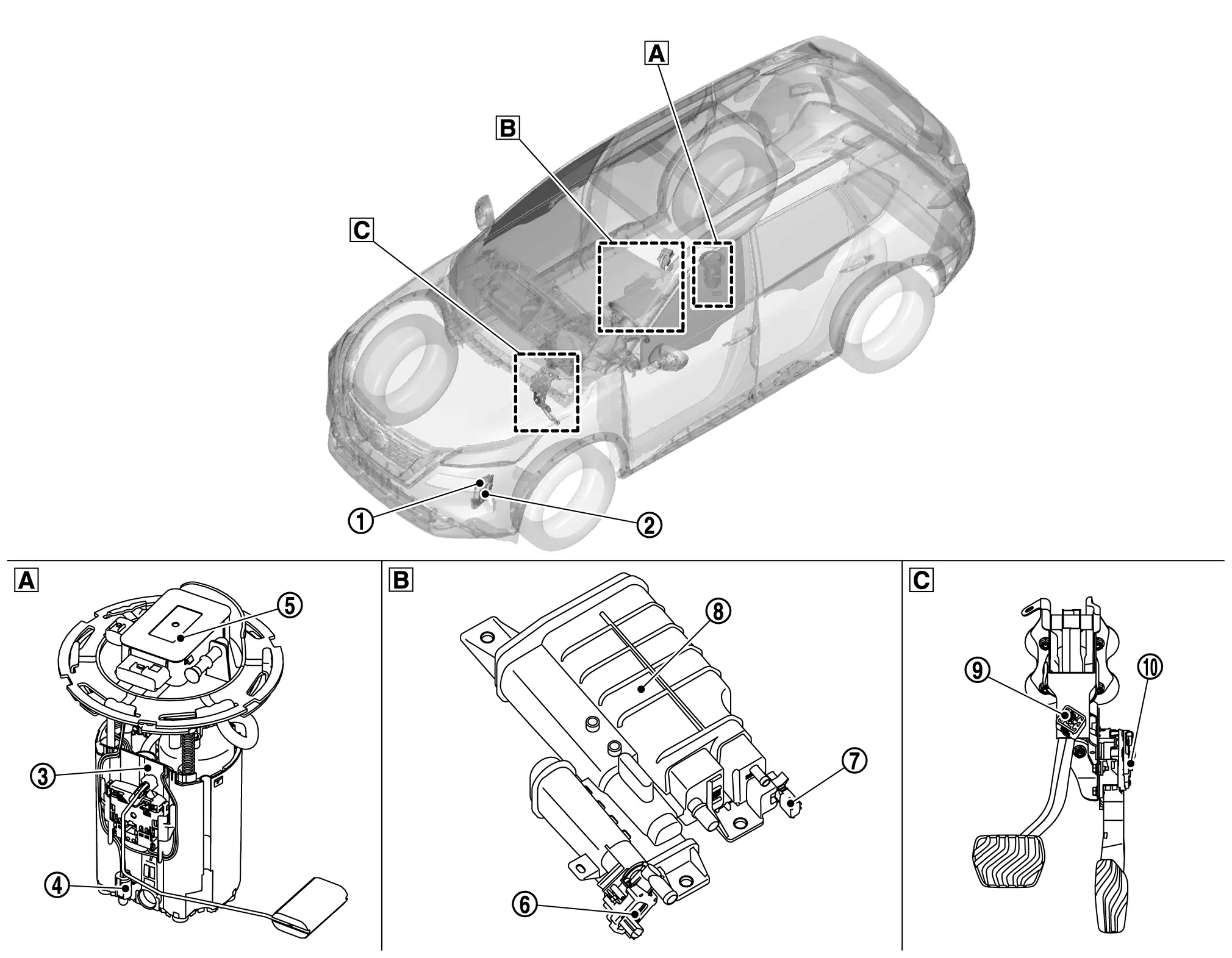
|
Inside fuel tank area | |
Front of fuel tank area | |
Accelerator pedal area |
|
Electric intake valve timing control module | |
VCR control module | |
Fuel pump |
|
Fuel level sensor unit | |
FPCM (Fuel pump control module) | |
EVAP canister vent control valve |
|
EVAP control system pressure sensor | |
EVAP canister | |
Stop lamp switch |
|
Accelerator pedal position sensor |
Stop/start System
Component Parts Location
Engine Room Component
|
Right front of Nissan Ariya vehicle | |
Lower center front of Nissan Ariya vehicle | |
Left front of Nissan Ariya vehicle |
|
IPDM E/R | |
ECM | |
12V battery current sensor |
|
Admission valve | |
Sub-starter & generator | |
Turbocharger boost sensor (With intake air temperature sensor 2) |
|
Mass air flow sensor | |
Refrigerant pressure sensor | |
Crankshaft position sensor 2 |
|
Engine coolant temperature sensor 2 |
Body Compartment
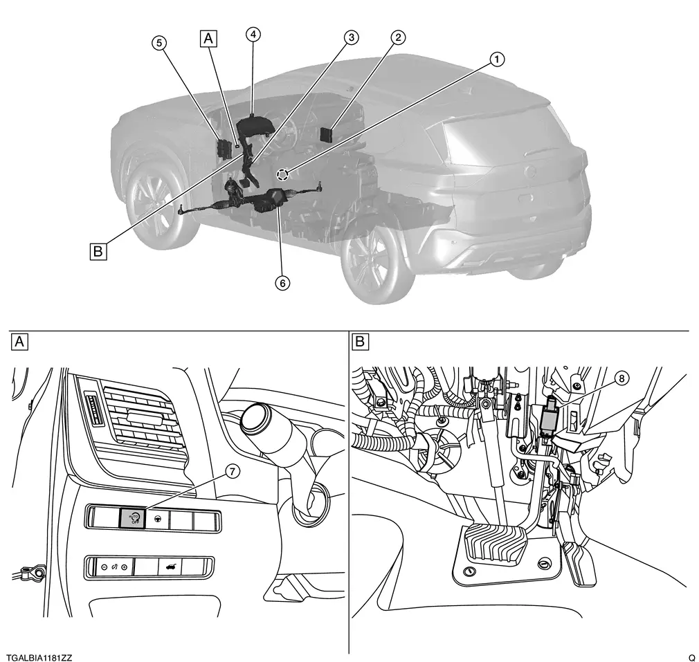
|
Left side of steering column | |
Pedal periphery |
|
Door switch (driver side) | |
A/C auto amp. | |
Accelerator pedal position sensor |
|
Combination meter | |
BCM | |
Power steering control module |
|
Stop/start OFF switch | |
Stop lamp switch |
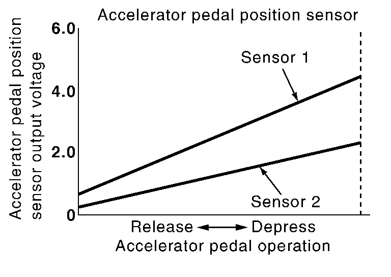
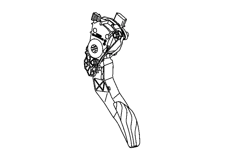
Accelerator Pedal Position Sensor
FUNCTIONS WITHIN THE SYSTEM
-
Accelerator pedal position sensor detects the opening and closing speed of the accelerator pedal and feed the voltage signals to the ECM. The ECM judges the current opening angle of the accelerator pedal from this signal and controls the throttle control motor based on this signal.
-
Idle position of the accelerator pedal is determined by the ECM receiving the signal from the accelerator pedal position sensor. The ECM uses this signal for the engine operation such as fuel cut.
INDIVIDUAL FUNCTION WITHIN THE SYSTEM
Detects the amount that the accelerator pedal is depressed.
INDIVIDUAL OPERATION
The accelerator pedal position sensor has two sensors. These sensors are a kind of potentiometers which transform the accelerator pedal position into output voltage, and emit the voltage signal to the ECM.
COMPONENT PARTS LOCATION
The accelerator pedal position sensor is installed on the upper end of the accelerator pedal assembly.
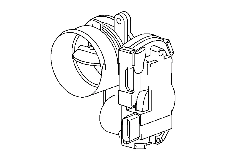
Admission Valve
FUNCTIONS WITHIN THE SYSTEM
The ECM transmits the control signal to the admission valve and controls the throttle position according to the driving conditions.
INDIVIDUAL FUNCTION WITHIN THE SYSTEM
The admission valve consists of admission valve, admission valve control motor and admission valve position sensor.
INDIVIDUAL OPERATION
Admission Valve Motor
The admission valve motor is operated by the ECM and it opens and closes the throttle valve.
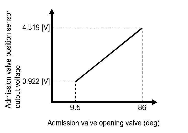
Admission Valve Position Sensor
These sensors are a kind of potentiometers which transform the admission valve position into output voltage, and emit the voltage signal to the ECM. In addition, these sensors detect the opening and closing speed of the admission valve and feed the voltage signals to the ECM. The ECM judges the current opening angle of the admission valve from these signals.
COMPONENT PARTS LOCATION
The admission valve is installed between the air cleaner and the turbocharger.
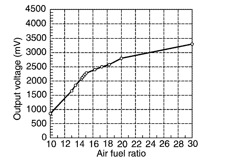
Air Fuel Ratio (A/F) Sensor 1
FUNCTIONS WITHIN THE SYSTEM
ECM judges the state of air fuel ratio with this signal, and precisely controls air fuel ratio to match the stoichiometric ratio. Also, the sensor is equipped with heater for maintaining the activated state.
INDIVIDUAL FUNCTION WITHIN THE SYSTEM
A/F Sensor 1
The A/F sensor 1 transmits the signal of detected oxygen concentration in the exhaust gas to ECM.
A/F Sensor 1 Heater
The A/F sensor 1 heater activates A/F sensor 1.
INDIVIDUAL OPERATION
A/F Sensor 1
While O2 sensor changes output voltage by ON/OFF (rich/lean) mode within a narrow range of the stoichiometric ratio, the A/F sensor changes output voltage between 0 - 4 V for a wide range of air fuel ratio.
A/F Sensor 1 Heater
The ECM performs ON/OFF duty control of the A/F sensor 1 heater corresponding to condition to keep the temperature of A/F sensor 1 element within the specified range.
COMPONENT PARTS LOCATION
The A/F sensor 1 is installed on the exhaust manifold.
ASCD Steering Switch
FUNCTIONS WITHIN THE SYSTEM
The ECM controls the ASCD based on the signal that is transmitted from the ACSD steering switch.
INDIVIDUAL FUNCTION WITHIN THE SYSTEM
The ACSD steering switch transmits the signals of the switches operated by the driver to the ECM.
INDIVIDUAL OPERATION
Each switch circuit has a resistor with a different resistance connected in series.
The ECM reads the voltage values that are transmitted from each switch and split by the resistors, and detects which button is operated. The ECM reads the voltage values that are transmitted from each switch and split by the resistors, and detects which button is operated.
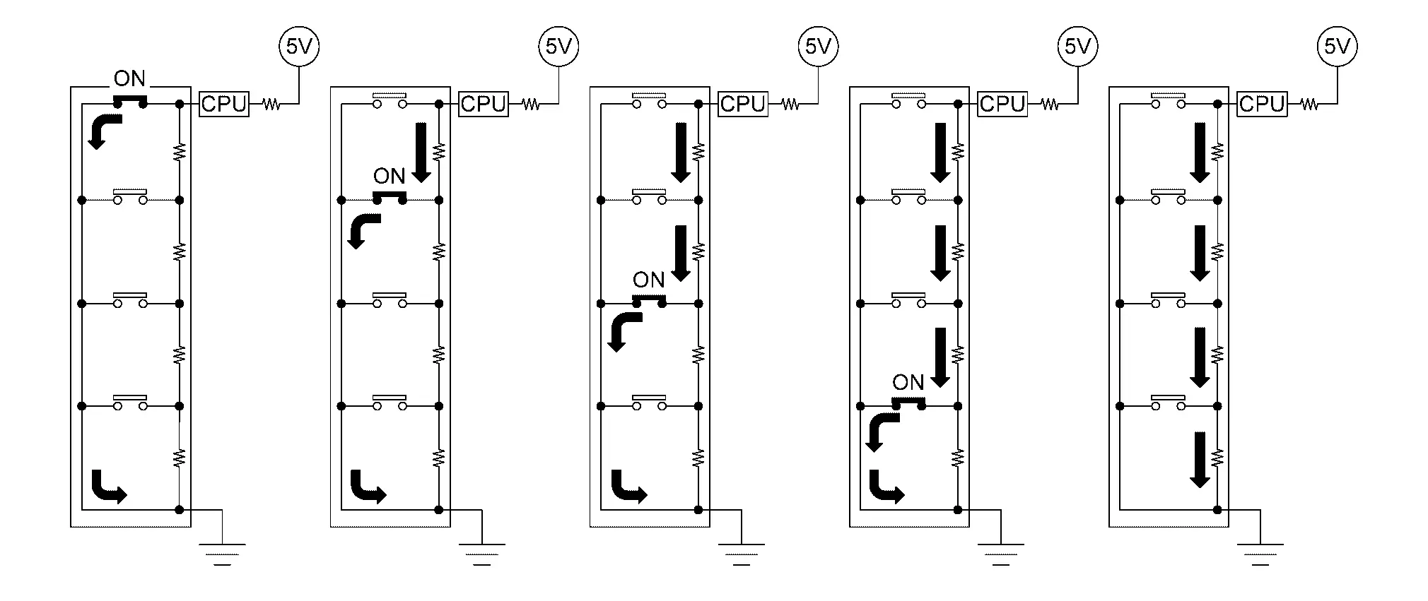
COMPONENT PARTS LOCATION
ASCD steering switch is installed on steering wheel.
Charge Air Cooler Coolant Temperature Sensor
FUNCTIONS WITHIN THE SYSTEM
ECM receives the charge air cooler coolant temperature signal from the charge air cooler coolant temperature sensor and performs various control.
INDIVIDUAL FUNCTION WITHIN THE SYSTEM
The charge air cooler coolant temperature sensor is used to detect the charge air cooler coolant temperature.
INDIVIDUAL OPERATION
The charge air cooler coolant temperature sensor uses a thermistor which is sensitive to the change in temperature. The electrical resistance of the thermistor decreases as temperature increases.
| Temperature [┬░C (┬░F)] | Voltage* (V) | Resistance (kŌä”) |
|---|---|---|
| ŌłÆ10 (14) | 4.4 | 7.0 - 11.4 |
| 20 (68) | 3.5 | 2.10 - 2.90 |
| 50 (122) | 2.2 | 0.68 - 1.00 |
| 90 (194) | 0.9 | 0.236 - 0.260 |
*: These data are reference values and are measured between ECM terminals and sensor ground.
COMPONENT PARTS LOCATION
The charge air cooler coolant temperature sensor is mounted in the middle of the charge air cooler cooling electric water pump and sub radiator.
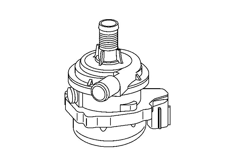
Charge Air Cooler Cooling Electric Water Pump
FUNCTIONS WITHIN THE SYSTEM
The ECM receives a signal such as a charge air cooler coolant temperature sensor, activates the charge air cooler cooling electric water pump, and circulates the charge air cooler coolant.
INDIVIDUAL FUNCTION WITHIN THE SYSTEM
The charge air cooler cooling electric water pump is a pump that changes the flow rate of charge air cooler coolant.
INDIVIDUAL OPERATION
The charge air cooler cooling electric water pump is activated according to a drive duty signal transmitted from ECM and circulates charge air cooler coolant.
COMPONENT PARTS LOCATION
The charge air cooler electric water pump is mounted in the middle of the charge air cooler and sub radiator.
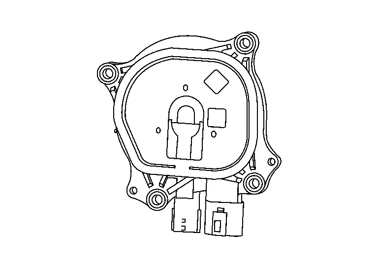
Cooling Fan
FUNCTIONS WITHIN THE SYSTEM
Cooling fan motor receives cooling fan motor operating voltage from cooling fan control module. The revolution speed of cooling fan motor is controlled by duty cycle of the voltage.
INDIVIDUAL FUNCTION WITHIN THE SYSTEM
The cooling fan is composed of the cooling fan motor which drives the cooling fan and the cooling fan control module which supply power.
INDIVIDUAL OPERATION
Cooling Fan Control Module
Cooling fan control module receives ON/OFF pulse duty signal from IPDM E/R. Corresponding to this ON/OFF pulse duty signal, cooling fan control module sends cooling fan motor operating voltage to cooling fan motor. The revolution speed of cooling fan motor is controlled by duty cycle of the voltage.
COMPONENT PARTS LOCATION
The cooling fan motor and cooling fan control module are installed on the cooling fan shroud.
Crankcase Pressure Sensor
FUNCTIONS WITHIN THE SYSTEM
ECM detects malfunction of crankcase ventilation system by operating crankcase ventilation valve and control inside pressure of crankcase.
INDIVIDUAL FUNCTION WITHIN THE SYSTEM
Crankcase pressure sensor outputs pressure difference between the internal pressure of engine crankcase and the ambient pressure.
INDIVIDUAL OPERATION
Crankcase pressure sensor use piezoelectric element on its diaphragm and output voltage changes by changing of relative pressure inside and outside of engine.
COMPONENT PARTS LOCATION
The crankcase pressure sensor is installed to the upper of front cover.
Crankcase Ventilation Valve
FUNCTIONS WITHIN THE SYSTEM
ECM detects malfunction of crankcase ventilation system by operating crankcase ventilation valve and control inside pressure of crankcase.
INDIVIDUAL FUNCTION WITHIN THE SYSTEM
Crankcase ventilation valve opens and closes air cleaner side of fresh air passage between rocker cover and air duct.
INDIVIDUAL OPERATION
Crankcase ventilation valve is activated by ON/OFF signals from ECM.
ON signal from ECM close the valve and fresh air flow is shut off.
COMPONENT PARTS LOCATION
Crankcase ventilation valve is installed at the air duct.
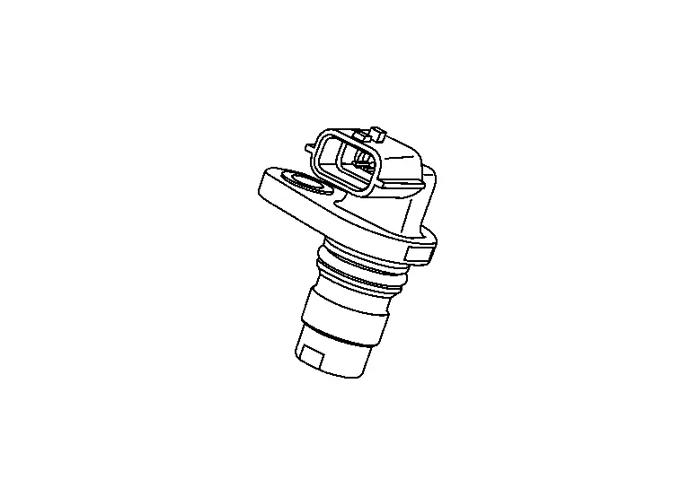
Crankshaft Position Sensor
FUNCTIONS WITHIN THE SYSTEM
The ECM judges the engine speed based on the crankshaft position signal that is input into it.
INDIVIDUAL FUNCTION WITHIN THE SYSTEM
The ECM inputs the voltage change caused by the change in magnetic field generated close to the crankshaft position sensor as signal voltage.
INDIVIDUAL OPERATION
Crankshaft position sensor consists of a permanent magnet and Hall IC. When the engine is running, the high and low parts of the teeth cause the gap with the sensor to change. The changing gap causes the magnetic field near the sensor to change. Due to the changing magnetic field, the voltage from the sensor changes.
COMPONENT PARTS LOCATION
Crankshaft position sensor (POS) is installed on the transmission housing.
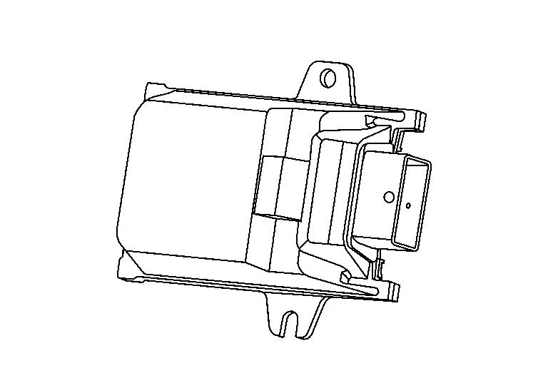
ECM
FUNCTIONS WITHIN THE SYSTEM
ECM controls the engine system based on signals from the various control modules and sensors.
INDIVIDUAL FUNCTION WITHIN THE SYSTEM
-
The ECM consists of the microcomputer and input/output connectors for signal and power supply.
-
When the ignition switch is turned OFF, power is supplied continuously from the battery for maintaining the DTC and memory functions.
-
The ECM includes a self-diagnosis function for simplifying trouble diagnosis.
-
For supporting DIG (Direct Injection Gasoline), the ECM includes a high-voltage injector driver.
-
The ECM contains an atmospheric pressure sensor.
INDIVIDUAL OPERATION
The ECM controls a variety of engine systems. Refer to System Description.
COMPONENT PARTS LOCATION
The ECM is installed on the underside of the vehicle front side of the left front fender protector.

EGR Differential Pressure Sensor
FUNCTIONS WITHIN THE SYSTEM
EGR differential pressure sensor is connected to EGR valve with pressure tube.
INDIVIDUAL FUNCTION WITHIN THE SYSTEM
EGR differential pressure sensor measures the differential pressure between upstream and downstream of the EGR valve. It converts into a voltage signal.
INDIVIDUAL OPERATION
ECM receives the signal via engine communication and estimates the EGR valve opening ratio or EGR valve position.
COMPONENT PARTS LOCATION
The EGR differential pressure sensor is mounted on the exhaust side of the cylinder head.
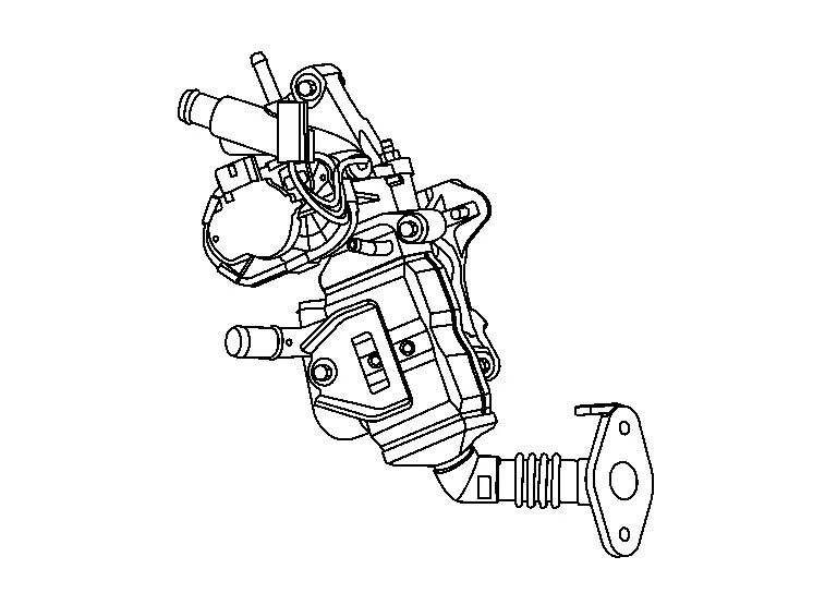
EGR Volume Control Valve
FUNCTIONS WITHIN THE SYSTEM
The EGR volume control valve utilizes a step motor to control the EGR flow rate from the exhaust manifold, and controls the valve opening depending on the driving condition in accordance with the command from the ECM.
INDIVIDUAL FUNCTION WITHIN THE SYSTEM
The EGR volume control valve controls the valve opening by turning the step motor on and off, and controls the EGR flow rate.
INDIVIDUAL OPERATION
EGR VOLUME CONTROL VALVE
The step motor of the EGR volume control valve consists of four coils facing each other. When the system 1 is turned on by the output signal from the ECM, the other system 1 of the same circuit is turned off. The valve is opened by changing the order in which the coils are energized, and the valve is closed by energizing in the reverse order. The valve is held in that position by energizing some of the four coils.
EGR VOLUME CONTROL VALVE POSITION SENSOR
The EGR volume control valve position sensor is built in the EGR volume control valve and uses a permanent magnet and a semiconductor device. This sensor measures valve shaft movements and transmits a voltage signal to ECM. Based on this signal, ECM judges the valve opening angle as of then and controls the motor to achieve opening angle appropriate to the driving conditions.
EGR TEMPERATURE SENSOR
The EGR temperature sensor detects temperature changes in the EGR passage. When the cooling efficiency of EGR cooler is extremely low, exhaust gas is not cooled than expected, and the temperature in the passage changes. The EGR temperature sensor is a thermistor that modifies a voltage signal transmitted from the ECM. This modified signal then returns to the ECM as an input signal. When the temperature increases, EGR temperature sensor resistance decreases.
COMPONENT PARTS LOCATION
The EGR control valve is mounted on the exhaust side of the cylinder head.
Electric Intake Valve Timing Control Actuator
FUNCTIONS WITHIN THE SYSTEM
The electric intake valve timing control actuator operates the electric intake valve timing control motor based on the signal from the electric intake valve timing control module, and it advances or retards the intake valve timing according to the conditions. It also transmits the motor position and motor speed to the electric intake valve timing control module based on the electric intake valve timing control position sensor.
INDIVIDUAL FUNCTION WITHIN THE SYSTEM
It is composed of the electric intake valve timing control motor and electric intake valve timing control actuator (located inside the electric intake valve timing control position sensor).
INDIVIDUAL OPERATION
The electric intake valve timing control motor rotates in the same direction as the intake camshaft, and the difference in rotation controls timing advancement, holding, and retardation.
COMPONENT PARTS LOCATION
The electric intake valve timing control actuator (located inside the electric intake valve timing control position sensor) is installed on the engine front side of the intake camshaft.
The electric intake valve timing control motor is installed inside the cam sprocket (INT).
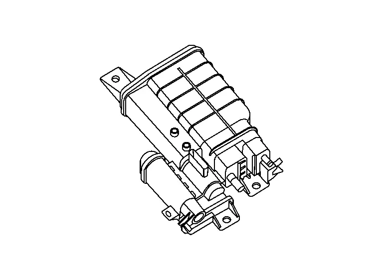
Electric Intake Valve Timing Control Module
FUNCTIONS WITHIN THE SYSTEM
The electric intake valve timing control module controls the electric intake valve timing control actuator based on the signals from the ECM and the electric intake valve timing control position sensor. The target intake valve timing angle is also corrected by the signal transmitted from the ECM via CAN communication.
INDIVIDUAL FUNCTION WITHIN THE SYSTEM
The electric intake valve timing control module controls the electric intake valve timing control actuator according to the signal from the ECM, and changes the intake valve open/close timing. It also has a diagnosis function and transmits a malfunction detection signal to the ECM via CAN communication.
INDIVIDUAL OPERATION
The electric intake valve timing control module controls the electric intake valve timing control actuator, and if it detects a malfunction, it transmits a malfunction detection signal to the ECM via CAN communication.
COMPONENT PARTS LOCATION
The electric intake valve timing control module is installed to the engine room left side.
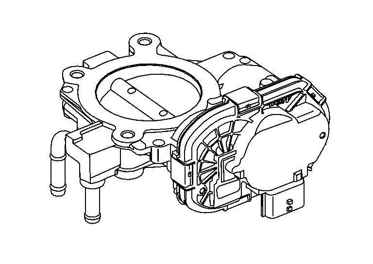
Electric Throttle Control Actuator
FUNCTIONS WITHIN THE SYSTEM
The ECM transmits the control signal to the electronically controlled throttle and controls the throttle position according to the driving conditions.
INDIVIDUAL FUNCTION WITHIN THE SYSTEM
The electric throttle control actuator consists of throttle body, throttle valve, throttle control motor and throttle position sensor.
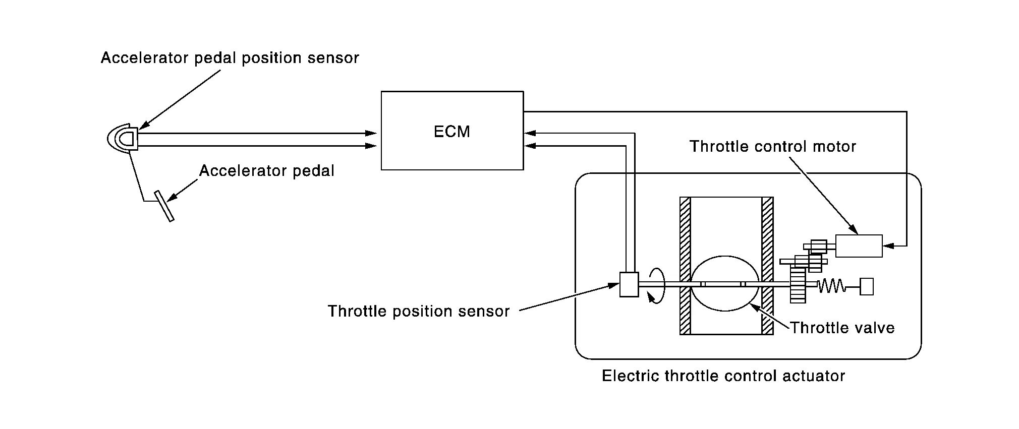
INDIVIDUAL OPERATION
Throttle Motor
The throttle control motor is operated by the ECM and it opens and closes the throttle valve.
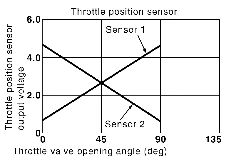
Throttle Position Sensor
The throttle position sensor has two sensors. These sensors are a kind of potentiometers which transform the throttle valve position into output voltage, and emit the voltage signal to the ECM. In addition, these sensors detect the opening and closing speed of the throttle valve and feed the voltage signals to the ECM. The ECM judges the current opening angle of the throttle valve from these signals.
COMPONENT PARTS LOCATION
The electric throttle valve actuator is installed beside the intake manifold collector.
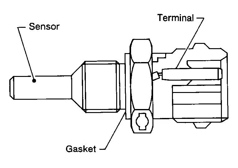
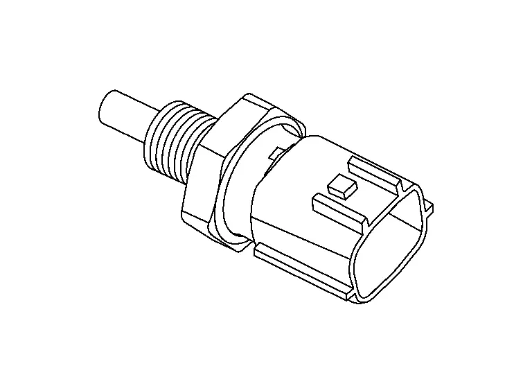
Engine Coolant Temperature Sensor
FUNCTIONS WITHIN THE SYSTEM
ECM receives the engine coolant temperature signal from the engine coolant temperature sensor and performs various control.
INDIVIDUAL FUNCTION WITHIN THE SYSTEM
The engine coolant temperature sensor is used to detect the engine coolant temperature.
INDIVIDUAL OPERATION
The engine coolant temperature sensor uses a thermistor which is sensitive to the change in temperature. The electrical resistance of the thermistor decreases as temperature increases.
| Temperature [┬░C (┬░F)] | Voltage* (V) | Resistance (kŌä”) |
|---|---|---|
| ŌłÆ10 (14) | 4.18 ŌĆō 4.40 | 7.0 ŌĆō 11.4 |
| 20 (68) | 3.39 ŌĆō 3.50 | 2.37 ŌĆō 2.63 |
| 50 (122) | 1.98 ŌĆō 2.44 | 0.68 ŌĆō 1.00 |
| 90 (194) | 0.94 ŌĆō 1.03 | 0.236 ŌĆō 0.260 |
*: These data are reference values and are measured between ECM terminals.
COMPONENT PARTS LOCATION
Engine Coolant Temperature Sensor 1
The engine coolant temperature sensor is installed to the multi-way control valve.
Engine Coolant Temperature Sensor 2
The engine coolant temperature sensor is installed to the radiator.
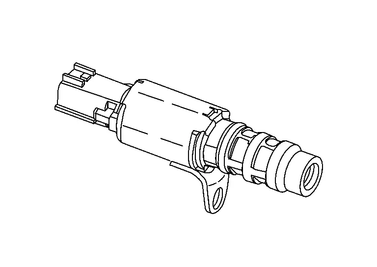
Engine Oil Pressure Control Solenoid Valve
The engine oil pressure control solenoid valve performs the variable hydraulic control (low oil pressure control and high oil pressure control) according to oil temperature and engine load.
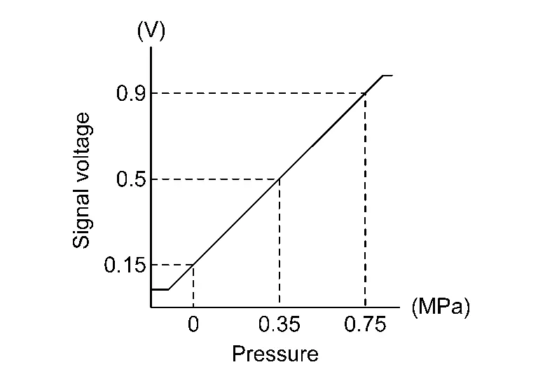
Engine Oil Pressure Sensor
FUNCTIONS WITHIN THE SYSTEM
When the ECM detects low engine oil pressure, it turns ON the oil pressure warning lamp on the combination meter.
INDIVIDUAL FUNCTION WITHIN THE SYTEM
Engine oil pressure (EOP) sensor is detects engine oil pressure and transmits a voltage signal to the ECM.
INDIVIDUAL OPERATION
When the engine oil pressure rises, the signal voltage increases.
COMPONENT PARTS LOCATION
The engine oil pressure sensor is installed to cylinder block.
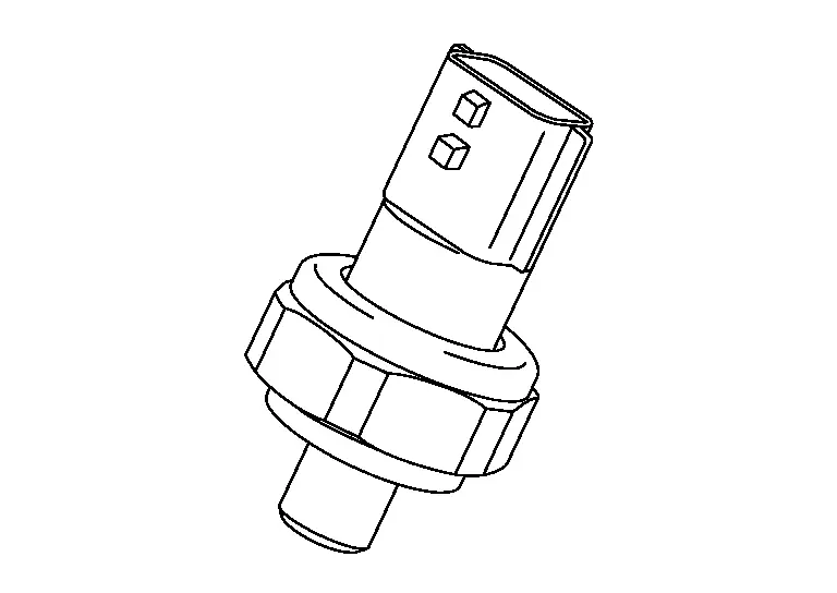
Engine Oil Temperature Sensor
FUNCTIONS WITHIN THE SYSTEM
The engine oil temperature signal that is received from the oil temperature signal is used by the ECM for valve timing control.
INDIVIDUAL FUNCTION WITHIN THE SYSTEM
The engine oil temperature sensor detects the engine oil temperature, converts it to an output voltage, and transmits a signal to the ECM.
INDIVIDUAL OPERATION
The engine oil temperature sensor uses a thermistor which is sensitive to the change in temperature. The electrical resistance of the thermistor decreases as temperature increases.
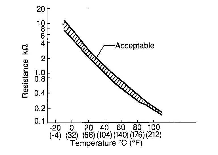
| Temperature [┬░C (┬░F)] | Voltage* (V) | Resistance (kŌä”) |
|---|---|---|
| ŌĆō10 (14) | 4.18 - 4.40 | 7.0 - 11.4 |
| 20 (68) | 3.39 - 3.50 | 2.37 - 2.63 |
| 50 (122) | 1.98 - 2.44 | 0.68 - 1.00 |
| 90 (194) | 0.94 - 1.03 | 0.236 - 0.260 |
*: These data are reference values and are measured between ECM terminals.
COMPONENT PARTS LOCATION
The engine oil temperature sensor is installed to the cylinder block.
EVAP Canister
EVAP canister stores the generated fuel vapors in the sealed fuel tank to activated charcoals of EVAP canister when the engine is not operating or when refueling to the fuel tank. For details, Refer to System Description.
EVAP Canister Purge Pump
FUNCTIONS WITHIN THE SYSTEM
The ECM turns the purge pump relay ON/OFF and controls the EVAP canister electric purge pump.
INDIVIDUAL FUNCTION WITHIN THE SYSTEM
EVAP canister electric purge pump has multiple rotation modes, and each mode is changed depending on parameters such as driving conditions and estimated purge gas density.
INDIVIDUAL OPERATION
Since the amount of intake manifold negative pressure development is insufficient due to engine downsizing, and the amount of purge gas processed is insufficient by itself, the supercharged purge system (system with a pump) is adopted.
In the supercharged purge system, supercharging is performed by a purge pump, and the purge is inserted into the clean side duct under atmospheric pressure.
COMPONENT PARTS LOCATION
EVAP canister electric purge pump is installed between EVAP canister purge volume control valve and EVAP canister.
JAPAN PRODUCTION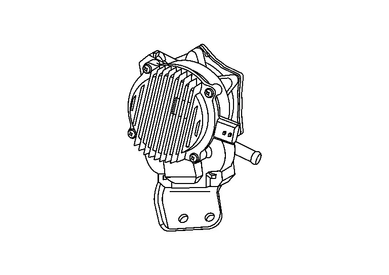
USA PRODUCTION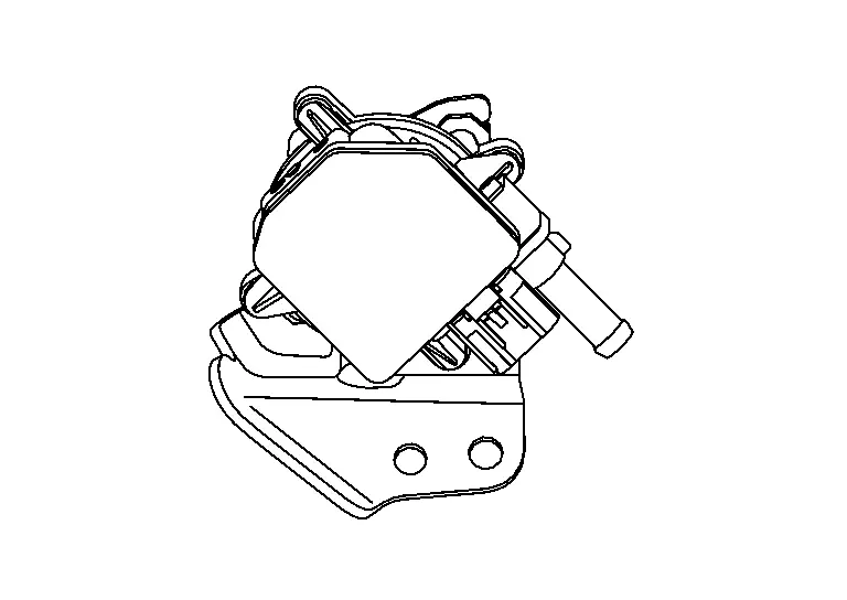
EVAP Canister Purge Volume Control Solenoid Valve
The EVAP canister purge volume control solenoid valve uses a ON/OFF duty to control the flow rate of fuel vapor from the EVAP canister. The EVAP canister purge volume control solenoid valve is moved by ON/OFF pulses from the ECM. The longer the ON pulse, the greater the amount of fuel vapor that will flow through the valve.
FUNCTIONS WITHIN THE SYSTEM
The EVAP canister purge volume control solenoid valve controls the purge flow of fuel evaporative gas inside the EVAP canister based on the ON/OFF duty signal from the ECM.
INDIVIDUAL FUNCTION WITHIN THE SYSTEM
The EVAP canister purge volume control solenoid valve opens and closes the EVAP line between the EVAP canister and intake manifold.
INDIVIDUAL OPERATION
When the solenoid turns ON/OFF, the EVAP canister purge volume control solenoid valve opens and closes. A longer ON pulse increases the purge flow of fuel evaporative gas passing through the solenoid valve.
COMPONENT PARTS LOCATION
The EVAP canister purge volume control solenoid valve is installed to the upper of intake manifold.
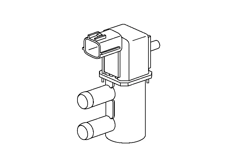
EVAP Canister Vent Control Valve
The EVAP canister vent control valve is located on the EVAP canister and is used to seal the canister vent.
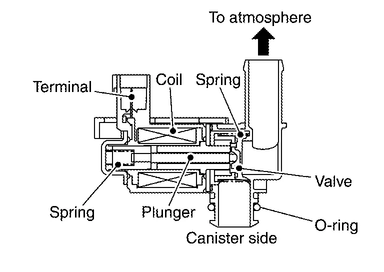
This solenoid valve responds to signals from the ECM. When the ECM sends an ON signal, the coil in the solenoid valve is energized. A plunger will then move to seal the canister vent. The ability to seal the vent is necessary for the on board diagnosis of other evaporative emission control system components.
This solenoid valve is used only for diagnosis, and usually remains opened.
When the vent is closed, under normal purge conditions, the evaporative emission control system is depressurized and allows ŌĆ£EVAP Control SystemŌĆØ diagnosis.
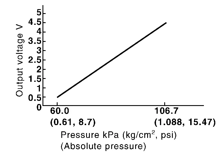
EVAP Control System Pressure Sensor
The EVAP control system pressure sensor detects pressure in the purge line. The sensor output voltage to the ECM increases as pressure increases.
Exhaust Camshaft Position Sensor
FUNCTIONS WITHIN THE SYSTEM
Exhaust camshaft position sensor detects the protrusion of signal plate installed to the exhaust camshaft rear end.
INDIVIDUAL FUNCTION WITHIN THE SYSTEM
The ECM inputs the voltage change caused by the change in magnetic field generated close to the exhaust camshaft position sensor, and the timing of the change, as signal voltage.
INDIVIDUAL OPERATION
The exhaust camshaft position sensor consists of a permanent magnet and Hall IC. When engine is running, the high and low parts of the teeth cause the gap with the sensor to change. The changing gap causes the magnetic field near the sensor to change. Due to the changing magnetic field, the voltage from the sensor changes.
COMPONENT PARTS LOCATION
The exhaust camshaft position sensor is installed on the engine rear side.
Exhaust Valve Timing Control Solenoid Valve
Exhaust valve timing control solenoid valve is activated by ON/OFF pulse duty (ratio) signals from the ECM.
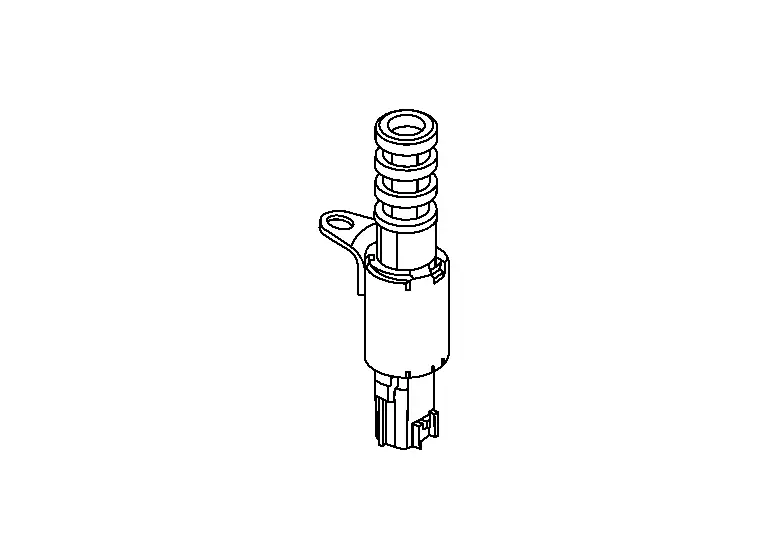
The exhaust valve timing control solenoid valve changes the oil amount and direction of flow through exhaust valve timing control unit or stops oil flow.
The longer pulse width retards valve angle.
The shorter pulse width advances valve angle.
When ON and OFF pulse widths become equal, the solenoid valve stops oil pressure flow to fix the exhaust valve angle at the control position.
Exhaust Valve Timing Intermediate Lock Control Solenoid Valve
Exhaust valve timing intermediate lock control solenoid valve is activated by ON/OFF signals from the ECM.
The exhaust valve timing intermediate lock control solenoid valve opens/closes the path of oil pressure acting on the lock key in the camshaft sprocket (EXH).
-
When the solenoid valve becomes ON, oil pressure to the lock key is drained to perform intermediate lock.
-
When the solenoid valve becomes OFF, oil pressure is acted on the lock key to release the intermediate lock.
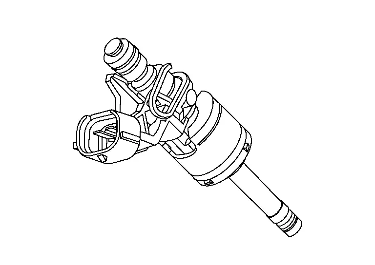
Direct Fuel Injector
FUNCTIONS WITHIN THE SYSTEM
The direct fuel injectors directly injects atomized high-pressure fuel into the cylinders. The injector driver is inside the ECM and drives the direct fuel injectors by means of high voltage (maximum approximately 65 V).
INDIVIDUAL FUNCTION WITHIN THE SYSTEM
The direct fuel injectors inject the high-pressure fuel directly into the cylinders in an extremely short amount of time.
INDIVIDUAL OPERATION
The direct fuel injectors inject the fuel as a mist that allows it to combust efficiently.
COMPONENT PARTS LOCATION
A direct fuel injector is installed on each cylinder.
Fuel Level Sensor Unit, Fuel Pump and FPCM (Fuel pump control module)
FUEL PUMP
The low pressure fuel pump build into the fuel tank.
The ECM turns the fuel pump relay ON/OFF and controls the low-pressure fuel pump.
The low pressure fuel pump is integrated with a fuel pressure regulator and a fuel filter.
When the ignition switch is turned ON, the fuel pump operates for 1 second to start the engine. During cranking and while the engine is running, the fuel pump relay turns ON to operate the low pressure fuel pump, and gasoline inside the fuel tank is sent to the fuel line after passing through the fuel filter. When the fuel pressure in the fuel line reaches or exceeds the specified pressure, the low pressure fuel regulator opens, and the gasoline in the fuel line returns to the fuel tank, lowering the fuel pressure.
| Vehicle condition | Fuel pump operation |
|---|---|
| Ignition switch is turned to ON | Operates for 1 seconds |
| Engine cranking and running | Operates |
| When engine is stopped | Stops in 1.5 seconds |
| Except as shown above | Stops |
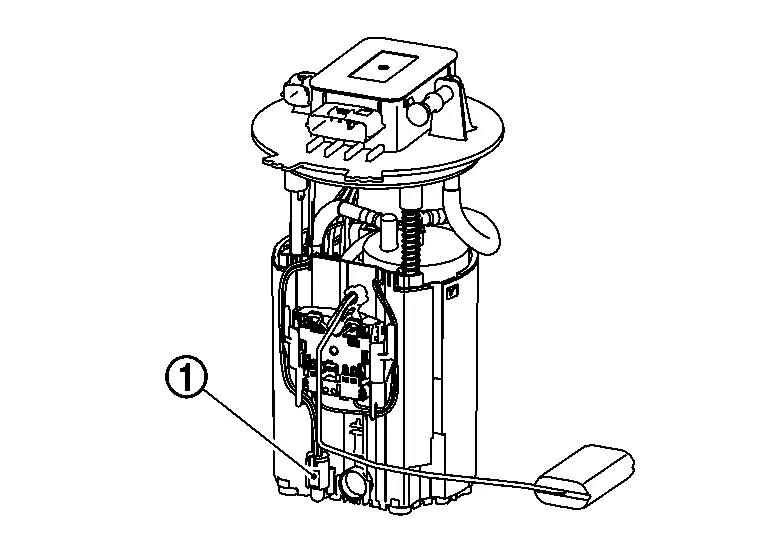
FUEL LEVEL SENSOR
The fuel level sensor  is mounted in the fuel level sensor unit.
 : : |
Fuel pump control module (FPCM) |
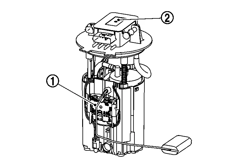
The sensor detects a fuel level in the fuel tank and transmits a signal to the combination meter. The combination meter sends the fuel level sensor signal to the ECM via the CAN communication line.
It consists of two parts, one is mechanical float and the other is variable resistor. Fuel level sensor output voltage changes depending on the movement of the fuel mechanical float.
FPCM (Fuel Pump Control Module)
The fuel pump control module (FPCM)
controls the fuel pump to satisfy a discharge rate suitable to a
driving condition, according to the control from ECM. This reduces the
electricity consumption of fuel pump during low load.
| : |
Fuel level sensor |
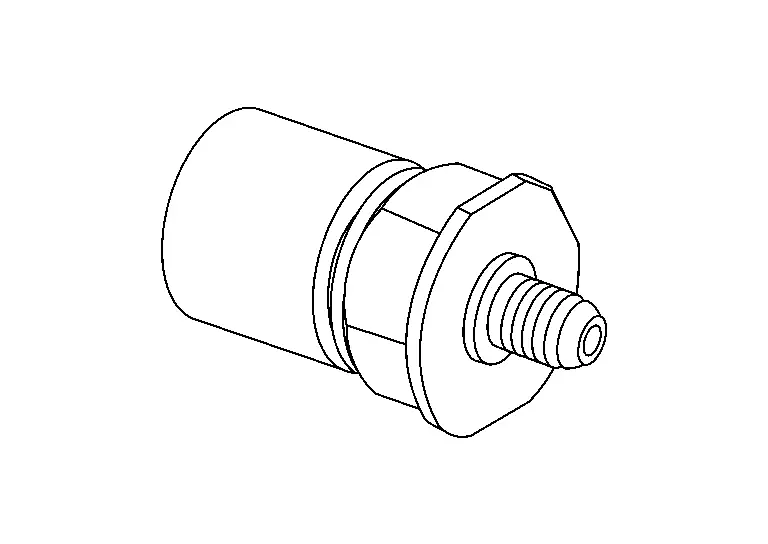
Fuel Rail Pressure Sensor
The fuel rail pressure (FRP) sensor is placed to the fuel rail and measures fuel pressure in the fuel rail. The sensor transmits voltage signal to the ECM. As the pressure increases, the voltage rises. The ECM controls the fuel pressure in the fuel rail by operating high pressure fuel pump. The ECM uses the signal from fuel rail pressure sensor as a feedback signal.
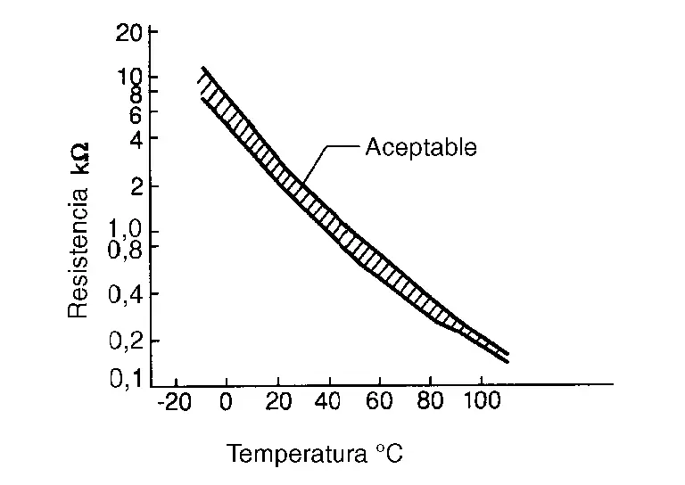
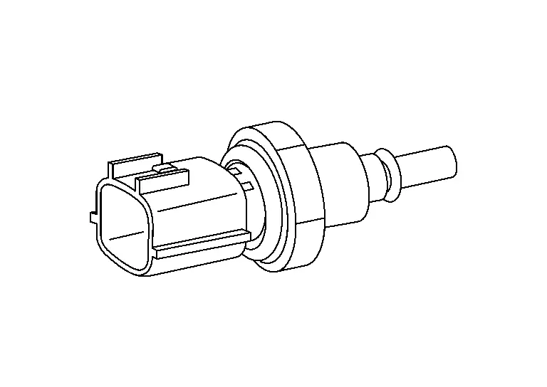
Fuel Tank Temperature Sensor
The fuel tank temperature sensor (FTT sensor)
is used to detect the fuel temperature inside the fuel tank. The sensor
modifies a voltage signal from the ECM. The modified signal returns to
the ECM as the fuel temperature input. The sensor uses a thermistor
which is sensitive to the change in temperature. The electrical
resistance of the thermistor decreases as temperature increases.
<Reference data>
|
Fluid temperature [┬░C (┬░F)] | Voltage* (V) | Resistance (kŌä”) |
|---|---|---|
| 20 (68) | 3.5 | 2.3 ŌĆō 2.7 |
| 50 (122) | 2.2 | 0.79 ŌĆō 0.90 |
*: These data are reference values on the diagnosis tool.
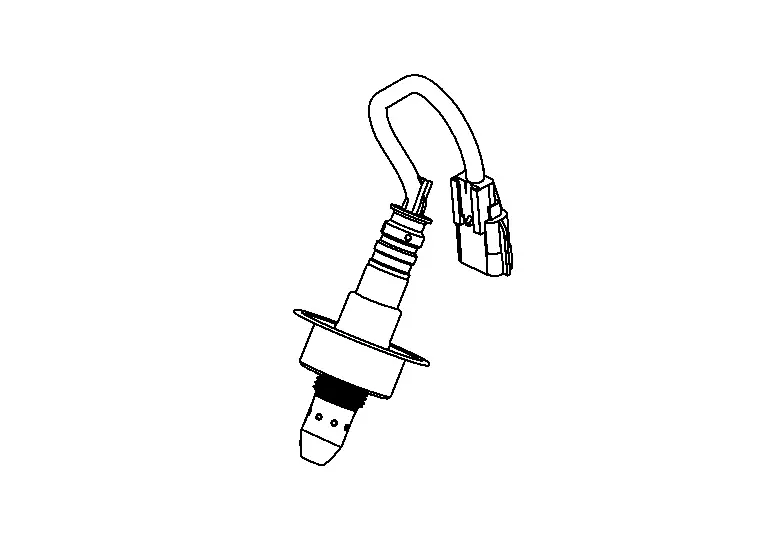
Heated Oxygen Sensor 2
FUNCTIONS WITHIN THE SYSTEM
Heated oxygen sensor 2 detects the oxygen concentration in the exhaust gases, converts it to a voltage signal, and transmits the signal to the ECM. Heated oxygen sensor 2 contains a heater for maintaining its activation.
INDIVIDUAL FUNCTION WITHIN THE SYSTEM
Heated Oxygen Sensor 2
Under normal conditions, heated oxygen sensor 2 is not used for engine control. When A/F sensor 1 is malfunctioning, the signal from heated oxygen sensor 2 is used to control the A/F ratio to the stoichiometric ratio.
Heated Oxygen Sensor 2 Heater
The heated oxygen sensor 2 heater activates heated oxygen sensor 2.
INDIVIDUAL OPERATION
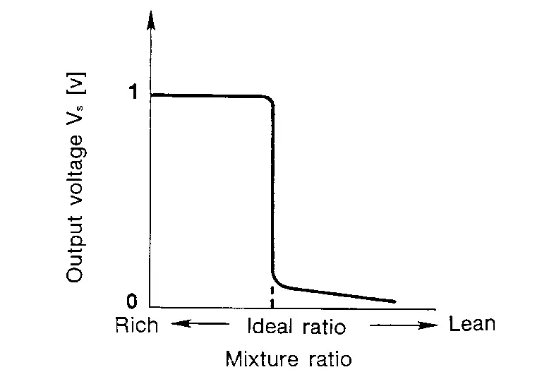
Heated Oxygen Sensor 2
Heated oxygen sensor 2 is composed of a zirconia element in a test tube shape, and is exposed to the atmosphere on the inside and the exhaust gases on the outside. When there is a difference in the oxygen concentration between the inside and outside, electromotive force is generated. When the A/F ratio is leaner than the stoichiometric ratio, the voltage is approximately 0 V. When it is richer, the voltage is approximately 1 V.
Heated Oxygen Sensor 2 Heater
The ECM performs ON/OFF control of the heated oxygen sensor 2 heater corresponding to the engine speed, amount of intake air and engine coolant temperature.
| Engine speed | Heated oxygen sensor 2 heater |
|---|---|
| Above 3,600 rpm | OFF |
|
Below 3,600 rpm after the following conditions are met.
|
ON |
COMPONENT PARTS LOCATION
The heated oxygen sensor 2 is installed on the downstream side of three way catalyst (manifold).
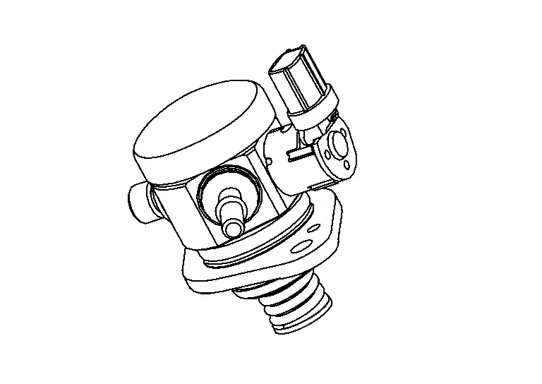
High Pressure Fuel Pump
-
Balanced flow volume control type single cylinder high pressure fuel pump, which approximately equalize the amount of injection and pump output, is adopted.
-
The high pressure fuel pump is activated by the exhaust camshaft. ECM controls the high pressure fuel pump control solenoid valve built into the high pressure fuel pump and adjusts the amount of discharge by changing the suction timing of the low pressure fuel.
-
Inflow process: Cam driven lowering plunger let the fuel from low pressure fuel pump induced into high pressure fuel pump.
-
Spill process: Although the cam driven plunger start moving upward, inflow check valve still at open position due to the control solenoid valve, so the fuel is not pressurized and spilled out to low pressure fuel pump side. By changing the amount of this spill out volume changes the amount of injection.
-
Outflow process: When the control solenoid valve turns ON, the inflow check valve is closed, fuel is pressurized and when the pressure exceeds certain point discharge check valve is pushed open to discharge fuel into fuel rail.
-
Operating Description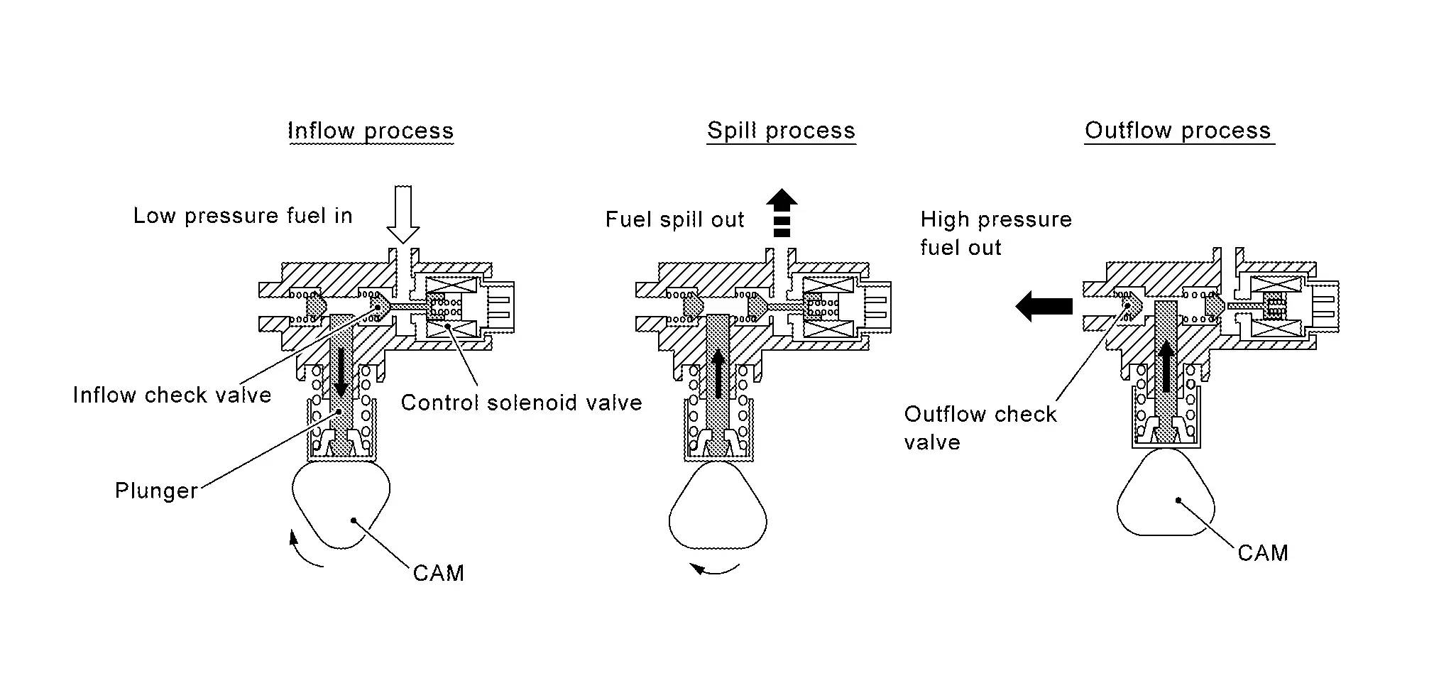
Operating Chart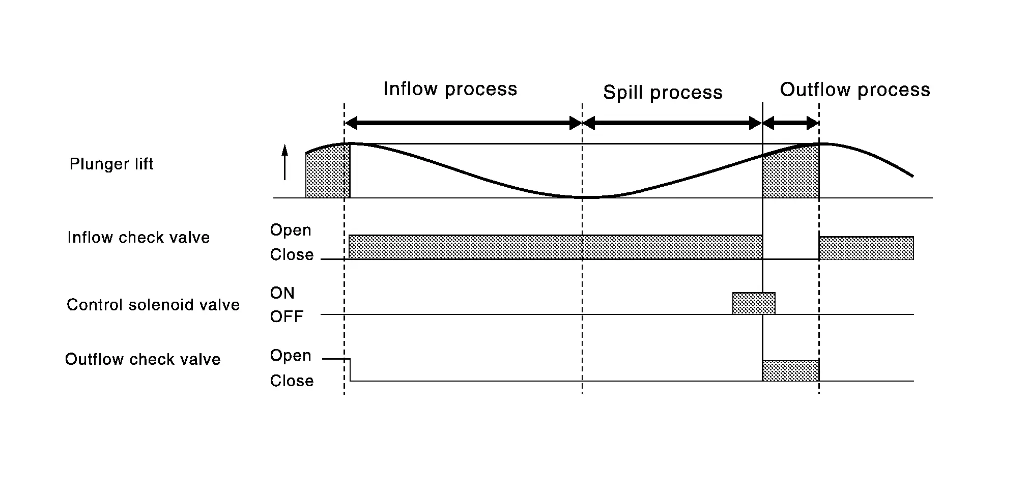
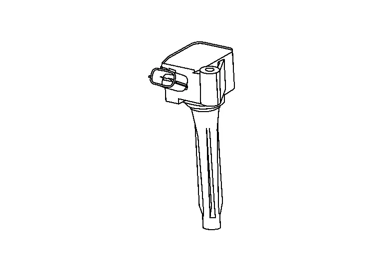
Ignition Coil With Power Transistor
Ignition coil with power transistor
The ignition signal from the ECM is sent to and amplified by the power transistor. The power transistor turns ON and OFF the ignition coil primary circuit. This ON/OFF operation induces the proper high voltage in the coil secondary circuit.
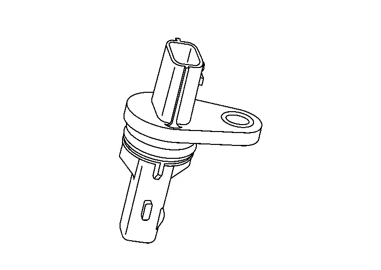
Intake Camshaft Position Sensor
The ECM identifies the cylinders from the combination of the intake camshaft position sensor signal and the crankshaft position sensor signal input into it.
This sensor signal is used for sensing a position of the intake camshaft.
The sensor consists of a permanent magnet and Hall IC.
When engine is running, the high and low parts of the teeth cause the gap with the sensor to change.
The changing gap causes the magnetic field near the sensor to change.
Due to the changing magnetic field, the voltage from the sensor changes.
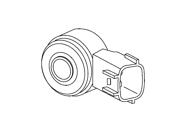
Knock Sensor
The knock sensor is attached to the cylinder block. It senses engine knocking using a piezoelectric element. A knocking vibration from the cylinder block is sensed as vibrational pressure. This pressure is converted into a voltage signal and sent to the ECM.
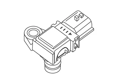
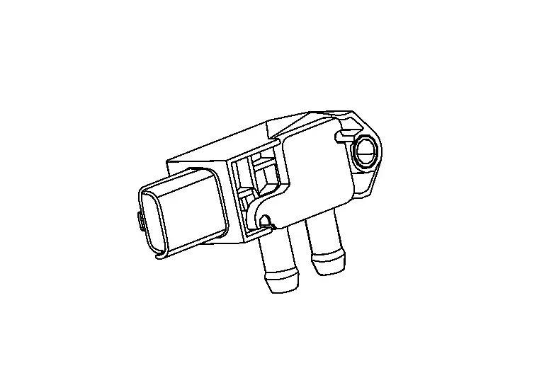
Manifold Absolute Pressure Sensor
The manifold absolute pressure (MAP) sensor is placed at intake manifold collector. It detects intake manifold pressure and sends the voltage signal to the ECM.
The sensor uses a silicon diaphragm which is sensitive to the change in pressure. As the pressure increases, the voltage rises.
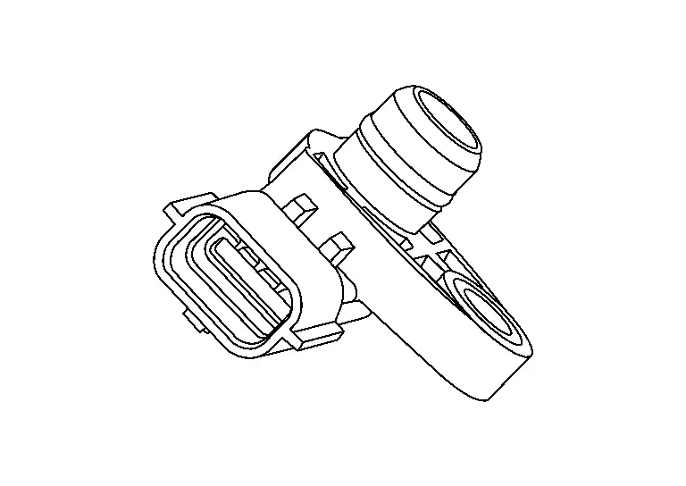
Mass Air Flow Sensor
MASS AIR FLOW SENSOR
Mass air flow sensor is installed to the intake air path upstream of throttle and measures air flow rate.
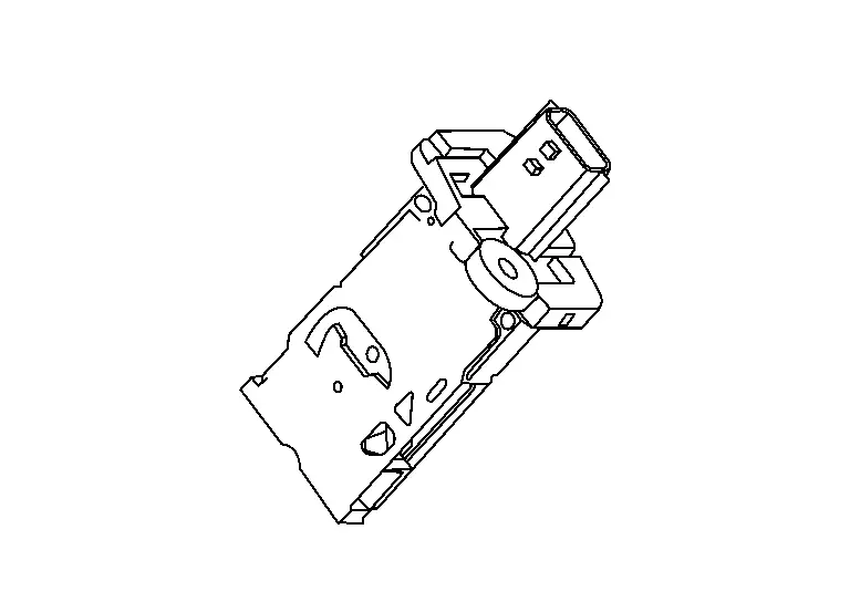
This mass air flow sensor is a backflow-detecting film and silicon element type sensor that can detects air flow rate of both direct flow and backflow. This mass air flow sensor outputs an air flow rate by using frequency signals.
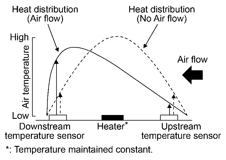
The element part of this mass air flow sensor consists of a heater and temperature sensors that are installed to both top and bottom of the heater, one to each position. When air flows, the heat distribution around the heater changes and this produces a temperature difference between upstream and downstream. This temperature difference is detected as air flow rate.
INTAKE AIR TEMPERATURE SENSOR, HUMIDITY SENSOR, HUMIDITY TEMPERATURE SENSOR
The Mass air flow sensor has a built-in intake air temperature sensor, humidity sensor and humidity temperature sensor.
Each sensor detects temperature and humidity and transmits signals to the ECM.
The Intake air temperature sensor uses a thermistor that is sensitive to temperature changes.
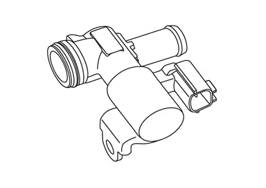
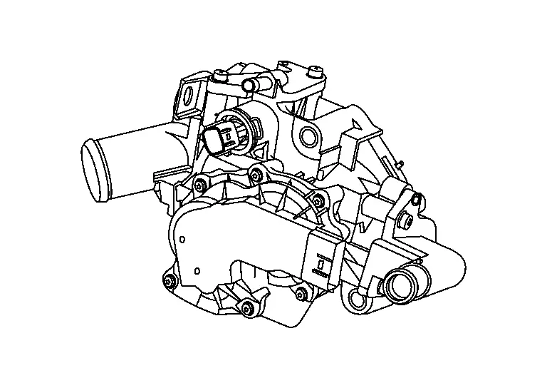
Multi-way Control Valve
The multi-way control valve changes flow paths to Heater, Engine oil cooler & CVT oil warmer, and Radiator, according to coolant temperature and driving conditions.
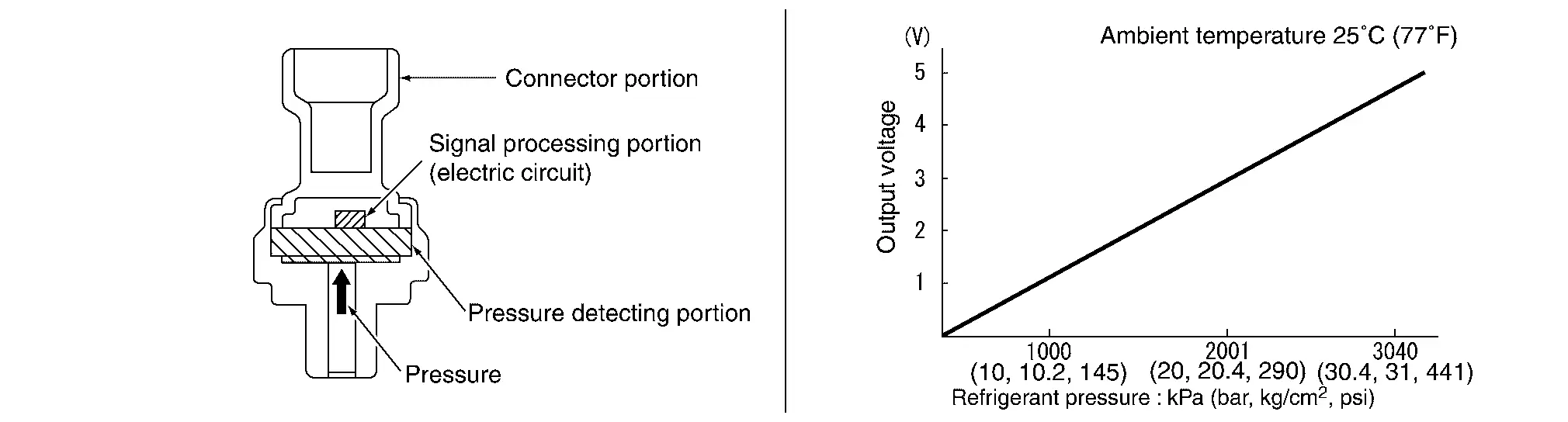
Refrigerant Pressure Sensor
The refrigerant pressure sensor is installed at the liquid tank of the air conditioner system. The sensor uses an electrostatic volume pressure transducer to convert refrigerant pressure to voltage. The voltage signal is sent to ECM, and ECM controls cooling fan system.
Stop Lamp Switch
Stop lamp switch is installed to brake pedal bracket.
ECM detects the state of the brake pedal by those two types of input (ON/OFF signal).
| Brake pedal | Connector | Status |
|---|---|---|
| Released | 1 ŌĆō 2 | OFF |
| 3 ŌĆō 4 | ON | |
| Depressed | 1 ŌĆō 2 | ON |
| 3 ŌĆō 4 | OFF |
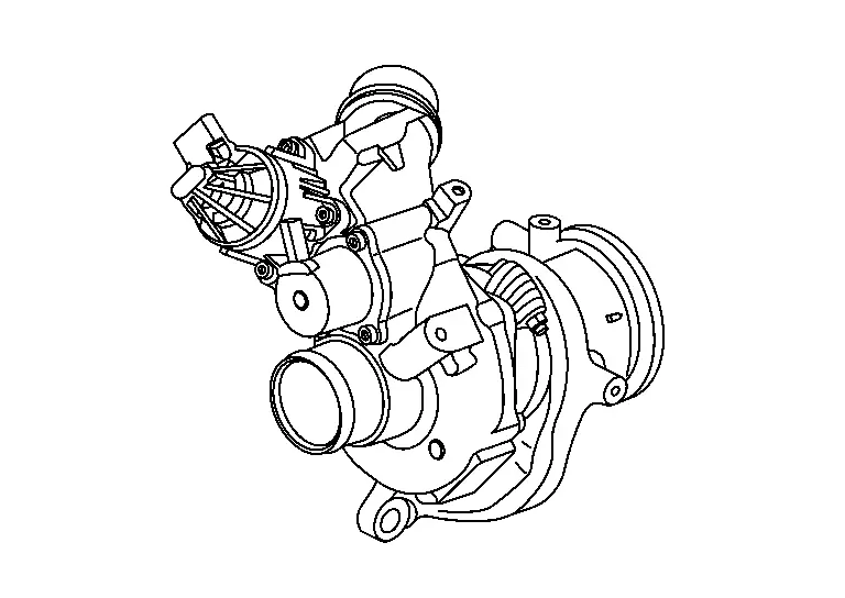
Turbocharger
TURBOCHARGER BOOST CONTROL
The electric wastegate control actuator operates based on a signal from ECM and adjusts the turbo charger boost control valve angle via link rod. The electronic control allows the turbocharger wastegate control valve to be opened even in non-supercharging regions. This reduces pumping losses and contributes to the fuel economy. In charging regions, wastegate valve angles are controlled by the electronic control with a high degree of accuracy.
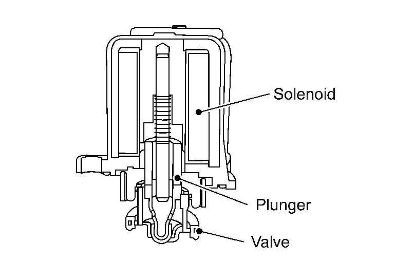
TURBOCHARGER BYPASS CONTROL
When an operating signal received from ECM energizes the solenoid, the turbocharger bypass control valve opens the valve by sucking in the plunger. The electronically-controlled turbocharger bypass control valve quickly opens the bypass valve when releasing the accelerator pedal during driving under supercharge. This reduces surge sound generated by the back flow of supercharged air to the compressor fin.
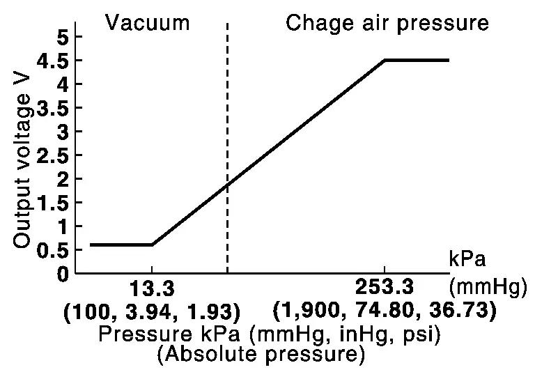
Turbocharger Boost Sensor (With Intake Air Temperature Sensor 2)
TURBOCHARGER BOOST SENSOR
The turbocharger boost sensor detects the pressure of the outlet side of the intercooler. When increasing the pressure, the output voltage of the sensor to the ECM increases.
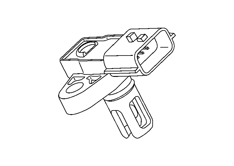
INTAKE AIR TEMPERATURE SENSOR 2
The intake air temperature sensor 2 is built-into turbocharger boost sensor. The sensor detects intake air temperature and transmits a signal to the ECM.
The temperature sensing unit uses a thermistor which is sensitive to the change in temperature. Electrical resistance of the thermistor decreases in response to the temperature rise.
<Reference data>
|
Intake air temperature [┬░C (┬░F)] | Voltage* (V) | Resistance (kŌä”) |
|---|---|---|
| 25 (77) | 3.159 - 3.291 | 1.94 - 2.06 |
| 80 (176) | 1.118 - 1.262 | 0.301 - 0.333 |
*: These data are reference values and are measured between ECM terminals.
Variable Compression Ratio Actuator
FUNCTIONS WITHIN THE SYSTEM
The compression rate of engine is changed according to the signal from VCR control module.
INDIVIDUAL FUNCTION WITHIN THE SYSTEM
VCR actuator is operated according to the signal from ECM. The current angle of VCR control shaft 2 is fed back to ECM.
VCR motor
VCR motor rotates VCR control shaft according to the control signal of VCR control module.
VCR motor rotation angle sensor
VCR motor rotation angle sensor send the rotation angle signal of VCR control shaft 2 to VCR CU.
(This signal is utilized to drive VCR motor.)
VCR control shaft 2 rotation angle sensor
When Ignition switch is ON position, VCR control shaft 2 rotation angle sensor reads the position of VCR control shaft 2.
(Reading position is utilized as the trouble diagnosis for VCR motor rotation angle sensor.)
INDIVIDUAL OPERATION
VCR actuator is operated according to the signal from ECM. The current angle of VCR control shaft 2 is fed back to ECM.
COMPONENT PARTS LOCATION
The VCR actuator is installed to the engine left side.
Variable Compression Ratio Control Module
FUNCTIONS WITHIN THE SYSTEM
The compression rate of engine is changed according to the signal from VCR control module.
INDIVIDUAL FUNCTION WITHIN THE SYSTEM
The VCR actuator has a motor and an angle sensor as built-in parts and also has a link connected to the a shaft in the engine.
INDIVIDUAL OPERATION
The compression rate of engine is changed according to changing angle of VCR control shaft which is rotated by VCR motor .
COMPONENT PARTS LOCATION
VCR actuator is installed to front lower side of engine.
Other materials:
Its Can Communication 1 Circuit
Diagnosis Procedure
CHECK NETWORK DIAGNOSIS
Check the "Network diagnosis" results from CONSULT to see that the diagnostic CAN communication circuit have no malfunction.
Are the diagnostic CAN communication circuit normal?
YES>>
GO TO 2.
NO>>
Check and repair diagnostic CAN commu ...
Symptom Diagnosis. Sunshade Does Not Operate Properly
Description
Sunshade does not operate normally.
Sunshade open/close does not operate.
Sunshade open/close operation is slow.
Judder occurs during open/close operation of sunshade.
Diagnosis Procedure
CHECK SUNSHADE
Check sunshade for damage, deformation, of interference with oth ...
Hill Start Assist system
WARNING
Never rely solely on the Hill Start Assist system to keep the Nissan Rogue from rolling backward on a hill. Always remain attentive, apply the brake pedal when stopped on steep inclines, and use extra caution on icy or muddy slopes. Failure to prevent rollback could result in loss of contr ...