Nissan Rogue (T33) 2021-Present Service Manual: Shift Actuator
Exploded View
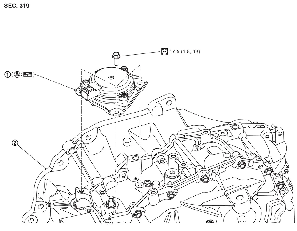
| 1. | Shift actuator | 2. | Transaxle assembly | ||
| A | Spline part |
 : N·m (kg-m, ft-lb)
 : Apply lithium-based grease including molybdenum disulphide
Removal and Installation
REMOVAL
CAUTION:
Be sure that vehicle does not move before removing shift actuator.
-
Apply the parking brake.
-
Shift to the P position (if electric shift system is normal).
Remove 12V battery. Refer to Removal and Installation.
Remove battery tray 1. Refer to Removal and Installation
Remove air cleaner and air duct. Refer to Removal and Installation.
Remove harness clips (A) .
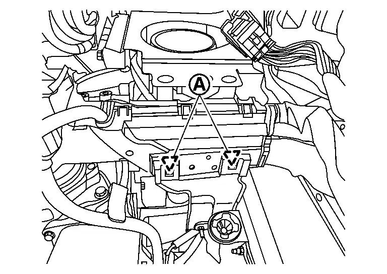
Disconnect the harness connector (A) from the shift actuator.
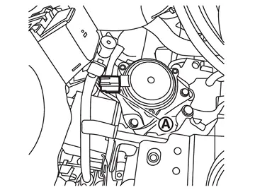
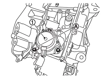
Remove bolts (A) from shift actuator and remove shift actuator (1).
INSTALLATION
CAUTION:
Apply the parking brake.
CAUTION:
Note when the shift actuator is removed while the range is in the P position, and installed while the range is in the N position:
-
Never use remote engine start system immediately after installing shift actuator.
-
Adjust to P range after pressing P switch without operating shift selector after ignition switch ON.
-
Unless the above points are performed, the electric shift control module does not accept the request from the shift lever.
Clean splines of manual shaft and shift actuator before installing shift actuator.
Apply grease evenly to the shift actuator spline (A).
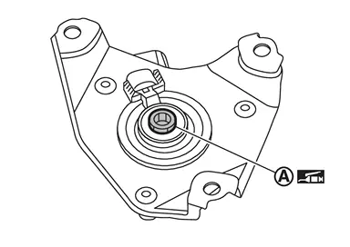
|
: Lithium-based grease including molybdenum disulphide |
Install shift actuator (1) and then tighten shift actuator mounting bolts (A) to the specified torque. Refer to Exploded View.
 NOTE:
NOTE:
Set the manual shaft to the N position before installing the shift actuator.
Connect the harness connectors (A) to the shift actuator.
Install harness clips (A) .
Install air duct and air cleaner. Refer toExploded View.
Install battery tray. Refer to Removal and Installation.
Install 12V battery. Refer to Removal and Installation.
Connect the negative battery terminal. Refer to Exploded View.
Ignition switch ON and press the P position switch.
Learn shift actuator after installation. Refer to Description.
Perform inspection after installation. Refer to Inspection.
Inspection
INSPECTION AFTER INSTALLATION
Check the CVT position. Refer to Inspection.
Other materials:
Limites du système de détecteur de collision frontale intelligent
Illustration A
Illustration B
Illustration C
Illustration D
AVERTISSEMENT
Les limites du système de détecteur de collision frontale intelligent du Nissan Rogue sont décrites ci-dessous. Le non-respect de ces limites lors de la conduite peut entraîner des blessures gr ...
Basic information
The following are approximate capacities for your Nissan Rogue.
Actual refill capacities may vary slightly. When refilling, always follow the procedure described in the "8. Do-it-yourself" section to confirm the proper amount for your Nissan Rogue.
Fuel
Engine oil
Drain and refill
Genuine "NI ...
Dtc/circuit Diagnosis. B2001-45 Intelligent Key Unit
DTC Description
DTC DETECTION LOGIC DTC No.
CONSULT screen items
(Trouble diagnosis content) DTC Detection Condition
B2001-45
Intelligent Key unit
(Intelligent Key unit)
Diagnosis condition
Ignition switch ON
Signal (terminal)
—
Threshold
Intelligent Key unit is ...