
Nissan Rogue (T33) 2021-Present Service Manual: Removal and Installation :: Vanity Mirror Lamp
Exploded View
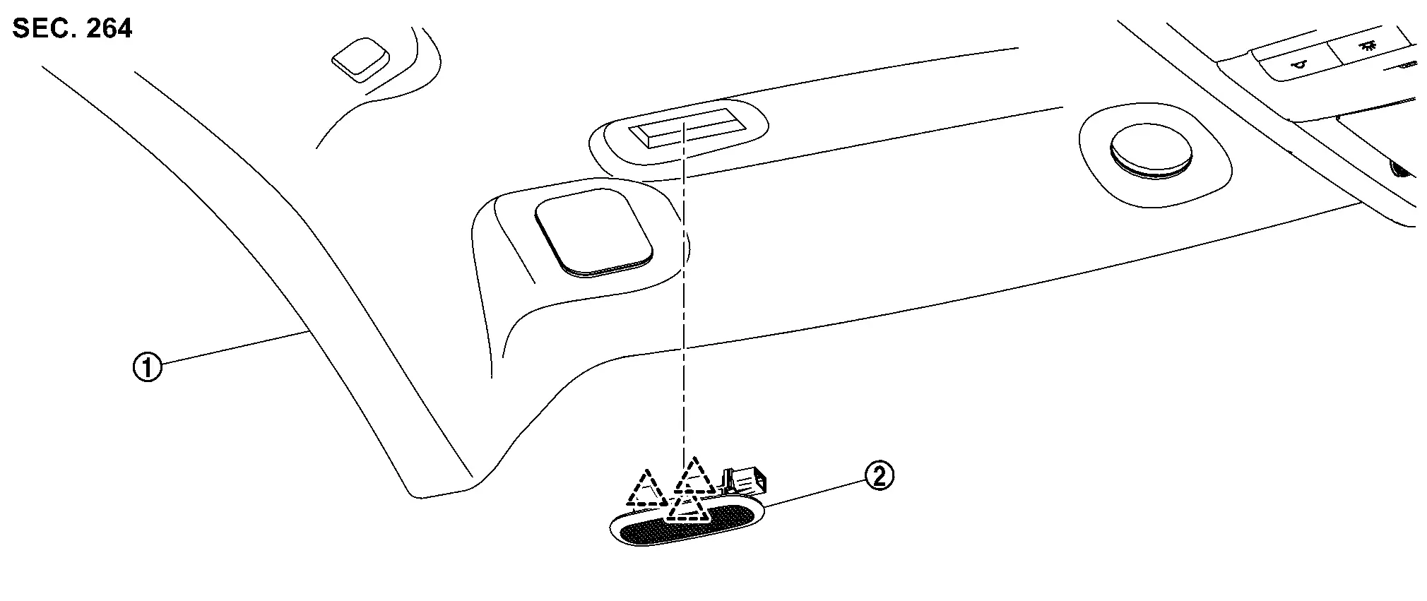
 |
Headlining assembly |  |
Vanity mirror lamp assembly | ||
 |
: Pawl | ||||
Removal and Installation
REMOVAL
CAUTION:
Disconnect the battery negative terminal or remove power circuit fuse when performing the operation for preventing electric leakage. Refer to Precautions for Removing Battery Terminal.
Remove headlining assembly. Refer to Removal and Installation.
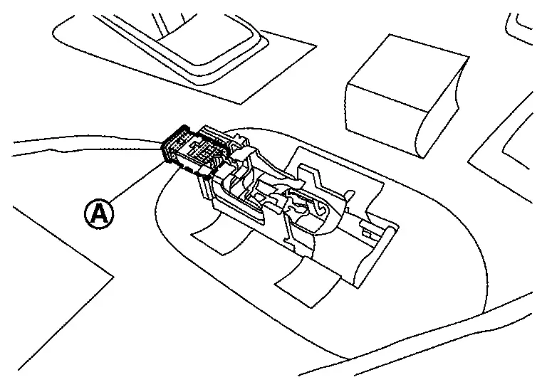
Disconnect harness connector  .
.
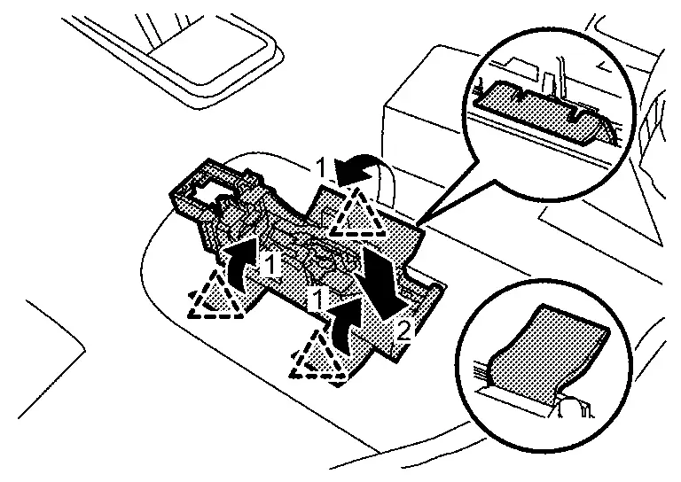
Disengage vanity mirror lamp assembly fixing pawls according to numerical order 1→2 indicated by arrows as shown in the figure, and then remove vanity mirror lamp assembly.
|
: Pawl |
INSTALLATION
Note the following items, and then install in the reverse order of removal.
CAUTION:
-
There is no front-back direction for pawl direction of vanity mirror lamp.
-
Install the harness connector toward the inside of the Nissan Ariya vehicle.
Replacement
VANITY MIRROR LAMP BULB
CAUTION:
-
Disconnect the battery negative terminal or remove power circuit fuse when performing the operation for preventing electric leakage. Refer to Precautions for Removing Battery Terminal.
-
Replace vanity mirror lamp assembly as a set. Refer to Removal and Installation.
Other materials:
P06db Engine Oil Pressure Control Solenoid Valve
DTC Description
DTC DETECTION LOGIC DTC
CONSULT screen terms
(Trouble diagnosis content)
DTC detection condition
P06DB
00
ENGINE OIL PRESSURE CONTROL
(Engine oil pressure control circuit low)
Diagnosis condition
—
Signal (terminal)
Engine oil pressure control so ...
P06b0 Sensor Power Supply 1
DTC Description
DESCRIPTIONECM supplies a voltage of 5 V to some of the
sensors systematically divided into 3 groups, respectively.
Accordingly, when a short circuit develops in a sensor power source, a
malfunction may occur simultaneously in the sensors belonging to the
same group as the s ...
System Description. System (automatic Back Door System)
System Description
SYSTEM DIAGRAMThe
automatic back door system performs the automatic open/close operation
of the back door by operating the automatic back door switch, automatic
back door close switch, automatic back door lock and close switch, back
door opener switch, hands free sensor, ...