Nissan Rogue (T33) 2021-Present Service Manual: Dtc/circuit Diagnosis :: Rear Window Defogger Relay
Component Function Check
CHECK REAR WINDOW DEFOGGER RELAY CONTROL FUNCTION
 CONSULT
-
Ignition switch ON.
-
Select ŌĆ£Rear defoggerŌĆØ in ŌĆ£Active testŌĆØ mode of "BCM".
-
Touch ŌĆ£OnŌĆØ.
-
Check that the back door window glass is getting warmer.
 NOTE:
NOTE:
When glass is hot, never start inspection until it is cool enough.
Is the inspection result normal?
YES>>Rear window defogger relay control function is OK.
NO>>Refer to Diagnosis Procedure.
Diagnosis Procedure
CHECK REAR WINDOW DEFOGGER RELAY (COIL SIDE) CIRCUIT 1
-
Ignition switch OFF.
-
Disconnect BCM connector.
-
Ignition switch ON.
-
Check voltage between BCM harness connector and ground.
(+) (-) Voltage
(Approx.)BCM Connector Terminal M19 (with type B meter) 63 Ground Battery voltage M51 (with type A meter) 35
Is the inspection result normal?
YES>>GO TO 5.
NO>>GO TO 2.
CHECK REAR WINDOW DEFOGGER RELAY (COIL SIDE) CIRCUIT 2
-
Ignition switch OFF.
-
Remove rear window defogger relay.
-
Ignition switch ON.
-
Check voltage between rear window defogger relay terminal and ground.
(+) (-) Voltage
(Approx.)Rear window defogger relay Location Terminal J ŌĆÉ 4 2 Ground Battery voltage
Is the inspection result normal?
YES>>GO TO 3.
NO>>Repair or replace the malfunctioning parts.
CHECK REAR WINDOW DEFOGGER RELAY (COIL SIDE) CIRCUIT 3
-
Ignition switch OFF.
-
Disconnect fuse block (J/B) connector.
-
Check continuity between rear window defogger relay terminal and fuse block (J/B) harness connector.
Rear window defogger relay Fuse block (J/B) Continuity Location Terminal Connector Terminal J ŌĆÉ 4 1 M68 16F Yes
Is the inspection result normal?
YES>>GO TO 4.
NO>>Repair or replace harness.
CHECK REAR WINDOW DEFOGGER RELAY (COIL SIDE) CIRCUIT 4
-
Ignition switch OFF.
-
Check continuity between BCM harness connector and fuse block (J/B) harness connector.
| BCM | Fuse block (J/B) | Continuity | ||
|---|---|---|---|---|
| Connector | Terminal | Connector | Terminal | |
| M19 (with type B meter) | 63 | M68 | 16F | Yes |
| M51 (with type B meter) | 35 | |||
Is the inspection result normal?
YES>>GO TO 7.
NO>>Repair or replace harness.
CHECK REAR WINDOW DEFOGGER RELAY (SWITCH SIDE) CIRCUIT 1
-
Ignition switch OFF.
-
Remove rear window defogger relay.
-
Check voltage between rear window defogger relay terminal and ground.
(+) (-) Voltage
(Approx.)Rear window defogger relay Location Terminal J ŌĆÉ 4 3 Ground Battery voltage
Is the inspection result normal?
YES>>GO TO 6.
NO>>Repair or replace the malfunctioning parts.
CHECK REAR WINDOW DEFOGGER RELAY (SWITCH SIDE) CIRCUIT 2
-
Disconnect fuse block (J/B) connector.
-
Check continuity between fuse block (J/B) harness connector and rear window defogger relay terminal.
Fuse block (J/B) Rear window defogger relay Continuity Connector Terminal Location Terminal B28 1L J ŌĆÉ 4 5 Yes
Is the inspection result normal?
YES>>GO TO 7.
NO>>Repair or replace fuse block (J/B).
CHECK REAR WINDOW DEFOGGER RELAY
Check rear window defogger relay. Refer to Component Inspection.
Is the inspection result normal?
YES>>Inspection End.
NO>>Replace rear window defogger relay.
Component Inspection
CHECK REAR WINDOW DEFOGGER RELAY
-
Ignition switch OFF.
-
Remove rear window defogger relay.
-
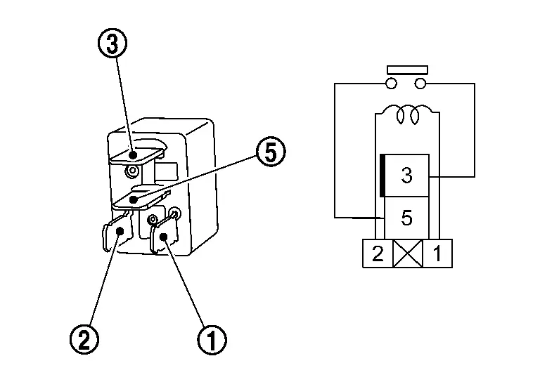
Check continuity between rear window defogger relay terminals.
| Terminal | Condition | Continuity | |
|---|---|---|---|
|
Rear window defogger relay | |||
 |
 |
12 V direct current supply between terminals  and and  . . |
Yes |
| No current supply | No | ||
Is the inspection result normal?
YES>>Inspection End.
NO>>Replace rear window defogger relay.
Other materials:
Contr├┤le dynamique
Informations de base
Le contr├┤le dynamique du Nissan Rogue est un module ├®lectronique avanc├® regroupant plusieurs fonctions destin├®es ├Ā am├®liorer la stabilit├®, le confort et la tenue de route.
Syst├©me de contr├┤le en virage intelligent
Contr├┤le actif de suspension (selon lŌĆÖ├®quipem ...
Ecu Diagnosis Information. Moonroof Motor Assembly
Reference Value
TERMINAL LAYOUTPHYSICAL VALUES
Terminal No.
(Wire color) Description Condition
Value
(Approx.)
+ ŌĆō Signal name Input/Output
1
(B)
Ground
Ground
ŌĆö
ŌĆö
0 V
4
(W)
Ground
Moonroof Tilt UP signal
Input
Moonroof switch
Operate
( ...
Rear View Monitor. Preparation. Preparation
Preparation
Commercial Service Tools
Tool Description
Power tool
Loosening screws
...