Nissan Rogue (T33) 2021-Present Service Manual: Removal and Installation :: Vacuum Lines
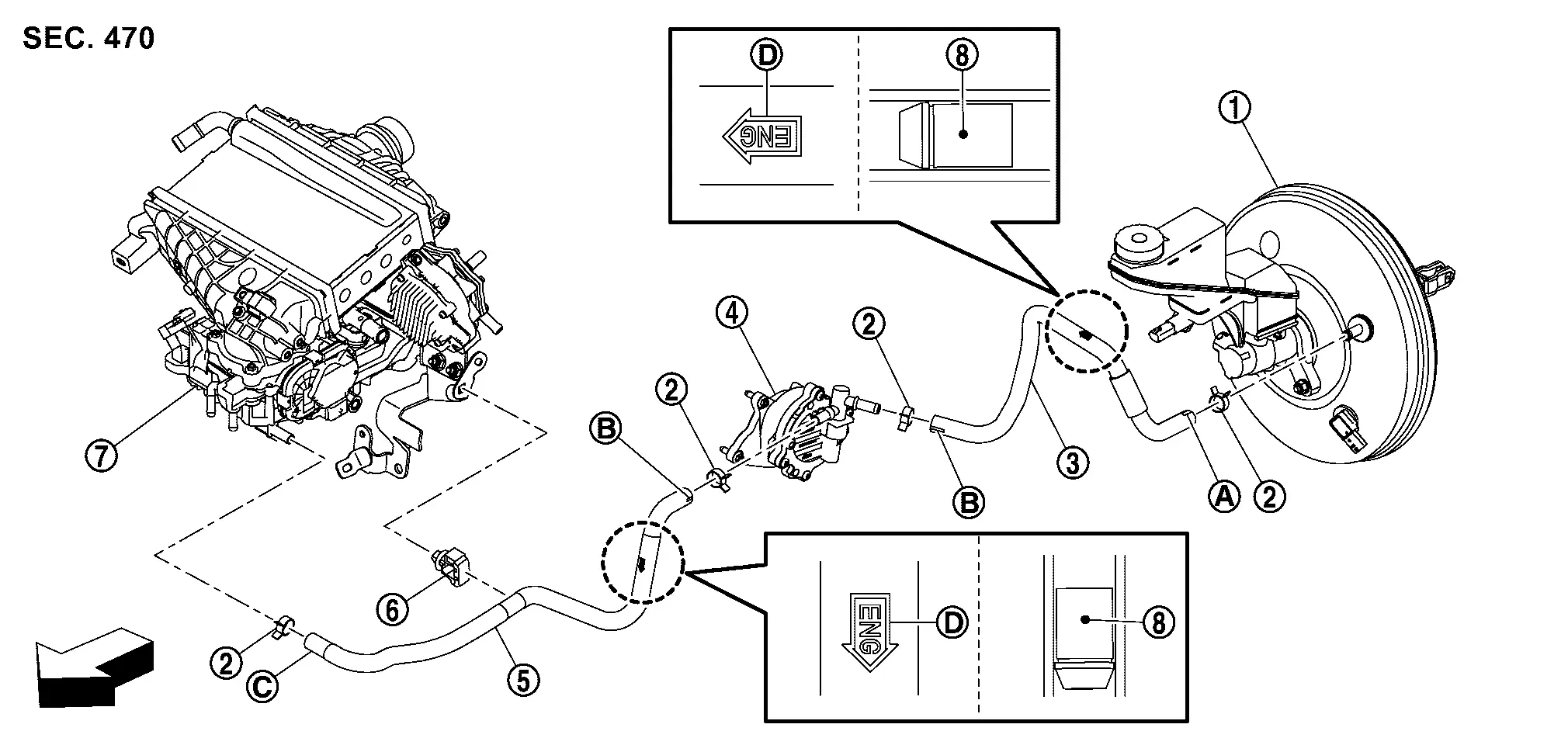
Exploded View
 |
Brake booster |  |
Clamp |  |
Vacuum hose 1 |
 |
Vacuum pump |  |
Vacuum hose 2 |  |
Clip |
 |
Intake manifold |  |
Check valve | ||
 |
Paint mark (White) |  |
Paint mark (Pink) |  |
Paint mark (Yellow) |
 |
Stamp indicating the direction of engine (Yellow) | ||||
| : Nissan Ariya Vehicle front | |||||
Removal and Installation
REMOVAL
Remove 12V battery. Refer to Removal and Installation.
Remove vacuum hose 1.
Remove EVAP canister purge volume control solenoid valve mounting bolts, and then secure the work space.
Remove vacuum hose 2 from clip.
Perform inspection after removal. Refer to Inspection.
INSTALLATION
Installation is in the reverse order of removal.
 NOTE:
NOTE:
When the insertion of vacuum hose is difficult, applying volatile alcohol shall be acceptable. However the volatile alcohol shall be composed from ethanol, n-propyl alcohol and isopropyl alcohol.
-
When installing vacuum hoses, insert it until its tip reaches the back-end of length (A) or further as shown in the figure.
A : 24 mm (0.95 in) or more -
Pink marking (1) should face Nissan Ariya vehicle front side and vacuum hose should be inserted until spool (2).
-
Make sure the stamp (B) indicating the direction of engine.
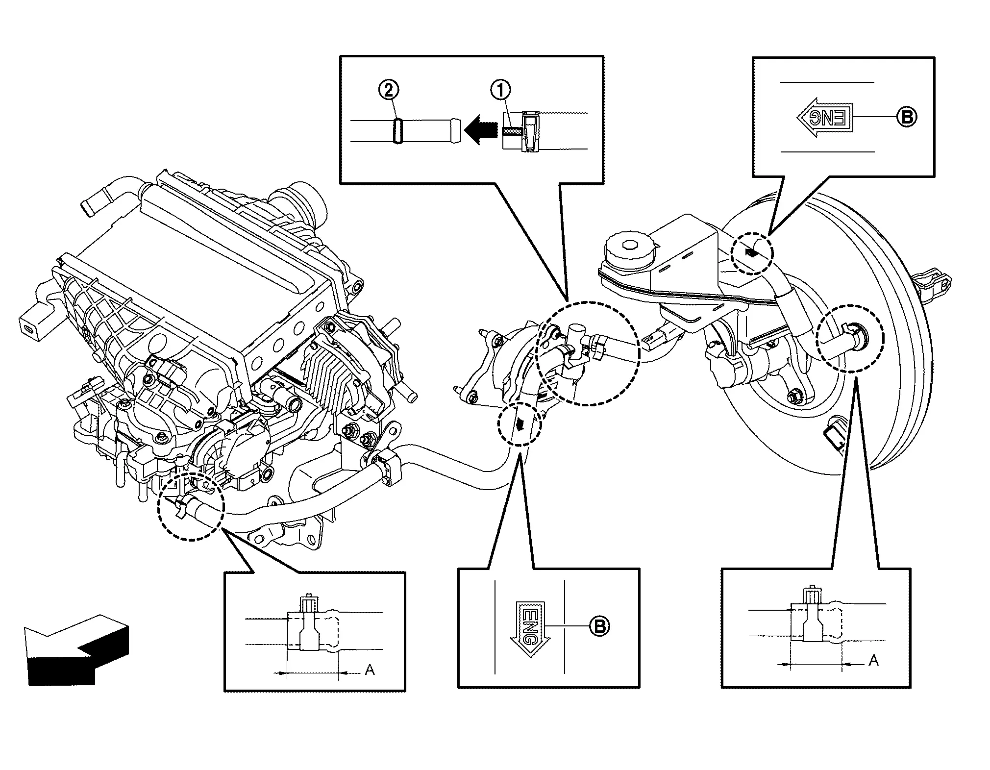

: Nissan Ariya Vehicle front
-
Face the paint mark (white) of vacuum hose 1 (brake booster side) to upward assemble.
-
Face the paint mark (pink) of vacuum hose 1 and 2 (vacuum pump side) to horizontal assemble.
-
Face the paint mark (yellow) of vacuum hose 2 (intake manifold side) to downward assemble.
-
For clamp mounting direction (the orientation of pawl), refer to Exploded View (KR15DDT).
Inspection
INSPECTION AFTER REMOVAL
Appearance
Check for correct assembly, damage and deterioration.
Check Valve Airtightness
-
Use a handy vacuum pump (commercial service tool) (A) to check.
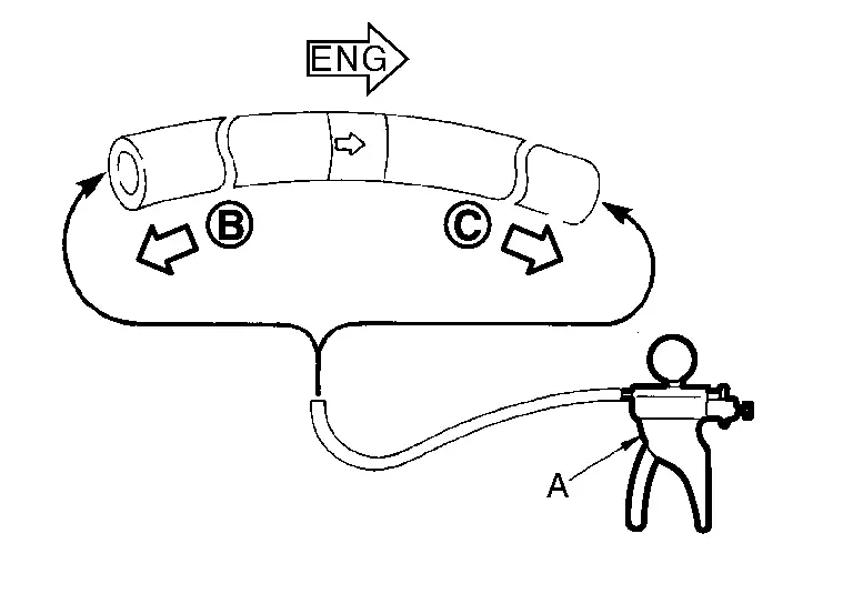
When connected to the booster side : Vacuum should decrease within 1.3 kPa (9.8 mmHg, 0.38 inHg) for 15 seconds under a vacuum of ā€“66.7 kPa (ā€“500 mmHg, ā€“19.70 inHg). When connected to the engine side : Vacuum should not exist. -
Replace vacuum hose assembly if vacuum hose and check valve are malfunctioning.
Other materials:
How to Erase Permanent Dtc
Description
OUTLINEWhen a DTC is stored in control moduleWhen
a DTC is stored in control module and MIL is ON, a permanent DTC is
erased with MIL shutoff if the same malfunction is not detected after
performing the driving pattern for MIL shutoff three times in a raw. *1:
When the same mal ...
Limites du systĆØme LDW
AVERTISSEMENT
Les limites du systĆØme LDW du Nissan Rogue sont dĆ©crites ci-dessous. Le non-respect des instructions et avertissements relatifs Ć lā€™utilisation correcte du systĆØme LDW peut entraĆ®ner des blessures graves, voire mortelles.
Le systĆØme LDW ne fonctionne pas lorsque la vites ...
P2251 Ho2s2
DTC Description
To judge malfunctions, the diagnosis checks that the A/F signal
computed by ECM from the A/F sensor 1 signal fluctuates according to
fuel feedback control.DTC DETECTION LOGIC DTC
CONSULT screen terms
(Trouble diagnosis content)
DTC detection condition
P2251
00
...