Nissan Rogue (T33) 2021-Present Service Manual: Removal and Installation :: Brake Booster
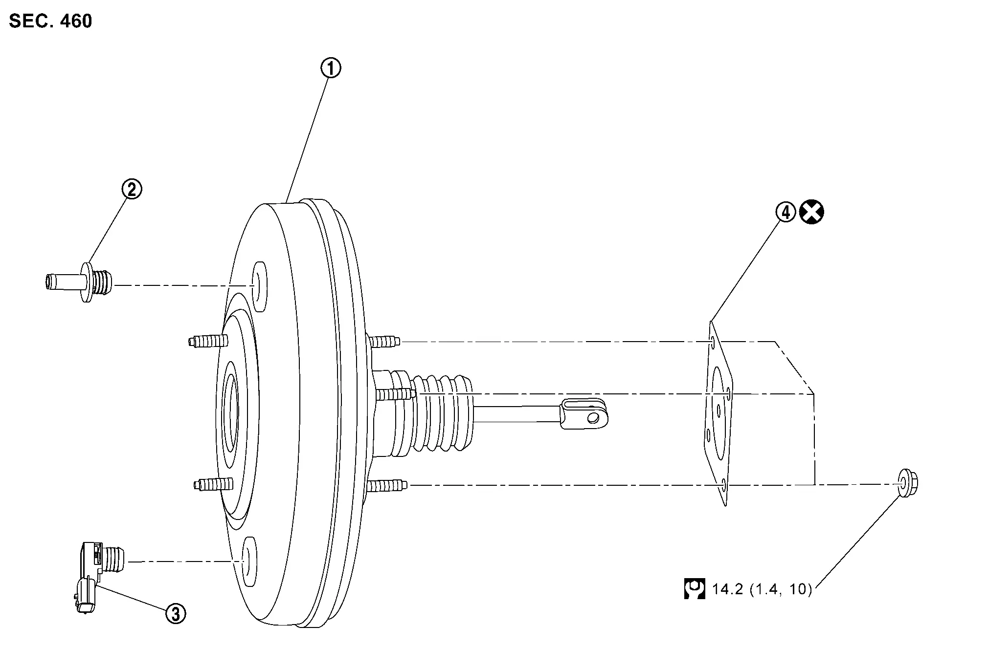
Exploded View
 |
Brake booster |  |
Joint pipe |  |
Vacuum sensor |
 |
Gasket | ||||
 |
: N┬Àm (kg-m, ft-lb) | ||||
 |
: Always replace after every disassembly. | ||||
Removal and installation
REMOVAL
CAUTION:
Never spill or splash brake fluid on painted surfaces. Brake fluid may seriously damage paint. Wipe it off immediately and wash with water if it gets on a painted surface. For brake component parts, never wash them with water.
Perform inspection before removal. Refer to Inspection and Adjustment.
Remove engine under cover. Refer to Removal and Installation.
Drain engine coolant. Refer to Draining.
Remove cowl top extension. Refer to Removal and Installation.
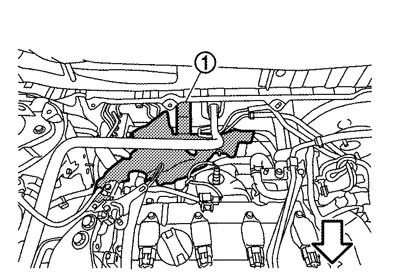
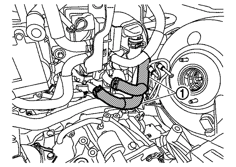
Remove heat insulator (1).
Remove brake tube between master cylinder assembly and ABS actuator and electric unit (control unit). Refer to Exploded View.
Remove 12V battery tray. Refer to Removal and Installation.
Remove brake master cylinder assembly. Refer to Removal and Installation.
Remove vacuum hose from joint pipe. Refer to Removal and Installation (KR15DDT).
If needed remove joint pipe.
Disconnect the vacuum sensor harness connector.
If needed remove vacuum sensor.
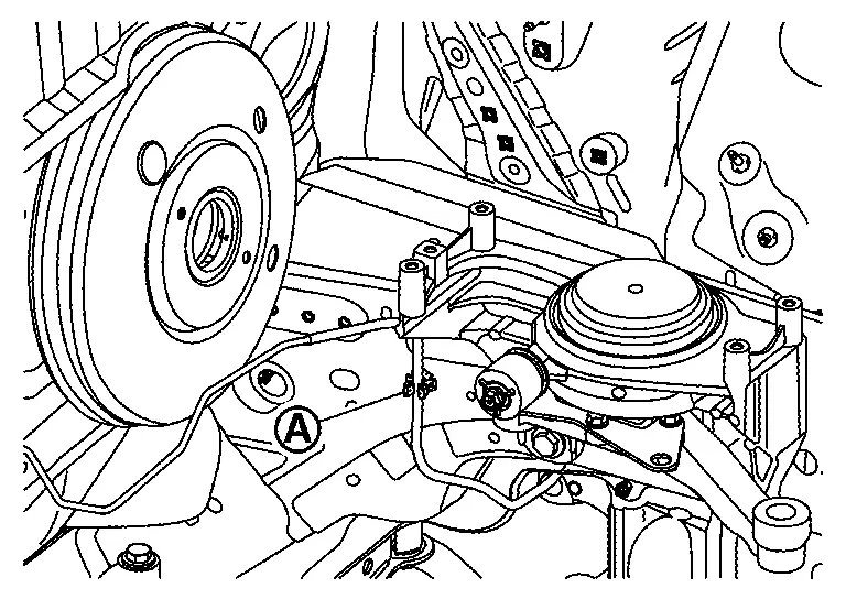
Remove brake tube from clip (A).
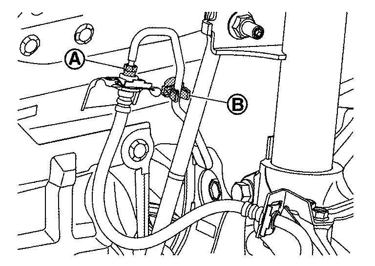
Remove flare nut (A) and brake tube from clip (B), and then remove brake tube.
Remove heater hoses (1).
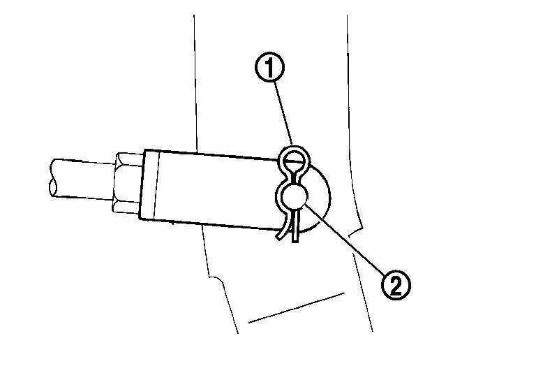
Remove snap pin (1) and clevis pin (2).
Remove nuts on brake booster and brake pedal assembly.
CAUTION:
Hold the brake booster so as to avoid dropping out.
Remove brake booster.
CAUTION:
Never deform or bend the brake tubes.
Perform inspection after removal. Refer to Inspection and Adjustment.
INSTALLATION
CAUTION:
Never spill or splash brake fluid on painted surfaces. Brake fluid may seriously damage paint. Wipe it off immediately and wash with water if it gets on a painted surface. For brake component parts, never wash them with water.
Note the following, and install in the reverse order of removal.
-
Install check valve (1) as shown in figure.
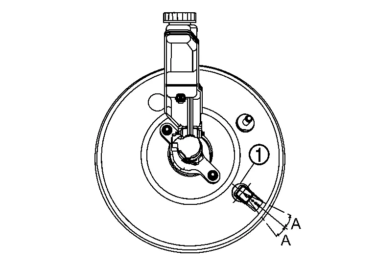
A : ┬▒ 15┬░ -
Be careful not to damage brake booster stud bolt threads. If brake booster is tilted during installation, the dash panel may damage threads.
-
Never deform or bend the brake tubes when installing the brake booster.
-
Always use new gasket between the brake booster and the dash panel.
-
Replace clevis pin when found damage.
-
Never allow foreign matter (e.g.dust) and oil other than brake fluid to enter reservoir tank.
-
Refill engine coolant. Refer to Refilling.
-
Perform the air bleeding. Refer to Bleeding Brake System.
CAUTION:
Never reuse brake fluid to drain.
-
Check each item of brake pedal. Adjust it if the measurement value is not the standard. Refer to Inspection and Adjustment.
Inspection and Adjustment
INSPECTION BEFORE REMOVAL
Air Tight
CAUTION:
Check the air tight condition when the master cylinder and the brake booster is installed.
Check the air tight use a handy vacuum pump.
| At vacuum of 66.7 kPa (500 mmHg, 19.69 inHg, 0.067 bar) | : Vacuum should decrease within 3.3 kPa (24.8 mmHg, 0.98 inHg, 0.033 bar) for 15 seconds. |
If the air tight condition cannot be maintained, perform the following operation.Check the no dirt and dust are present on the brake booster and brake master cylinder mating faces. Clean it if necessary. Check the O-ring on the master cylinder. If anything is found, replace the O-ring. Refer to Removal and Installation. Check the air tight condition again. If the condition still cannot be maintained, replace the brake booster.
INSPECTION AFTER REMOVAL
Input Rod Length rod Inspection
Check the input length (A).
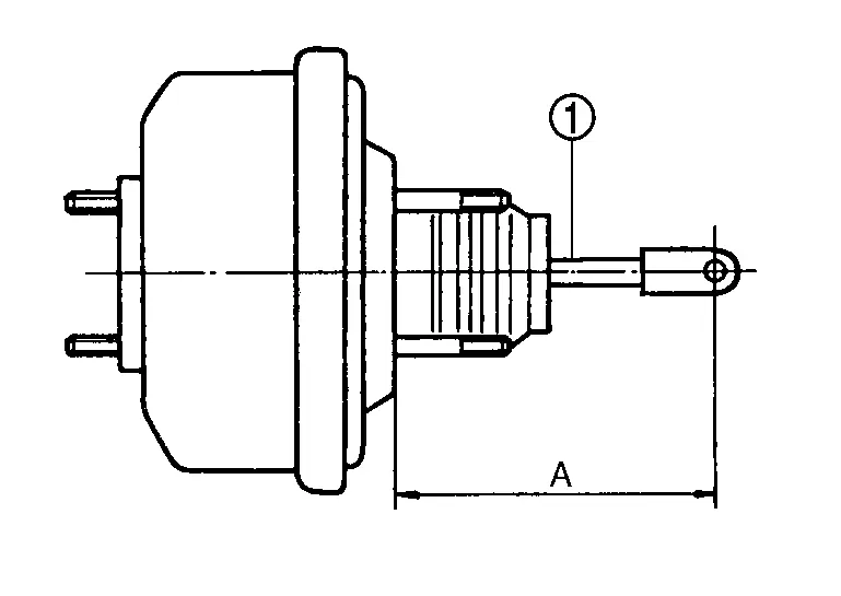
|
: Input rod |
| A | : Refer to Brake Booster. |
Replace the brake booster if the input rod length is not the standard.
INSPECTION AFTER INSTALLATION
Operation
Depress the brake pedal several times at 5-second intervals with the engine stopped. Start the engine with the brake pedal fully depressed. Check that the clearance between brake pedal and dash lower panel decreases.
 NOTE:
NOTE:
A slight impact with a small click may be felt on the pedal when the brake pedal is fully depressed. this is normal phenomenon due to the brake system operation.
Air Tight
Run the engine at idle for 1 minute to apply vacuum to the brake booster, and stop the engine.
Depress the brake pedal several times at 5-second intervals until the accumulated vacuum is released to atmospheric pressure. Check that the clearance between brake pedal and dash lower panel gradually increases each time.
Depress the brake pedal with the engine running. Then stop the engine while holding down the brake pedal. Check that the brake pedal stroke does not change after holding down the brake pedal for 30 seconds or more.
ADJUSTMENT AFTER INSTALLATION
Perform the brake pedal adjustment after installing the brake pedal assembly. Refer to Inspection and Adjustment.
Other materials:
Removal and Installation. 12v Battery Current Sensor
Exploded View
: 12V battery current sensor
: Harness connector
: N┬Àm (kg-m, in-lb)
Removal and Installation
REMOVALDisconnect the 12V battery current sensor connector .
Remove negative cable mounting nut , and then remove the negative cable .
Loosen 12V battery cu ...
Removal and Installation. Vanity Mirror Lamp
Exploded View
Headlining assembly
Vanity mirror lamp assembly
: Pawl
Removal and Installation
REMOVALCAUTION:
Disconnect the battery negative terminal or remove power
circuit fuse when performing the operation for preventing electric
leakage. Refer to Prec ...
U1ca2-08 Lin Communication 3
DTC Description
DTC DETECTION LOGIC DTC No.
CONSULT screen terms
(Trouble diagnosis content) DTC detection condition
U1CA2-08
LIN communication 3
(Local interconnect network communication 3)
Diagnosis condition
Ignition switch ON
Signal (Terminal)
LIN (door motor) signal
...