Nissan Rogue (T33) 2021-Present Service Manual: Removal and Installation :: Brake Master Cylinder
Without Propilot Assist 2.1
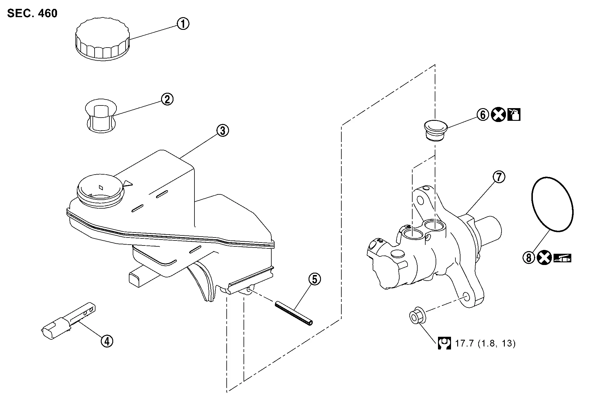
Exploded View
 |
Reservoir cap |  |
Oil strainer |  |
Reservoir tank |
 |
Brake fluid level switch |  |
Pin |  |
Grommet |
 |
Cylinder body |  |
O-ring | ||
 |
: N·m (kg-m, ft-lb) | ||||
 |
: Apply brake fluid. | ||||
 |
: Apply polyglycol ether based lubricant. | ||||
 |
: Always replace after every disassembly. | ||||
Removal and Installation
REMOVAL
CAUTION:
-
Never spill or splash brake fluid on painted surfaces. Brake fluid may seriously damage paint. Wipe it off immediately and wash with water if it gets on a painted surface. For brake component parts, never wash them with water.
-
Depress the brake pedal several times to release the vacuum pressure from the brake booster. Then remove the master cylinder assembly.
-
Never depress the brake pedal while removing the brake tube. If this is not complied with, brake fluid may splash.
Perform inspection before removal. Refer to Inspection.
Drain brake fluid. Refer to Draining.
Remove the 12V battery. Refer to Removal and Installation.
Remove the engine cover (if so equipped). Refer to Removal and Installation.
Disconnect the brake fluid level switch harness connector.
Secure the work space by fixing the fuel hose and canister hose with ropes.
Separate the brake tube (1) from the master cylinder assembly (2) with a flare nut wrench (A).
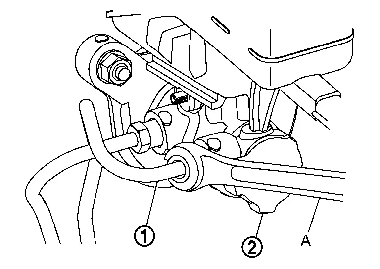
CAUTION:
Never scratch the flare nut and the brake tube.
Remove the master cylinder assembly.
CAUTION:
-
Never deform or bend the brake tubes.
-
Never depress the brake pedal after the master cylinder assembly is removed.
-
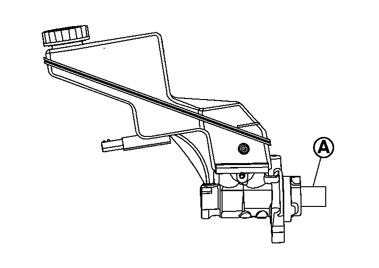
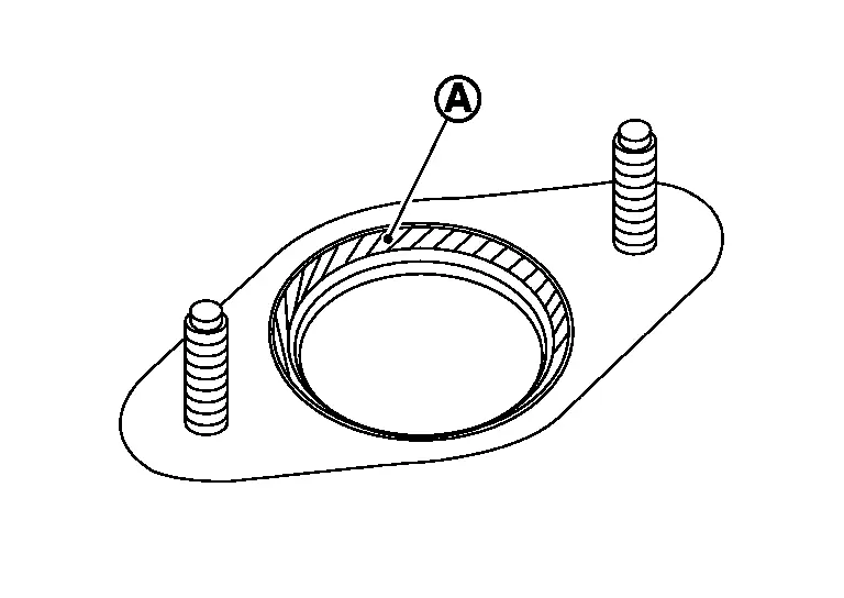
The piston (A) of the master cylinder assembly is exposed. Never damage it when removing the master cylinder.
-
The piston may drop off when pulled out strongly. Never hold the piston. Hold the cylinder body when handling the master cylinder assembly.
Remove the O-ring.
INSTALLATION
CAUTION:
Never spill or splash brake fluid on painted surfaces. Brake fluid may seriously damage paint. Wipe it off immediately and wash with water if it gets on a painted surface. For brake component parts, never wash them with water.
Installation is in the reverse order of removal.
-
Never reuse the O-ring.
-
Never depress the brake pedal after the master cylinder assembly is removed.
-
Apply polyglycol ether based lubricant to the brake booster [see (A) in the figure] when installing the master cylinder assembly to the brake booster.
-
The piston (A) of the master cylinder assembly is exposed. Never damage it when handling the master cylinder.
-
Check that no dirt and dust are present on the piston before installation. Clean it with new brake fluid if necessary.
-
The piston may drop off when pulled strongly. Never hold the piston. Hold the cylinder body when handling the master cylinder assembly.
-
Never deform or bend the brake tubes.
-
Temporarily tighten the brake tube (1) flare nut to the master cylinder assembly (2) by hand. Then tighten it to the specified torque with a flare nut torque wrench (A). Refer to Exploded View.
-
Perform the air bleeding. Refer to Bleeding Brake System.
-
Perform inspection after installation. Refer to Inspection.
Disassembly and Assembly
DISASSEMBLY
CAUTION:
-
Never disassemble the cylinder body.
-
Remove the reservoir tank only when necessary.
-
Never drop parts to remove. Replace new parts when dropping.
Fix the master cylinder assembly to a vise.
CAUTION:
-
Always set copper plates or cloth between vise grips when fixing the cylinder body to a vise.
-
Never overtighten the vise.
Remove the reservoir tank mounting screw.
Remove the reservoir tank and grommet from the cylinder body.
ASSEMBLY
CAUTION:
-
Never use mineral oils such as kerosene or gasoline and rubber grease during the cleaning and assembly process.
-
Never allow foreign matter (e.g. dust) and oils other than brake fluid to enter the reservoir tank.
-
Never drop when installing. The parts must not be reused if they are dropped.
Apply new brake fluid to the grommet and install it to the cylinder body.
CAUTION:
Never reuse grommets.
Install the reservoir tank to the cylinder body.
Fix the cylinder body to a vise.
CAUTION:
-
Place the reservoir tank with the chamfered screw hole (
 ) facing up.
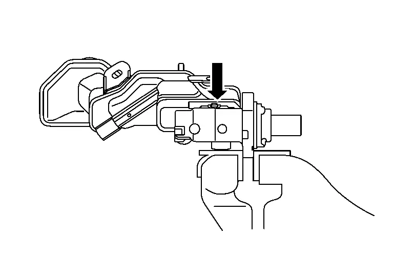
-
Always set copper plates or cloth between vise grips when fixing the cylinder body to a vise.
-
Never overtighten the vise.
Tilt the reservoir tank so that a mounting screw can be fixed. Assemble with screw.
Inspection
INSPECTION BEFORE REMOVAL
Check the brake fluid level switch. Refer to Component Inspection.
INSPECTION AFTER INSTALLATION
Check the following items and replace if necessary.
-
Check the master cylinder for deformation, twist, contact with other parts or looseness of connection.
-
Check for fluid leakage from connection. Refer to Inspection.
CAUTION:
If the fluid leakage is present, retighten to the specified torque. Replace parts if necessary.
With Propilot Assist 2.1
Exploded View
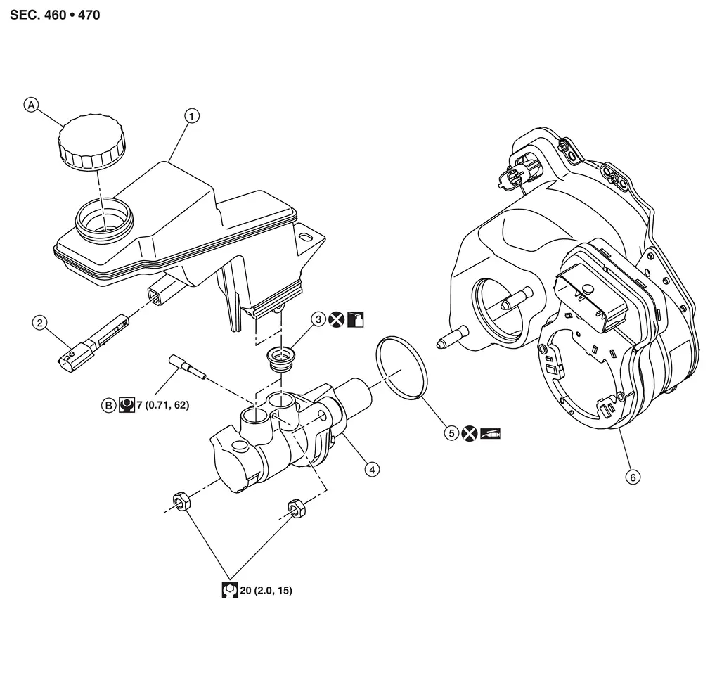
| 1 | Reservoir tank | 2 | Brake fluid level switch | 3 | Grommet |
| 4 | Master cylinder | 5 | O-ring | 6 | Electrically-driven intelligent brake unit. Refer to Exploded View. |
| A | Reservoir cap | B | Screw | ||
| : Apply polyglycol ether based lubricant. |
|||||
| : Apply brake fluid. |
|||||
Removal and Installation
REMOVAL
CAUTION:
-
Do not allow brake fluid to adhere to painted surfaces such as the body. If it adheres, it may damage the paint film. Wipe off quickly and wash with water. However, avoid washing the brake components with water.
-
During brake tube removal and installation work, do not depress the brake pedal, the brake fluid may splash.
Perform inspection before removal of brake master cylinder. Refer to Inspection.
Remove the battery tray 1. Refer to Removal and Installation.
Disconnect the brake fluid level switch harness connector.
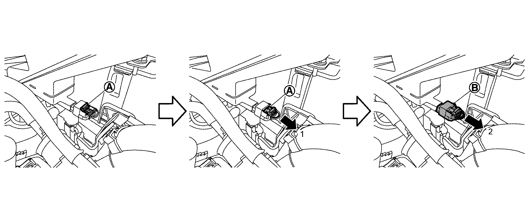
If necessary, remove the brake fluid level switch as follows:
-
Pin punch hole on the reservoir tank bottom side (general purpose tool: pin punch a: 4 mm) using claw to push up, remove the brake fluid level switch from the reservoir tank.
CAUTION:
Never scratch the flare nut and the brake tube.
Separate the harness retainer from the reservoir tank.
Drain the brake fluid. Refer to Draining.
Using flare nut wrench, loosen the flare nut and remove the brake tube from the brake master cylinder assembly. Refer to Exploded View.
CAUTION:
-
Do not damage the flare nut and brake tube.
Remove the brake master cylinder assembly nuts and remove the brake master cylinder assembly from the electrically-driven intelligent brake unit.
CAUTION:
-
Do not deform or bend the brake tube when removing the brake master cylinder assembly.
-
Do not depress the brake pedal while the brake master cylinder assembly is removed.
-
The piston (A) of the master cylinder assembly is exposed. Never damage it when removing the master cylinder.
-
Hold the cylinder body when handling the brake master cylinder assembly, not the piston. Since the piston may detach from assembly if pulled strongly.
Remove the O-ring.
INSTALLATION
CAUTION:
-
Do not allow brake fluid to adhere to painted surfaces such as the body. If it adheres, it may damage the coating film, so quickly wipe it off and wash with water. However, avoid washing the brake components with water.
-
Do not depress the brake pedal while installing or removing the brake tube, as brake fluid may splash.
-
Do not depress the brake pedal while the brake master cylinder assembly is removed.
Pay attention to the following work and carry out the removal procedure in reverse order:
-
Do not reuse O-rings.
-
Install the brake fluid level switch if it was removed.
-
Do not scratch the piston part (A) since the piston of the brake master cylinder assembly is exposed.
-
The piston (A) of the master cylinder assembly is exposed. Never damage it when handling the master cylinder.
-
Confirm that there is no dirt or dust adhering to the piston. Also, when cleaning, use new brake fluid.
-
Hold the cylinder body when handling the brake master cylinder assembly, not the piston. Since the piston may detach from assembly if pulled strongly.
-
Do not deform or bend the brake tube when installing the brake master cylinder assembly.
-
Temporarily tighten the flare nut of the brake tube to the brake master cylinder assembly by hand. Then use the flare nut torque wrench (general-purpose tool). Tighten to the specified torque using flare nut wrench. Refer to Exploded View.
-
CAUTION:
Do not damage the flare nut and brake tube.
-
Refill with new brake fluid and perform the air bleeding. Refer to Bleeding Brake System.
-
Perform inspection after installation. Refer to Inspection.
-
Disassembly and Assembly
DISASSEMBLY
CAUTION:
-
Never disassemble the cylinder body.
-
Remove the reservoir tank only when necessary.
-
Never drop parts to remove. Replace new parts when dropping.
Fix the master cylinder assembly to a vise.
CAUTION:
-
Always set copper plates or cloth between vise grips when fixing the cylinder body to a vise.
-
Never overtighten the vise.
Remove the reservoir tank mounting screw.
Remove the reservoir tank and grommets from the cylinder body.
ASSEMBLY
CAUTION:
-
Never use mineral oils such as kerosene or gasoline and rubber grease during the cleaning and assembly process.
-
Never drop the when installing. The parts must not be reused if they are dropped.
-
Never allow foreign matter (e.g. dust) and oils other than brake fluid to enter the reservoir tank.
Apply new brake fluid to the grommets and install the grommets to the master cylinder body.
CAUTION:
Never reuse the grommets.
Install the reservoir tank to the master cylinder.
Fix the master cylinder to a vise.
CAUTION:
-
Place the reservoir tank with the chamfered pin hole facing up.
-
Always set copper plates or cloth between vise grips when fixing the master cylinder to a vise.
-
Never overtighten the vise.
Install the screw and tighten to the specification. Refer to Exploded View.
Inspection
INSPECTION BEFORE REMOVAL
Check the brake fluid level switch. Refer to Component Inspection.
INSPECTION AFTER INSTALLATION
Inspect the following items, and replace if any abnormality is found:
-
Check for scratches, twists, deformations, interference with other parts, and loose connections.
-
Check for fluid leakage from connection. Refer to Inspection.
CAUTION:
If fluid leakage occurs, re-tighten each part to the specified torque, and replace if any abnormality is found.
Other materials:
Other supplemental front-impact air bag precautions
WARNING
Do not place any objects on the steering wheel pad or instrument panel. Do not place objects between any occupant and the steering wheel or instrument panel. These may turn into dangerous projectiles if the front air bags deploy.
Do not place sharp-edged objects or heavy items on ...
Brake Warning Lamp
Component Function Check
CHECK BRAKE WARNING LAMP FUNCTION (1)
Check that brake warning lamp in combination meter turns ON for
approximately 1 second after ignition switch is ON (before engine
start).
Is the inspection result normal?
YES>>
GO TO 2.
NO>>
Refer to Diagnosis Pr ...
SystÃĻme temporairement indisponible
Condition A
Dans les conditions suivantes, le tÃĐmoin dâavertissement de dÃĐsactivation du systÃĻme de freinage dâurgence automatique sâallume et le message ÂŦ DÃĐsactivÃĐ temp. CamÃĐra bloquÃĐe â Voir manuel du propriÃĐtaire Âŧ sâaffiche sur lâÃĐcran dâinformations du vÃĐhicule. Le s ...