Nissan Rogue (T33) 2021-Present Service Manual: Removal and Installation :: Electrically-Driven Intelligent Brake Unit
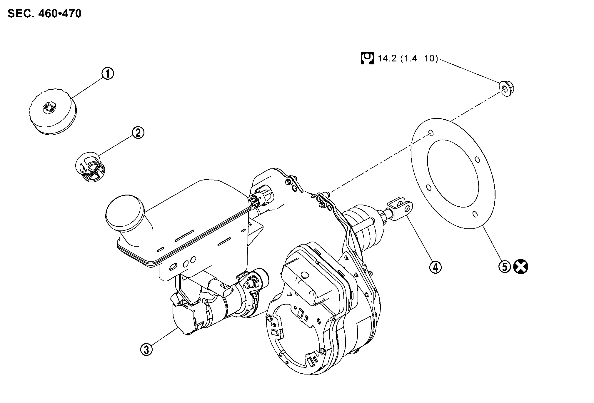
Exploded View
 |
Reservoir cap |  |
Oil strainer |  |
Electrically-driven intelligent brake unit |
 |
Clevis |  |
Gasket | ||
 |
: N┬Ęm (kg-m, ft-lb) | ||||
 |
: Always replace after every disassembly. | ||||
Removal & Installation
REMOVAL
CAUTION:
-
While electrically-driven intelligent brake unit
is removed, hold part  with hand.
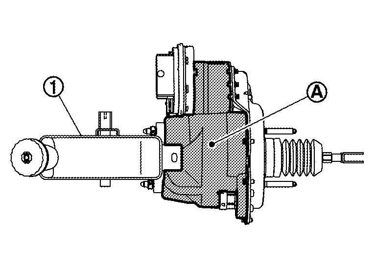
-
Never disassemble electrically-driven intelligent brake unit.
-
Never spill or splash brake fluid on painted surfaces. Brake fluid may seriously damage paint. Wipe it off immediately and wash with water if it gets on a painted surface. For brake component parts, never wash them with water.
-
Never depress brake pedal during removal and installation of brake hose because brake fluid may scatter.
Perform inspection before removal. Refer to Inspection.
Power switch OFF and disconnect CONSULT from DDL2 diagnosis connector.
Check that room lamps are turned OFF after closing all doors including back door, and then wait for 3 minutes or more at out side of Nissan Ariya vehicle.
Remove battery tray 1. Refer to Removal and Installation.
Drain brake fluid. Refer to Draining.
Disconnect the harness connectors from the engine control module (ECM).
Separate the brake tubes from the master cylinder part of the electrically-driven intelligent brake unit using a flare nut wrench.
Disconnect the harness connector from the brake fluid level switch.
Disconnect the harness connector from the electrically-driven intelligent brake unit.
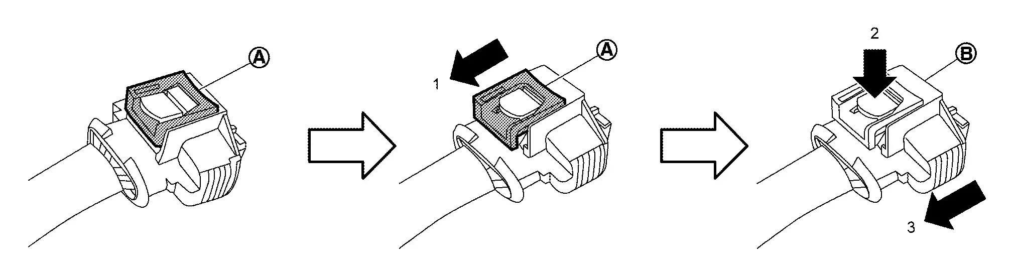
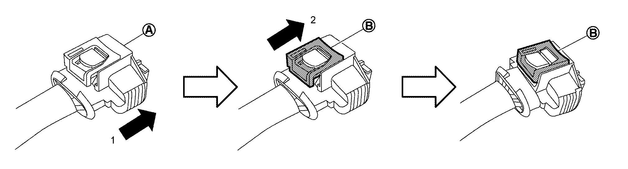
Disconnect the harness connector from the stroke sensor as follows:Slide the connector lock (A) away (1) from the terminal side of the connector. While pressing the connector lock release button (2), pull the connector (B) away (3) from the stroke sensor part of the electrically-driven intelligent brake unit.
Separate the harness retainer from the reservoir tank.
CAUTION:
Hold electrically-driven intelligent brake unit to prevent it from dropping.
Remove the driver knee air bag module. Refer to Removal and Installation.
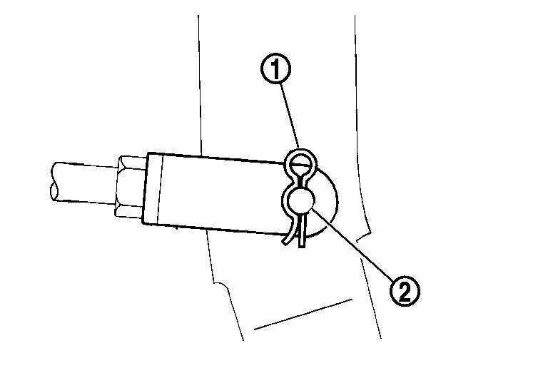
Remove the snap pin (1) and the clevis pin (2) from the clevis.
Remove the nuts and the bracket from the brake pedal. Refer to Removal and Installation.
Remove the nuts that retain the electrically-driven intelligent brake unit to the brake pedal. Refer to Exploded View.
Remove the electrically-driven intelligent brake unit.
CAUTION:
Never deform the brake tube when removing electrically-driven intelligent brake unit.
Remove the gasket from the electrically-driven intelligent brake unit.
INSTALLATION
CAUTION:
When installing electrically-driven intelligent brake unit, never deform brake tube.
-
If electrically-driven intelligent brake unit is dropped or impacted, replace electrically-driven intelligent brake unit assembly.
-
When installing, hold part
of electrically-driven intelligent brake unit. -
Never apply grease or lubricant to the parts that contact with brake fluid and rubber parts.
-
Never spill or splash brake fluid on painted surfaces. Brake fluid may seriously damage paint. Wipe it off immediately and wash with water if it gets on a painted surface. For brake component parts, never wash them with water.
-
Never depress brake pedal during removal and installation of brake hose because brake fluid may scatter.
Note the following, and install in the reverse order of removal.
-
Never crush threads of stud bolts of the electrically-driven intelligent brake unit. When installing diagonally, the dash panel may damage the threads.
-
Never deform brake tube when installing electrically-driven intelligent brake unit.
-
Never reuse clevis pin.
-
Temporarily tighten the flare nut of brake tube by hand, and then tighten the flare nut to the specified tightening torque using flare nut torque wrench (commercial tool). Refer to Exploded View.
-
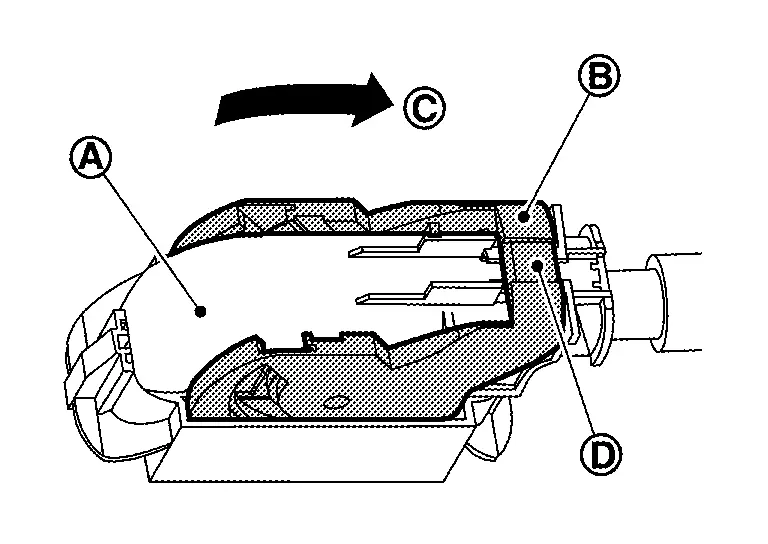
Connect the harness connector to the electrically-driven intelligent brake unit as follows:
-
With the connector lock unlocked, connect the harness connector (A) to the electrically-driven intelligent brake unit.
-
Move the lever part (B) in the direction (C) until the lever part locks.
-
Push in lock part (D) to lock the harness connector securely.
-
-
Connect the harness connector to the stroke sensor part of the electrically-driven intelligent brake unit as follows:
-
With connector lock unlocked, connect the harness connector (A) to the stroke sensor part of the electrically-driven intelligent brake unit in the direction (1).
-
Push the connector lock (B) in the direction (2) to lock the harness connector securely.
-
-
Connect the harness connector to the brake fluid level switch and lock the harness connector.
-
Perform air bleeding. Refer to Bleeding Brake System.
-
Check brake pedal for each item, adjust when there is deviation from the specified value. Refer to Inspection and Adjustment.
Inspection
INSPECTION BEFORE REMOVAL
Check brake fluid level switch. Refer to Component Inspection.
INSPECTION AFTER REMOVAL
Check the following items, and replace the part if necessary.
-
Check for damage, deformation, interference with the other parts, and looseness of connection.
-
Check for fluid leakage from connection. Refer to Inspection.
CAUTION:
When fluid leakage is occurred, tighten each bolt to the specified torque. Replace parts if there is still leakage.
-
Measure the input rod length. Refer to Electrically-Driven Intelligent Brake Unit.
INSPECTION AFTER INSTALLATION
CAUTION:
Perform additional service when replacing electrically-driven intelligent brake unit. Refer to Work Procedure.
Other materials:
Admission Valve
Exploded View
Air duct bracket
Admission valve
gasket
Air duct hose
Air duct
Comply with the installation procedure when tightening. Refer to Removal and Installation.
To air duct. Refer to Exploded View.
To turbocharger. Refer to Exploded V ...
Manual Air Conditioning. Preparation. Preparation
Preparation
Special Service Tool
The actual shape of the tools may differ from those illustrated here.
Tool number
(TechMate No.)
Tool name Description
ŌĆāŌĆö
(NI-46534)
Trim Tool Set
Removing trim components
Commercial Service Tools
Tool name Description
Power ...
P2614 Intake Camshaft Position Sensor
DTC Description
DTC DETECTION LOGIC DTC
CONSULT screen terms
(Trouble diagnosis content)
DTC detection condition
P2614
00
A camshaft posi signal B1
(Camshaft A Position Signal Output Circuit/Open Bank 1 )
A
Diagnosis condition
Engine running at idle
Signal (termin ...