Nissan Rogue (T33) 2021-Present Service Manual: Removal and Installation :: Rear Seat
Exploded View
Exploded View (Removal)
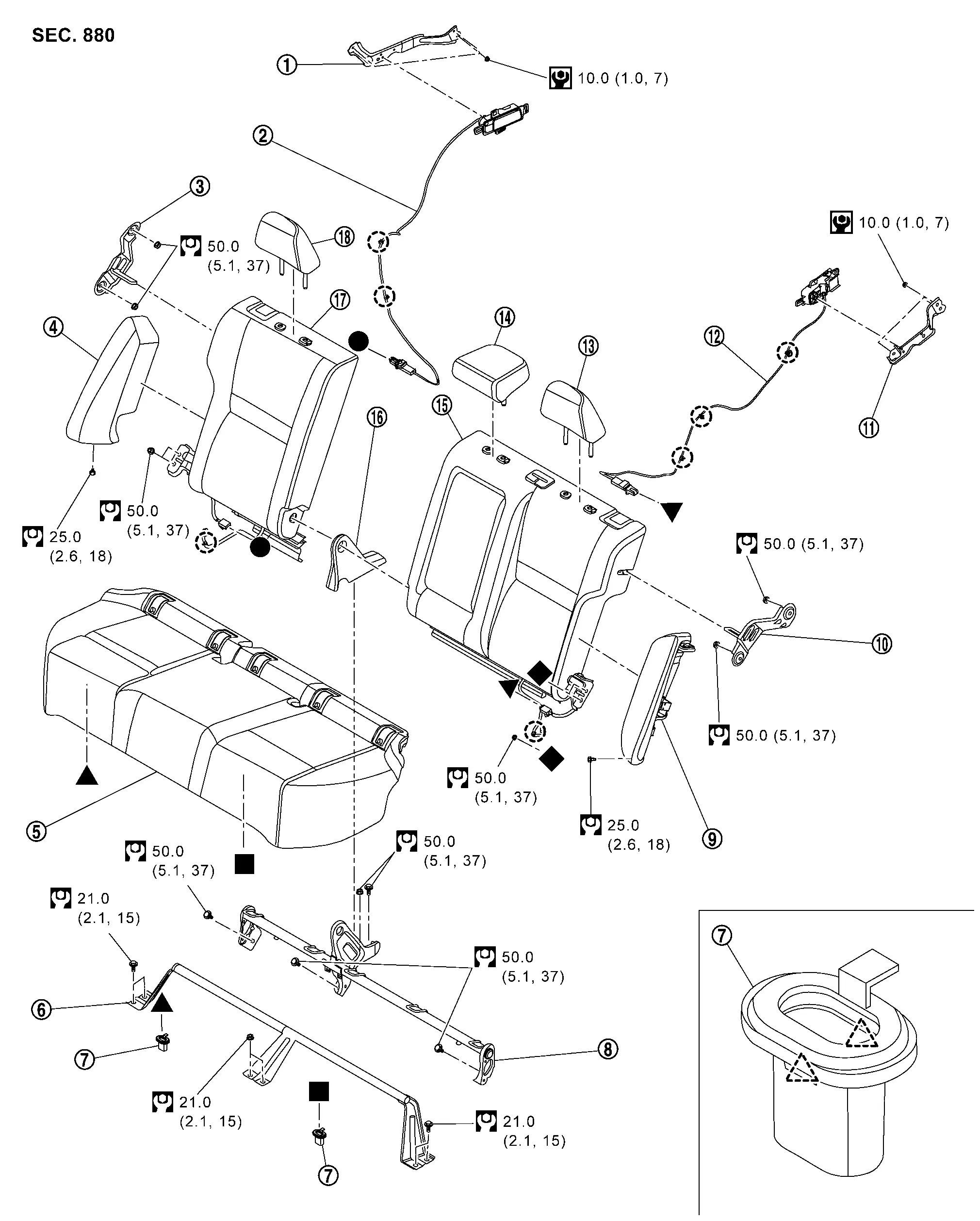
| 1. | Seatback remote release lever bracket RH* | 2. | Seatback remote release lever assembly RH* | 3. | Seatback striker RH |
| 4. | Seatback bolster RH | 5. | Seat cushion assembly | 6. | Seat cushion cross member |
| 7. | Seat cushion hook | 8. | Center hinge | 9. | Seatback bolster LH |
| 10. | Seatback striker LH | 11. | Seatback remote release lever bracket LH* | 12. | Seatback remote release lever assembly LH* |
| 13. | Headrest LH | 14. | Center headrest | 15. | Seatback assembly LH |
| 16. | Center hinge cover | 17. | Seatback assembly RH | 18. | Headrest RH |
 |
: Clip | ||||
 |
: Pawl | ||||
 |
: N·m (kg-m, in-lb) | ||||
 |
: N·m (kg-m, ft-lb) | ||||
â—Ź,â–˛,â– ,â–Ľ,â—† : Indicates that the part is connected at points with same symbol in actual Nissan Ariya vehicle.
* : With rear seatback release lever models
Exploded View (Disassembly)
SEAT CUSHION
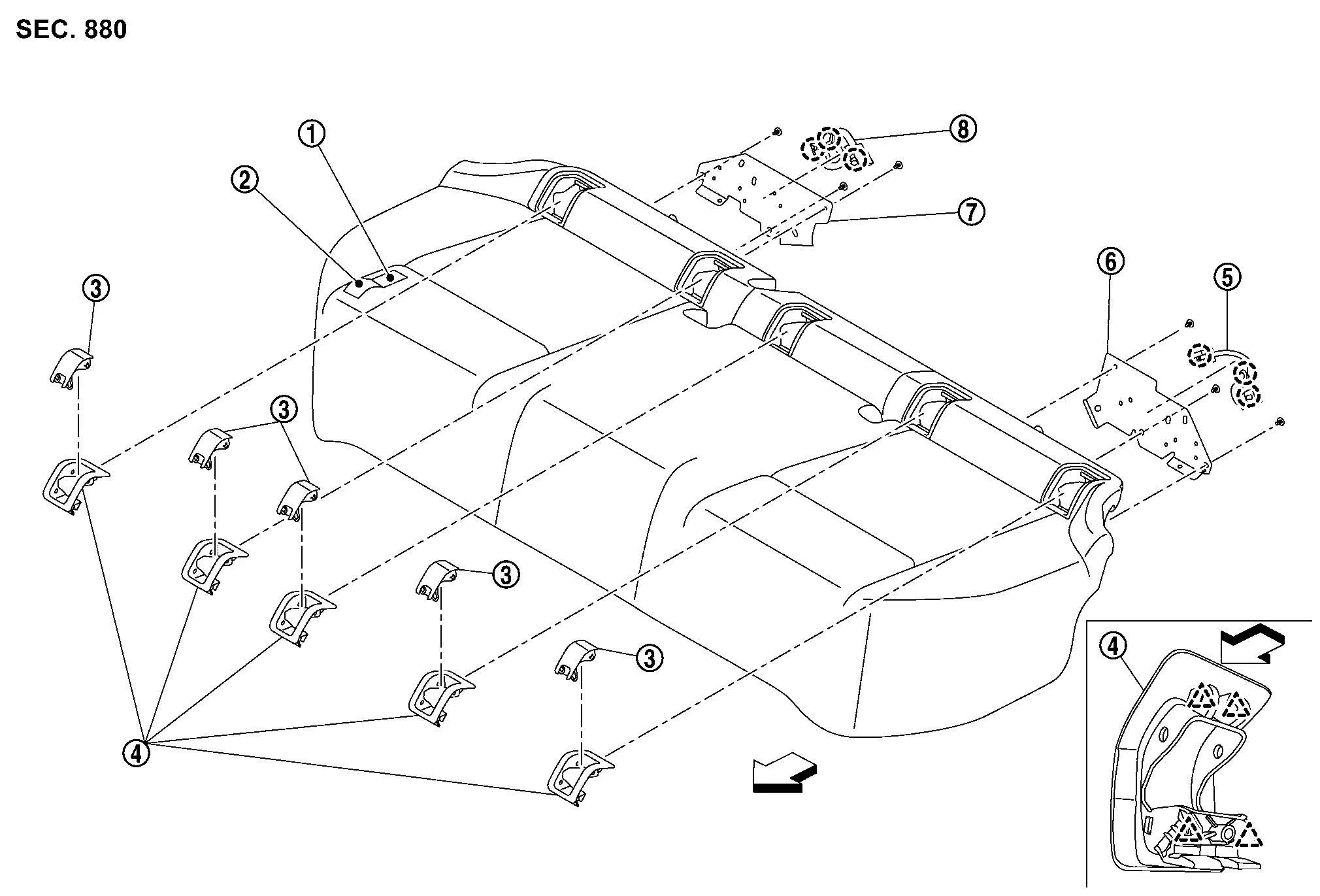
| 1. | Seat cushion pad | 2. | Seat cushion trim | 3. | ISO FIX bracket cover |
| 4. | ISO FIX bracket finisher | 5. | Seat cushion harness LH | 6. | Seat cushion harness bracket LH |
| 7. | Seat cushion harness bracket RH | 8. | Seat cushion harness RH | — | — |
|
: Clip | ||||
|
: Pawl | ||||
| : Nissan Ariya Vehicle front | |||||
SEATBACK LH
| 1. | Seatback release cable*1 | 2. | Armrest assembly | 3. | Bush |
| 4. | Seatback release cable*2 | 5. | Seatback trim LH | 6. | Seatback pad LH |
| 7. | Seatback frame LH | 8. | Seatback release lever | 9. | Seatback release lever finisher |
| 10. | Headrest holder (lock) | 11. | Headrest holder (free) | 12. | Center seat belt finisher |
|
: Clip | ||||
|
: Pawl | ||||
| : Nissan Ariya Vehicle front | |||||
â—Ź,â–˛ : Indicates that the part is connected at points with same symbol in actual vehicle.
*1 : Without rear seatback release lever models.
*2 : With rear seatback release lever models.
SEATBACK RH
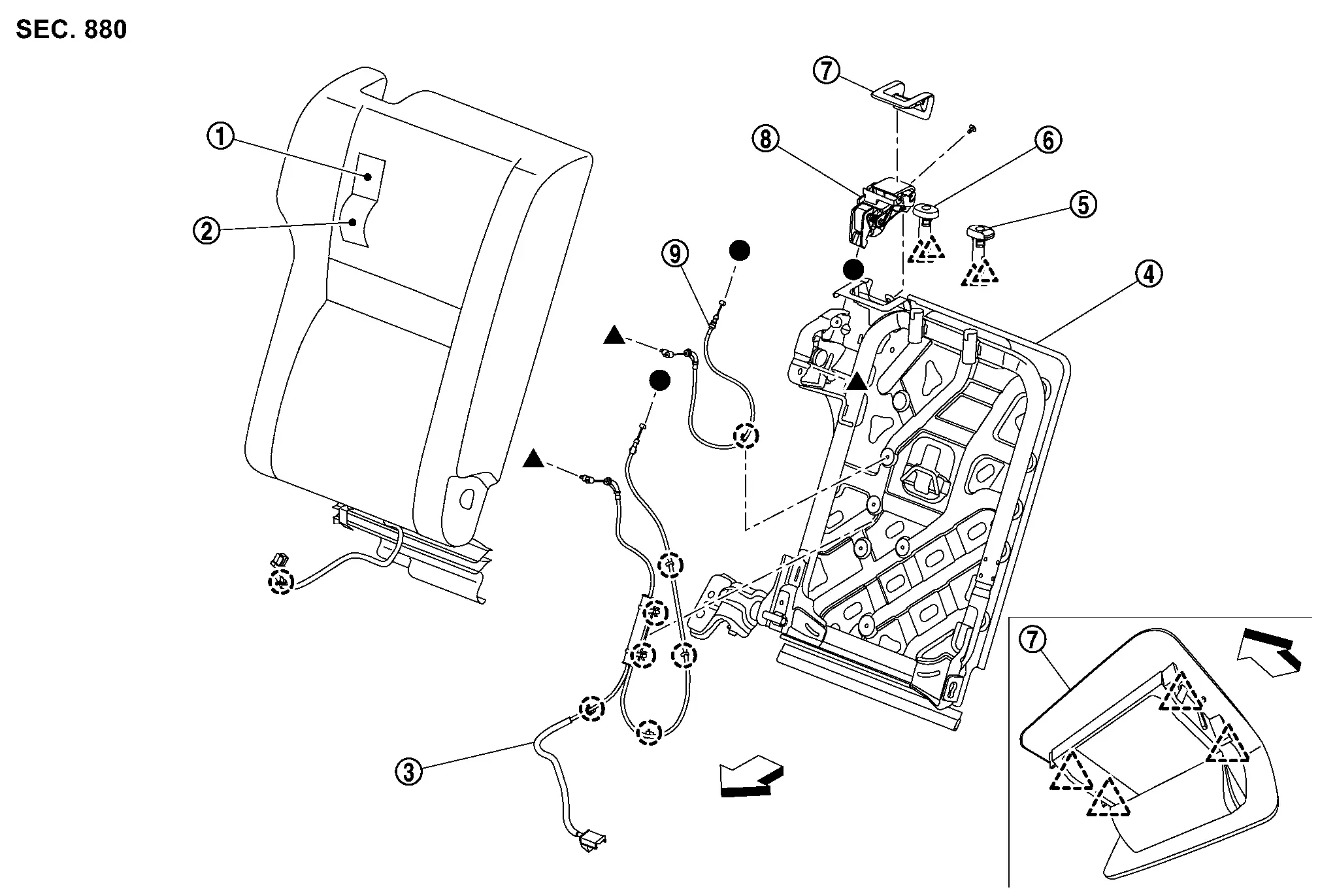
| 1. | Seatback pad RH | 2. | Seatback trim RH | 3. | Seatback release cable*1 |
| 4. | Seatback frame RH | 5. | Headrest holder (lock) | 6. | Headrest holder (free) |
| 7. | Seatback release lever finisher | 8. | Seatback release lever | 9. | Seatback release cable*2 |
|
: Clip | ||||
|
: Pawl | ||||
| : Nissan Ariya Vehicle front | |||||
â—Ź,â–˛ : Indicates that the part is connected at points with same symbol in actual vehicle.
*1 : With rear seatback release lever models.
*2 : Without rear seatback release lever models.
Removal and Installation
WARNING:
-
Before servicing the SRS, place the ignition switch OFF, disconnect both battery terminals and wait at least 3 minutes.
-
Always work from the side of the rear seat bolster.
-
Do not use air tools or electric tools for servicing the rear seat bolster.
-
Always place the rear seat bolster with the pad side facing upward.
-
Do not cause impact to the rear side air bag module by dropping, etc. Repace the rear seat bolster if it has been dropped or sustained an impact.
-
Do not allow oil, grease, detergent or water to come in contact with the rear side air bag module.
Removal and Installation
CAUTION:
-
When removing and installing, use shop cloth to protect parts and Nissan Ariya vehicle from damage.
-
When removing or installing, 2 or more worker required because there are big and heavy components.
REMOVAL
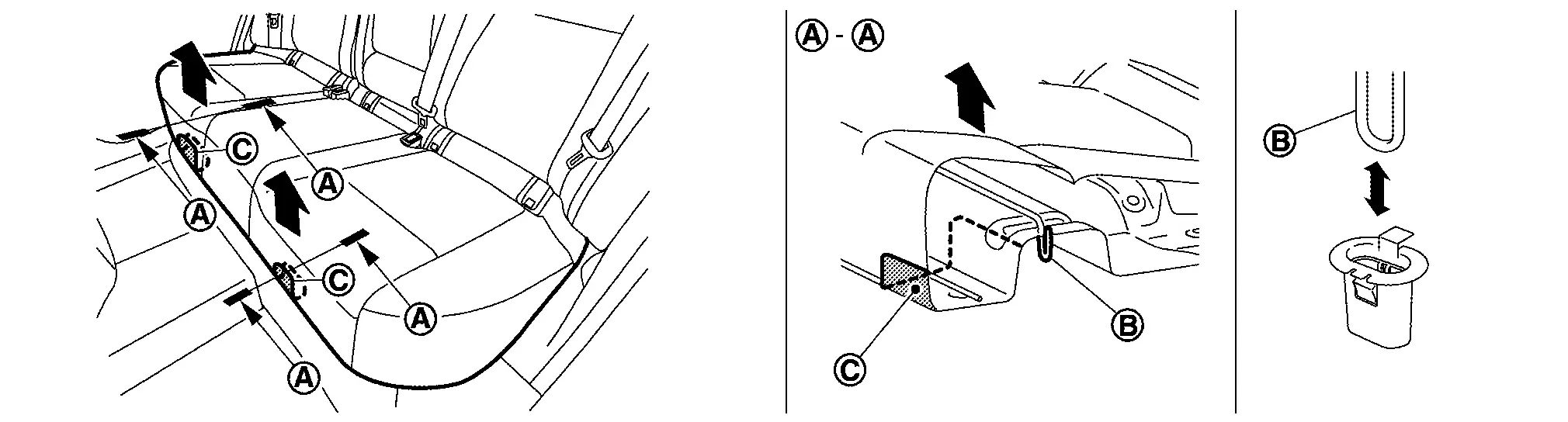
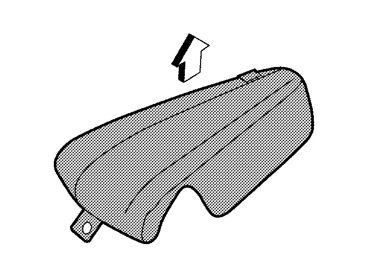
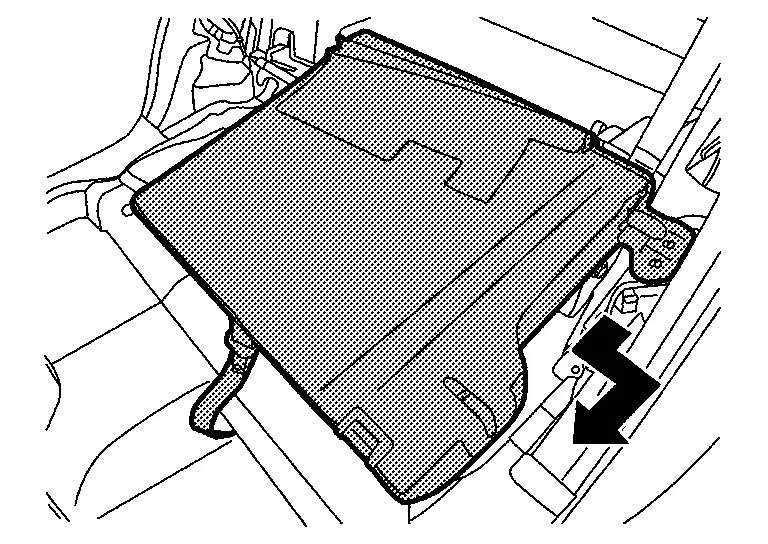
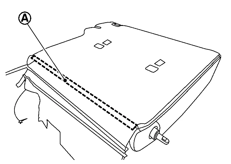
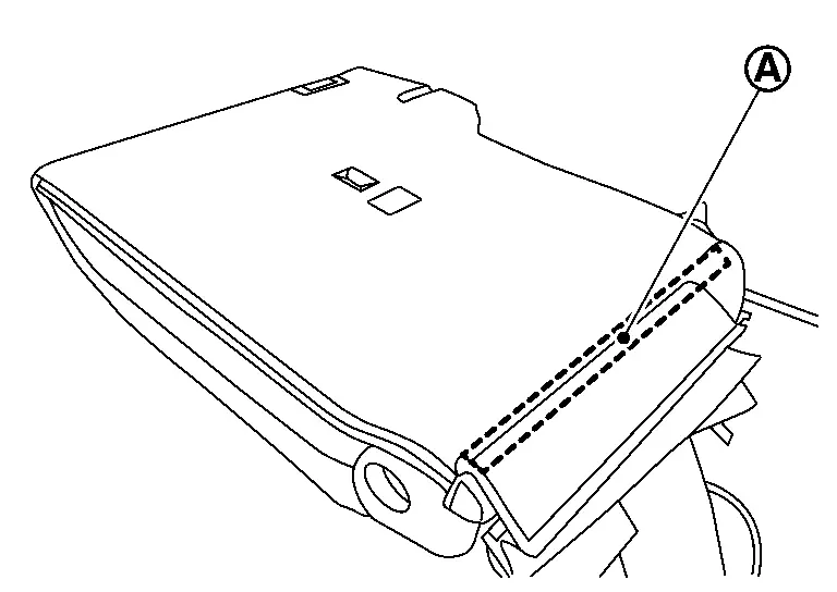
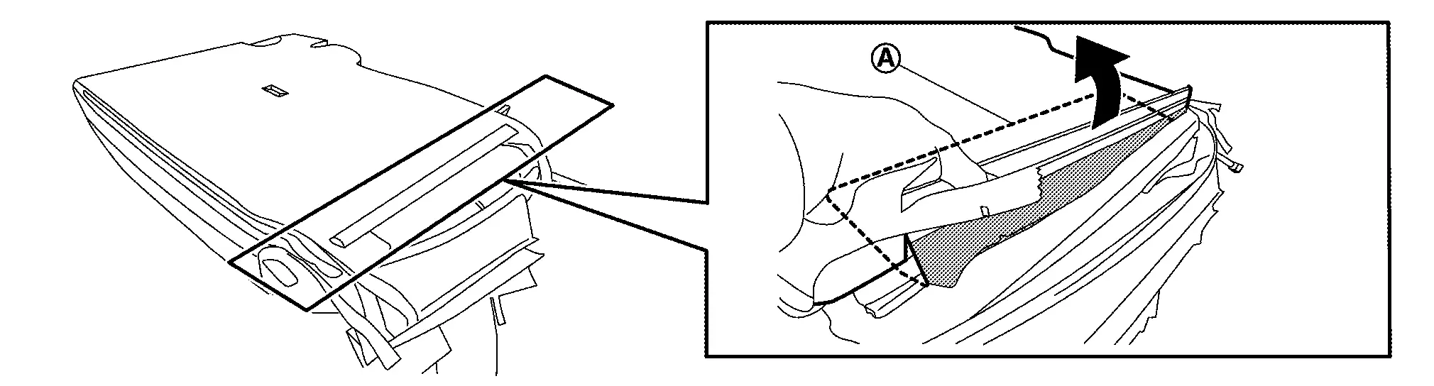
Remove seat cushion.lift up seat cushion as a close position (C) of engaging portion (B) and disengage seat cushion hooks.
 .
.
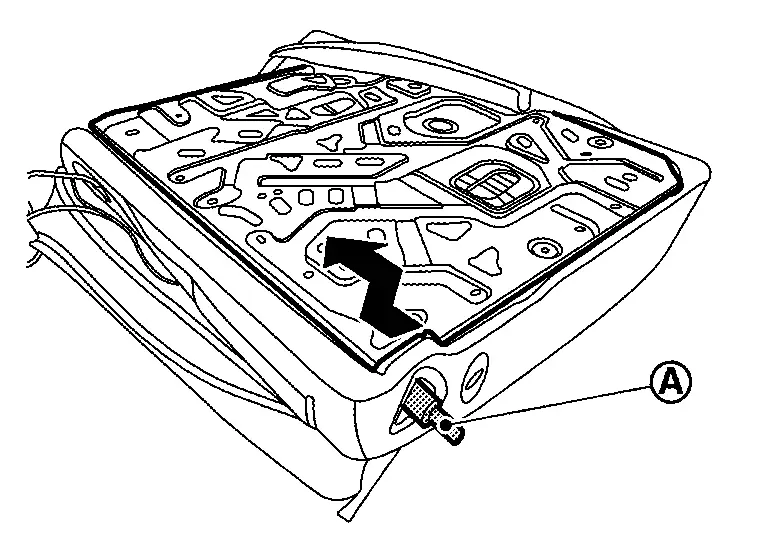
Remove seat cushion cross member.Remove rear kicking plate. Refer to Removal and Installation. Remove mounting nuts and bolts (A), and then remove seat cushion cross member.
Disengage fixing pawls according to numerical order 1, 2 indicated by arrows as shown in figure, and then remove seat cushion hooks.
|
: Pawl |
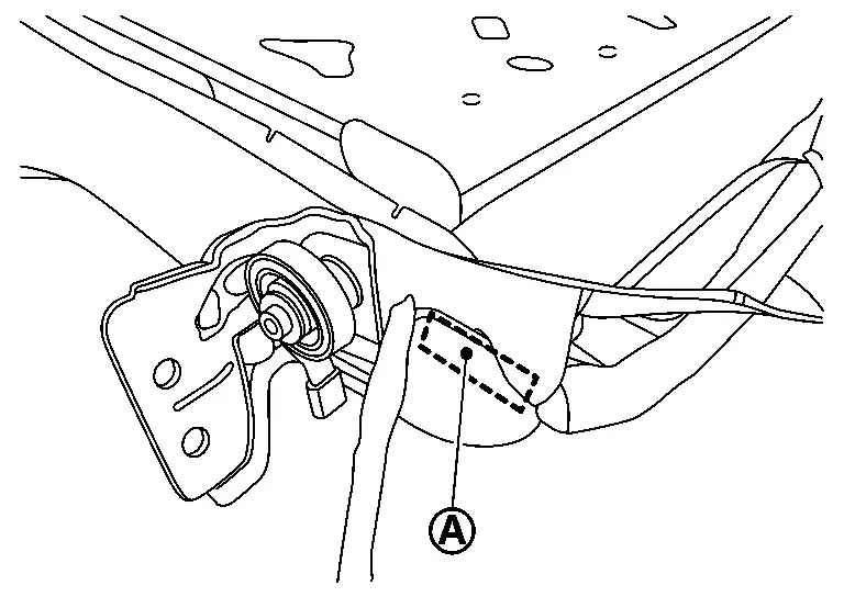
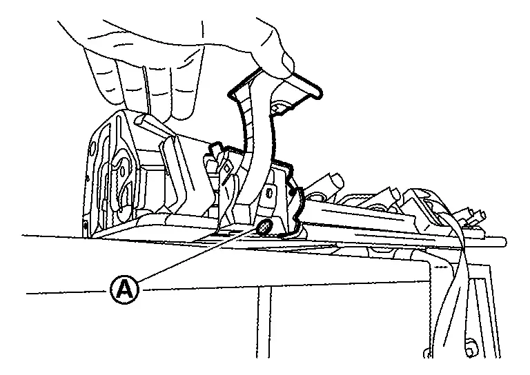
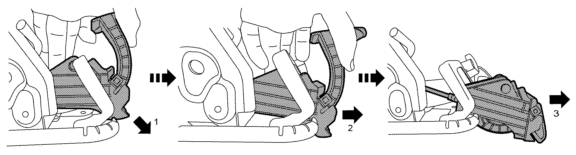
Remove seatback bolster RH.Remove seatback bolster RH mounting bolt (A).
CAUTION:
-
Seatback bolster has included rear side air bag module.
-
Never disassemble seatback bolster trim, pad and rear side air bag module. If need to replace them, replace by assembly.
-
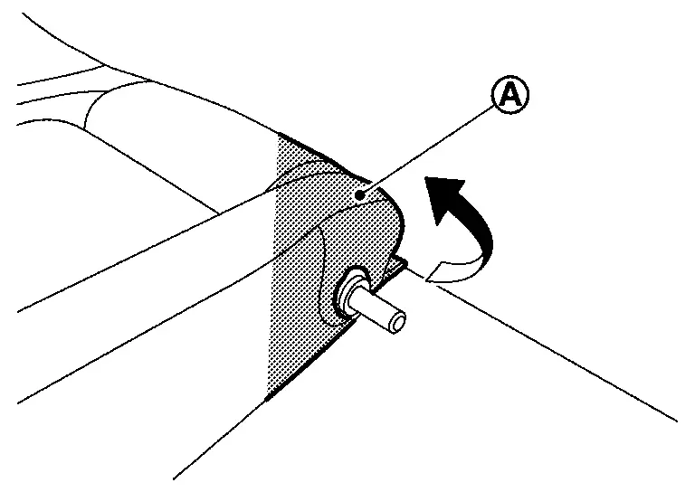
To prevent accidental explosion, always place the rear side air bag module with deploying direction facing upward as shown in figure.

: Deploying direction -
To prevent damage to the parts, never impact to the seatback bolster.
-
Replace seatback bolster if it is dropped or sustains an impact.
-
To prevent accidental explosion, never expose seatback bolster to temperature of more than 90°C (194°F).
-
To prevent damage to the parts, never allow oil, grease, detergent, or water to come in contact with seatback bolster.
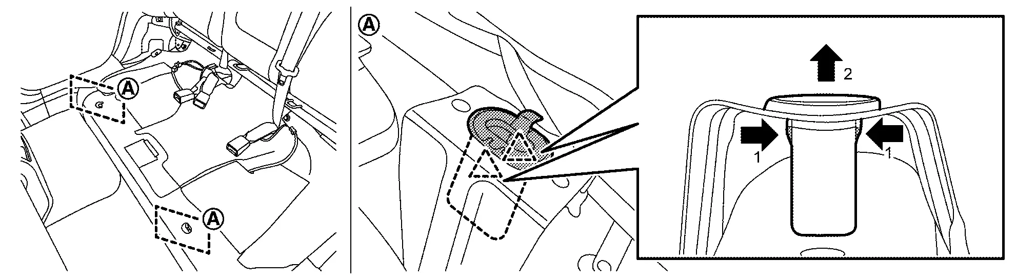
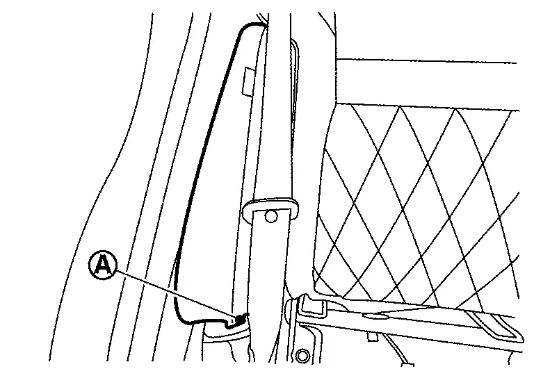
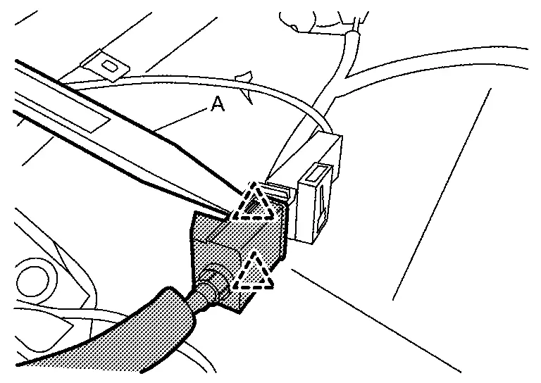
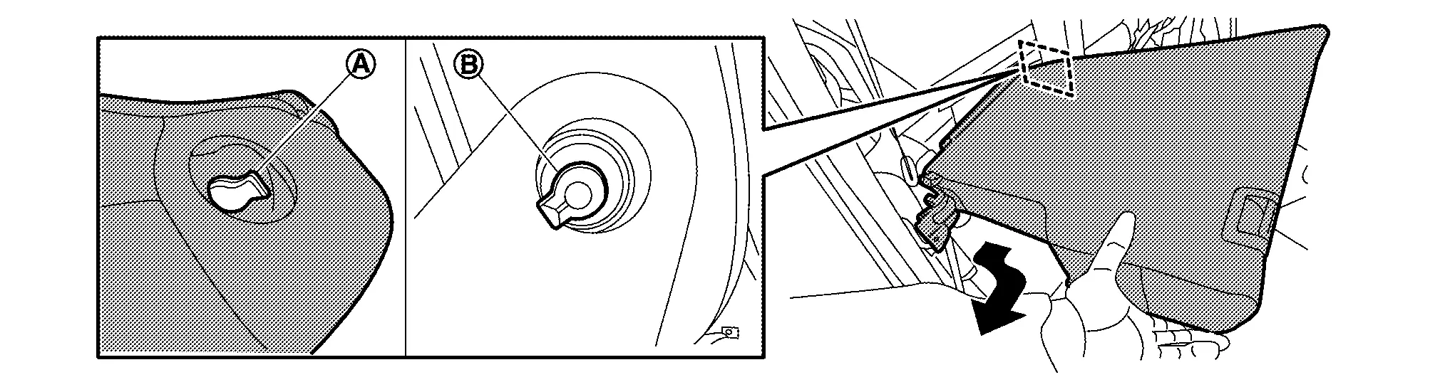
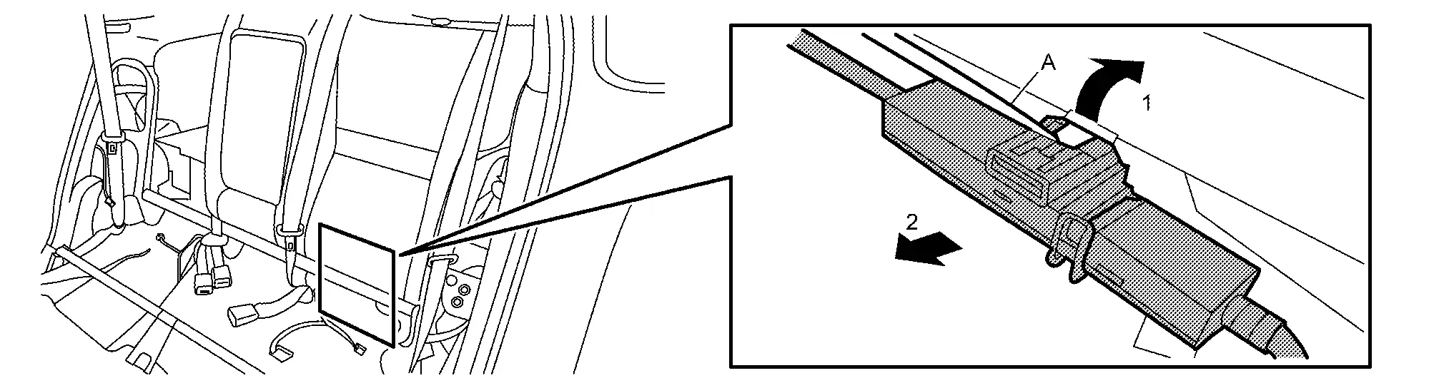
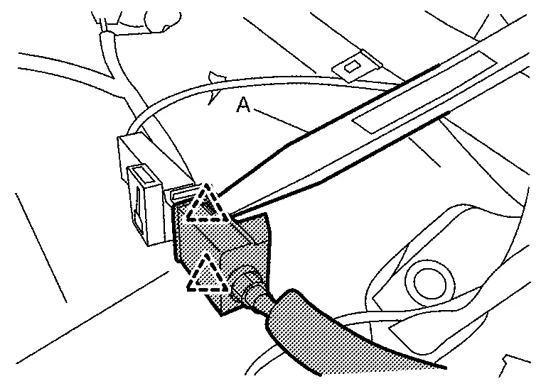
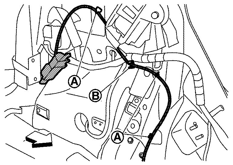
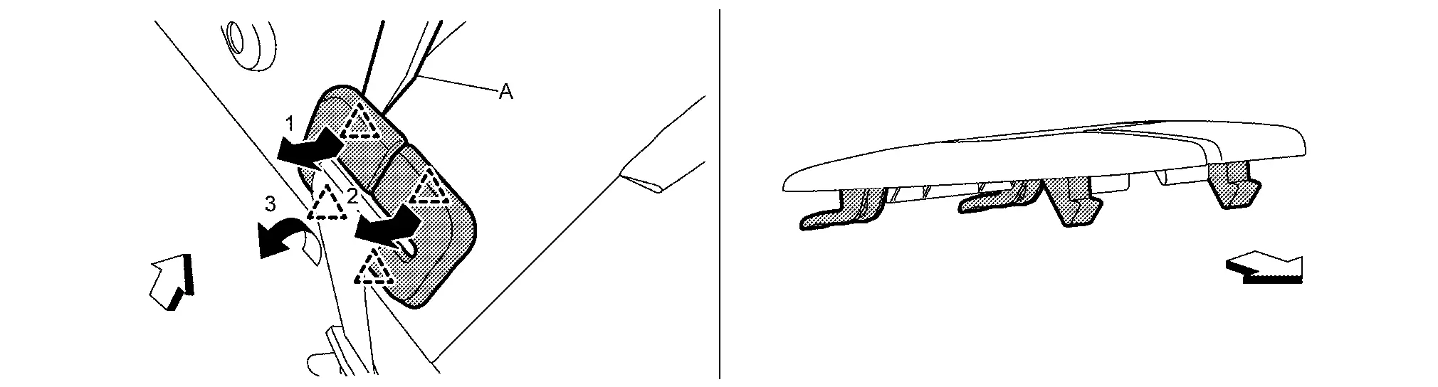
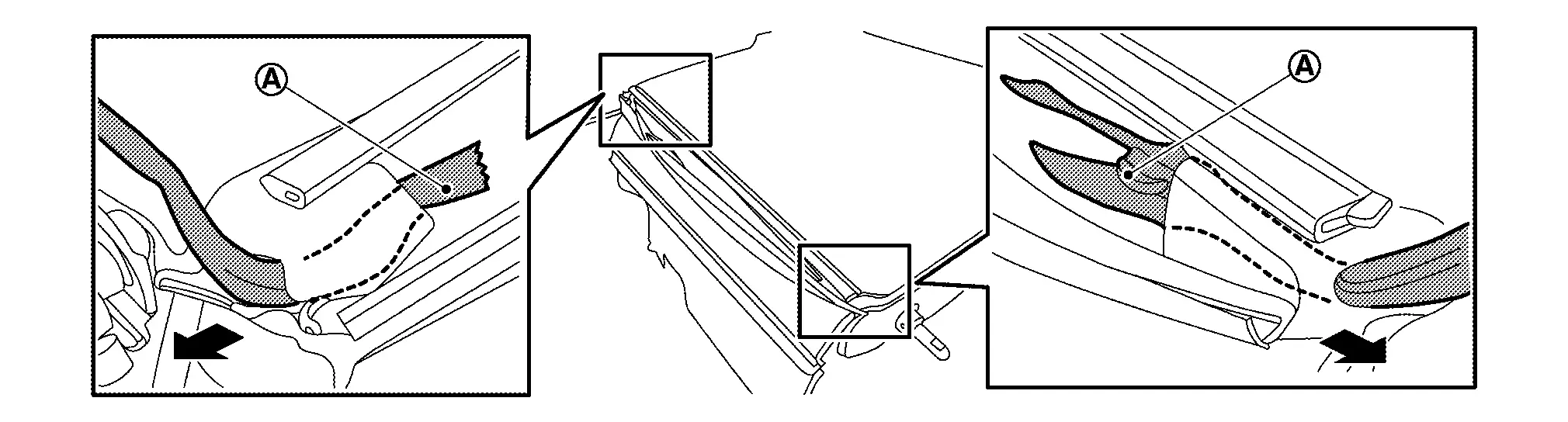
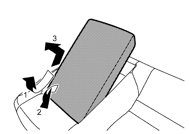
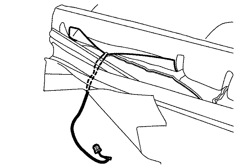
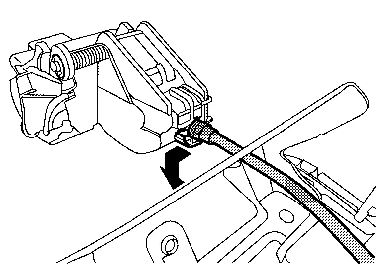
Remove seatback RH.Remove headrest. Remove front luggage floor cover (with ProPILOT Assist 2.1). Refer to Exploded View. Pull up seatback, and then lock seatback striker RH. Disengage fixing portion by arrow direction according to numerical order 1, 2 using a remover tool (A), and then remove seatback release cable from center hinge (with rear seatback release lever models).
|
: Pawl |
Remove seatback bolster LH.Remove seatback bolster LH mounting bolt .
CAUTION:
-
Seatback bolster has included rear side air bag module.
-
Never disassemble seatback bolster trim, pad and rear side air bag module. If need to replace them, replace by assembly.
-
To prevent accidental explosion, always place the rear side air bag module with deploying direction facing upward as shown in figure.
: Deploying direction -
To prevent damage to the parts, never impact to the seatback bolster.
-
Replace seatback bolster if it is dropped or sustains an impact.
-
To prevent accidental explosion, never expose seatback bolster to temperature of more than 90°C (194°F).
-
To prevent damage to the parts, never allow oil, grease, detergent, or water to come in contact with seatback bolster.
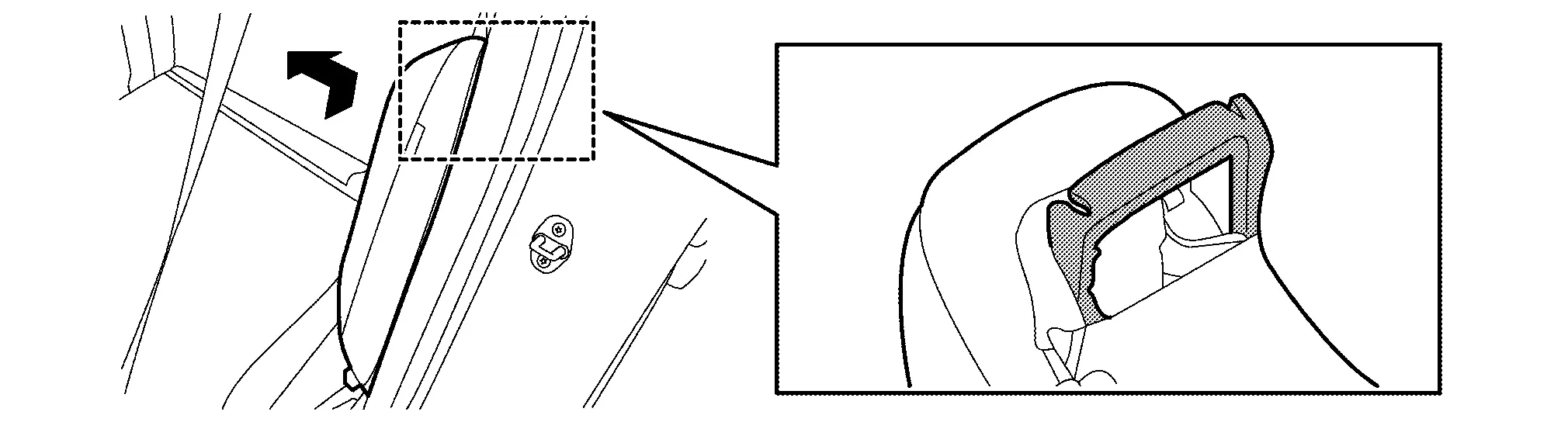
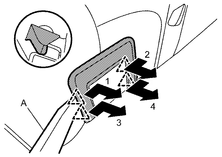
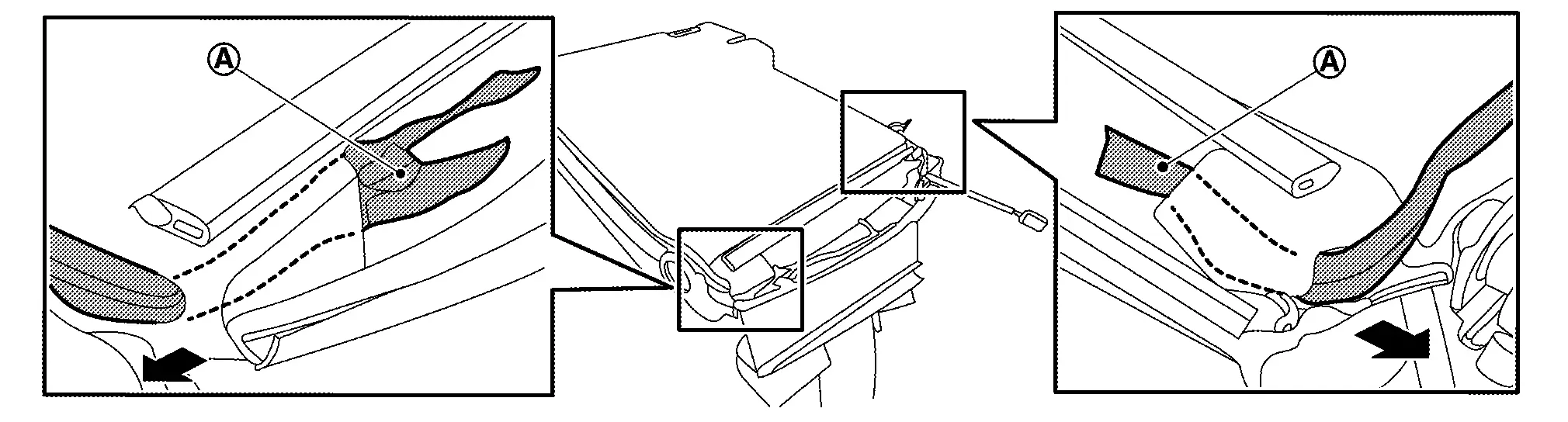
Remove seatback LH.Remove headrests. Remove front luggage floor cover (with ProPILOT Assist 2.1). Refer to Exploded View. Pull up seatback LH, and then lock seatback LH. Disengage fixing portion by arrow direction according to numerical order 1, 2 using a remover tool (A), and then remove seatback release cable from center hinge (with rear release lever models).
|
: Pawl |
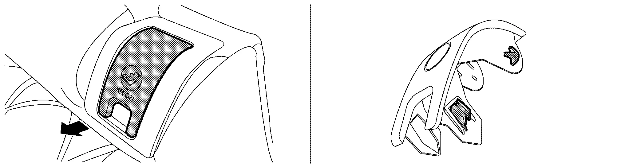
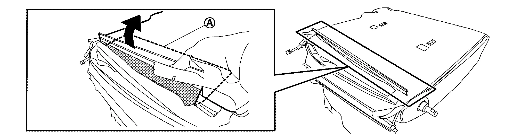
Put up center hinge cover, and then remove center hinge cover.
Remove mounting nuts and bolts, and then remove center hinge.
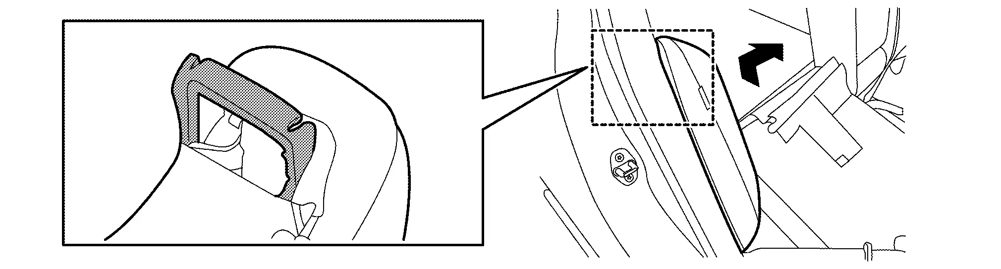
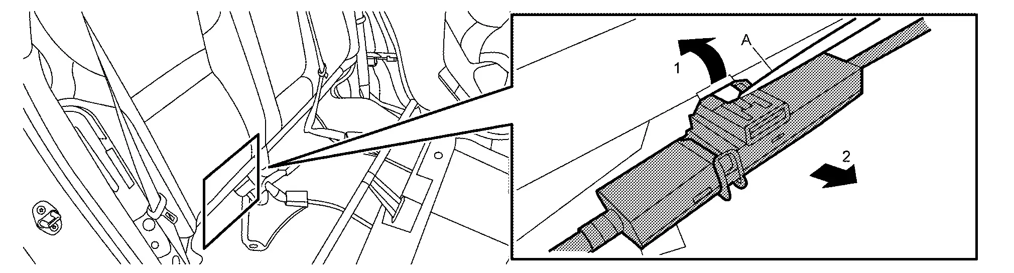
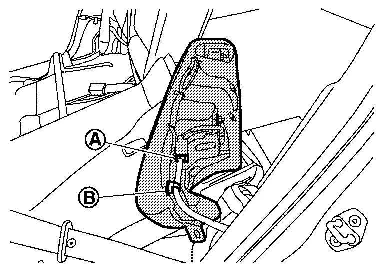
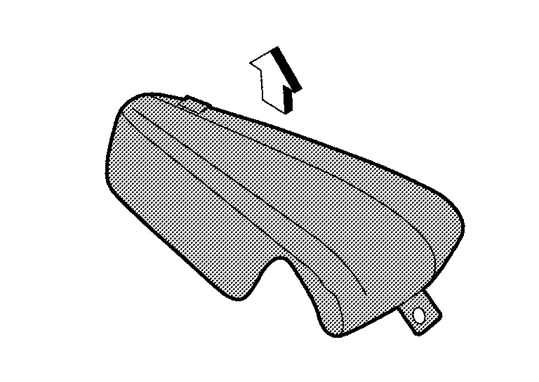
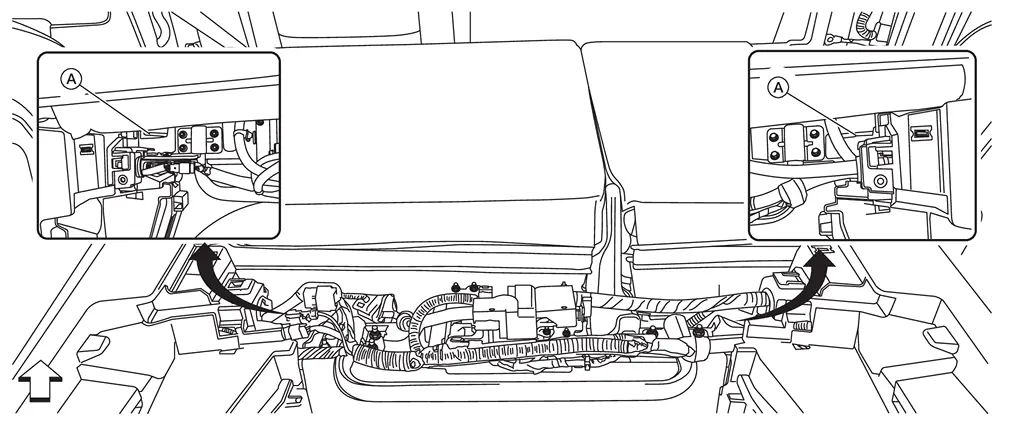
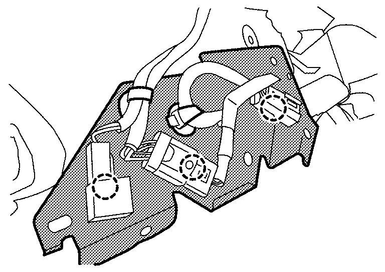
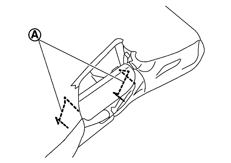
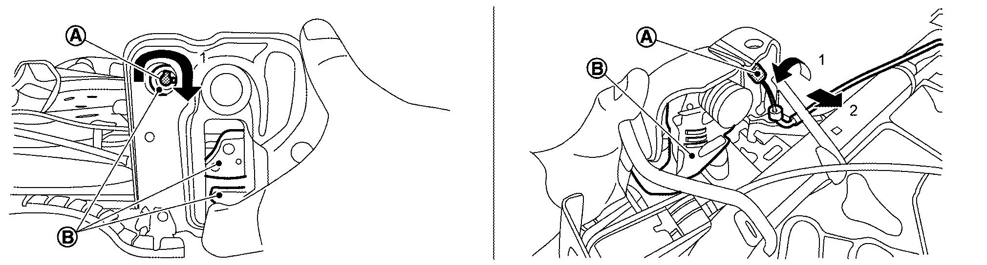
Remove seatback remote release lever assembly (with rear seatback release lever models).Remove luggage side lower finisher. Refer to Removal and Installation. Disengage fixing clips (A) and pull out holding clip(s) (B), and then remove seatback remote release lever assembly.
-
LH
: Nissan Ariya Vehicle front -
RH
: Nissan Ariya Vehicle front
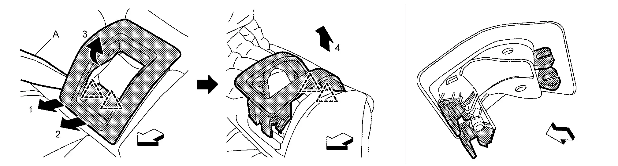
Remove mounting nuts, and then remove seatback remote release lever bracket.
Remove mounting nuts, and then remove seatback striker.
INSTALL
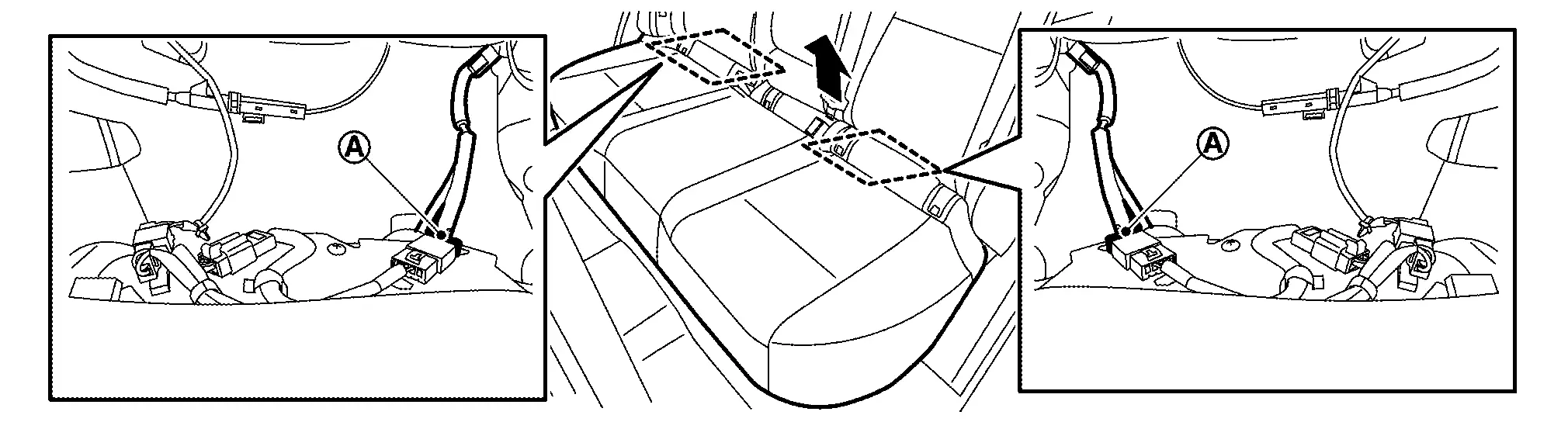
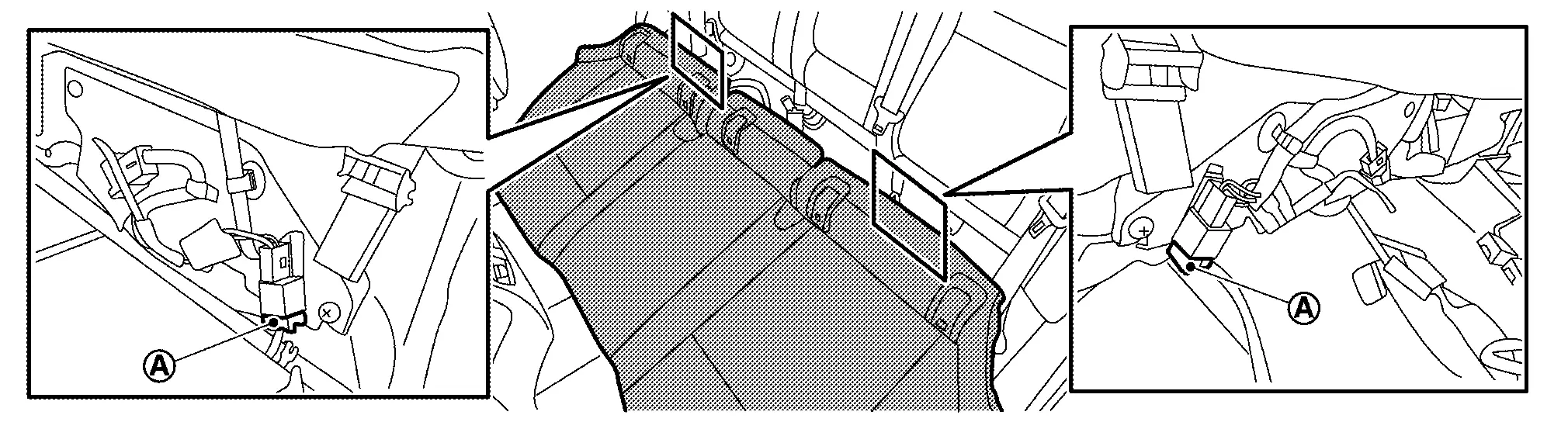
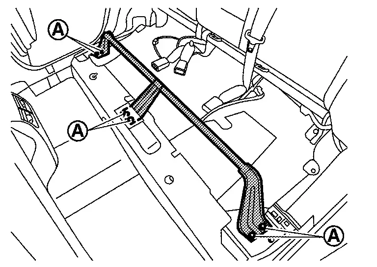
Note the following items, and then install in the reverse order of removal.
-
Always install harness, harness connector and cables in position.
-
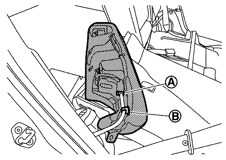
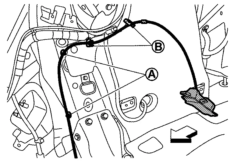
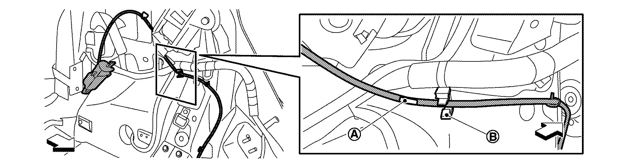
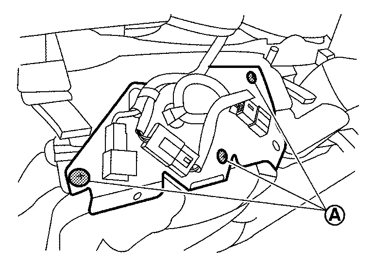
When installing seatback release lever LH, the matching mark tape (A) place to rear side of holding clip (B) as shown in figure.
: Nissan Ariya Vehicle front -
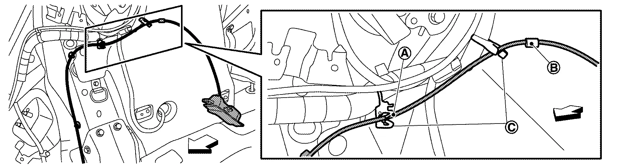
When installing seatback release lever RH, the felt tape (B) and matching mark tape (A) place to rear side of holding clips (C) as shown in figure.
: Nissan Ariya Vehicle front -
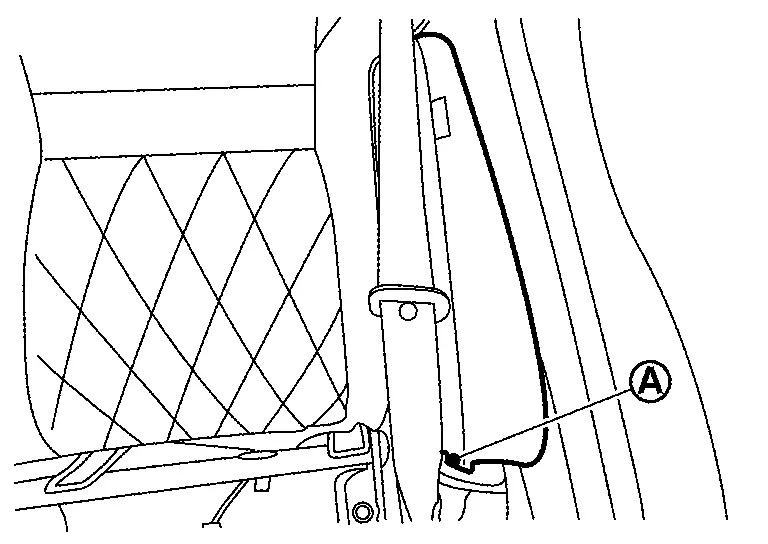
When installing seat cushion, push out rear seat belt buckles to seat cushion holes (A) from under the seat cushion.
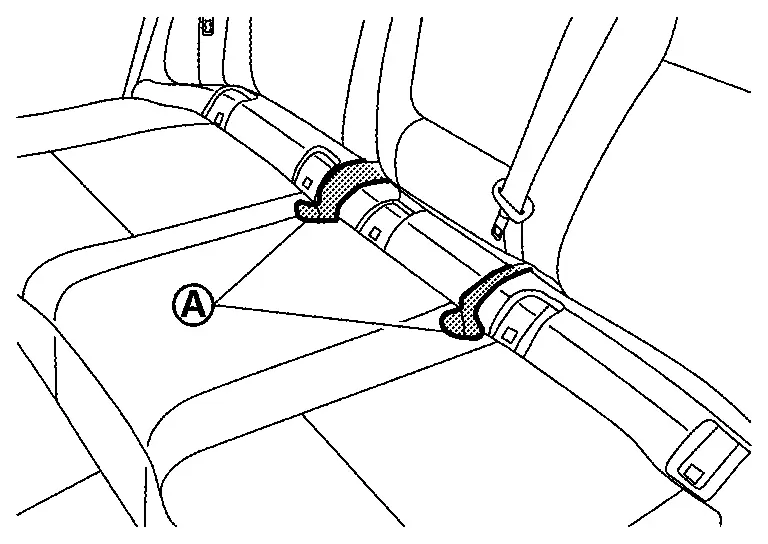
-
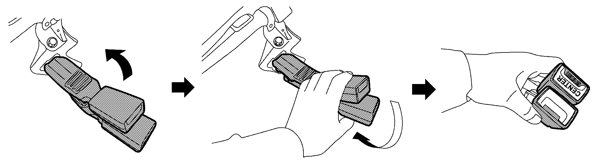
Before push up rear seat belt buckle RH and center, lift up and twice them as shown in figure, and then push up to seat cushion.
-
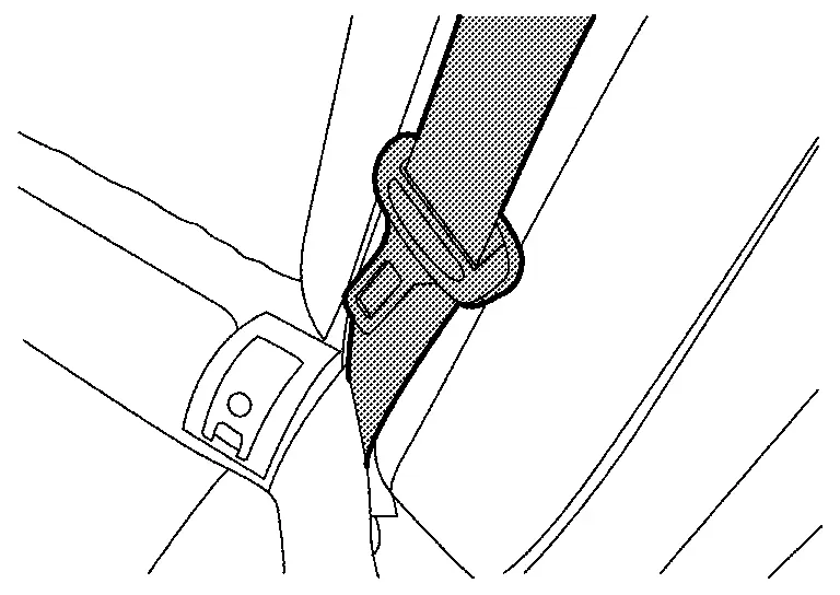
After installing seat cushion, check the seat belt retractor webbing direction are as shown in figure.
-
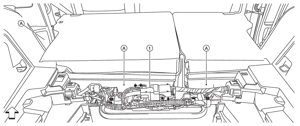
When installing the seatback for Nissan Ariya vehicles with ProPILOT Assist 2.1, ensure the seatback cloth (A) is between the seatback and the ADAS control unit 2 (1), not over it.

: Nissan Ariya Vehicle front -
When installing the seatback for vehicles with ProPILOT Assist 2.1, install seatback cloth fasteners (A) to the rear floor carpet.
: Nissan Ariya Vehicle front
Seat Cushion
Disassembly and Assembly
CAUTION:
When disassemble, always use the remover tool that is made by plastic to prevent damage to the parts.
DISASSEMBLY
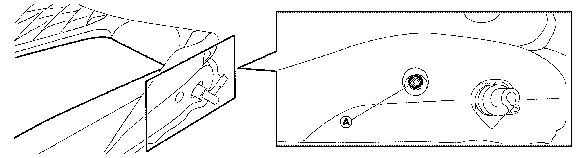
Disengage fixing portion by direction arrow as shown in figure, and then remove ISO FIX bracket cover.
Disengage fixing pawls according to numerical order 1ďż«4 using a remover tool (A), and then remove ISO FIX bracket finisher.
|
: Pawl |
| : Nissan Ariya Vehicle front |
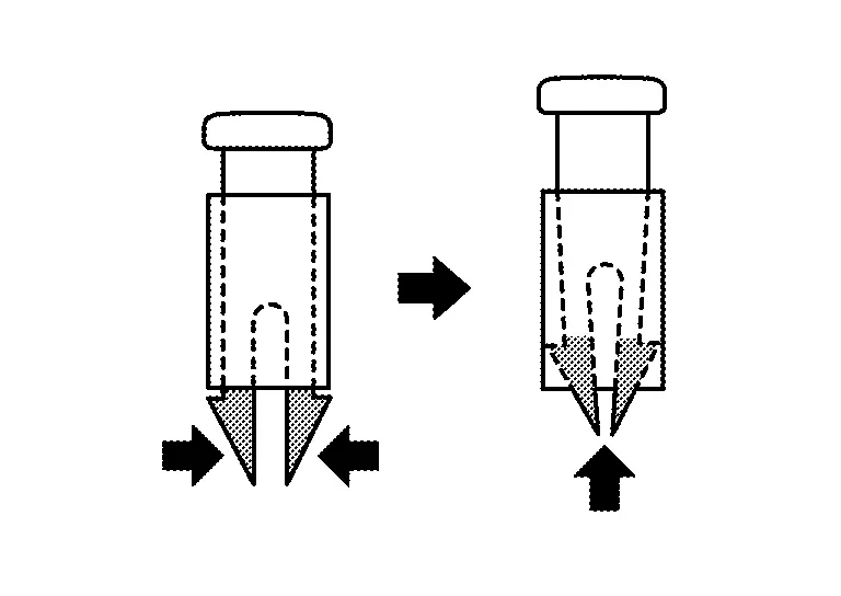
Remove fixing screws (A), and then remove seat cushion harness bracket from seat cushion pad.
Disengage harness and harness connector fixing clips, and then remove seat cushion harness bracket.
|
: Clip |
Disconnect harness connector, and then remove seat cushion harness.
Remove hog rings, and then separate seat cushion trim and pad.
CAUTION:
-
Before separating, check the installation position of hog rings.
-
Never disassemble heater unit and occupant detection sensor from seat cushion pad.
ASSEMBLY
Note the following items, and then assemble in the reverse order of disassembly.
CAUTION:
-
For hog ring that is removed or crimped unsuccessfully, fix it by using a new hog ring. (Never reuse hog ring.)
-
Always install the hog rings in position.
Seatback
Disassembly and Assembly
DISASSEMBLY
CAUTION:
When disassemble, always use a remover tool that is made of plastic to prevent damage to the parts.
Disengage fixing pawls according to numerical order 1ďż«3 indicated by arrows as shown in figure using a remover tool (A), and then remove center seat belt finisher.
|
: Pawl |
| : Nissan Ariya Vehicle front |
Disengage fixing pawls according to numerical order 1ďż«4 indicated by arrows as shown in figure using a remover tool (A), and then remove seatback release lever finisher.
|
: Pawl |
Disengage seatback trim fixing retainer (A).
-
LH
-
RH
Pull out end (A) of seatback trim fixing fastener.
-
LH
-
RH
Open seatback trim fixing fastener.
Pull out end (A) of seat back trim from between seatback frame and seatback pad as shown in figure.
-
LH
-
RH
Disengage seatback trim fixing dual lock fastener (A).
Remove armrest assembly (seatback LH).Roll up seatback trim (A) of supporting pin side .
Disengage seatback trim fixing retainers of seatback release lever side (A).
Disengage supporting pin (A) from seatback pad according to arrow direction as shown in figure.
Disengage fixing pawls while pinching pawls according to arrows as shown in figure, and then remove headrest holder.
CAUTION:
Before removing, check its orientation (front/rear, right/left).
Remove seatback frame from seatback pad.
Remove hog ring, and then separate seatback trim and pad.
CAUTION:
-
Before separate seatback trim and pad, pull out seatback heater harness from seatback trim.
-
Before removing hog rings, check the installation position of hog rings.
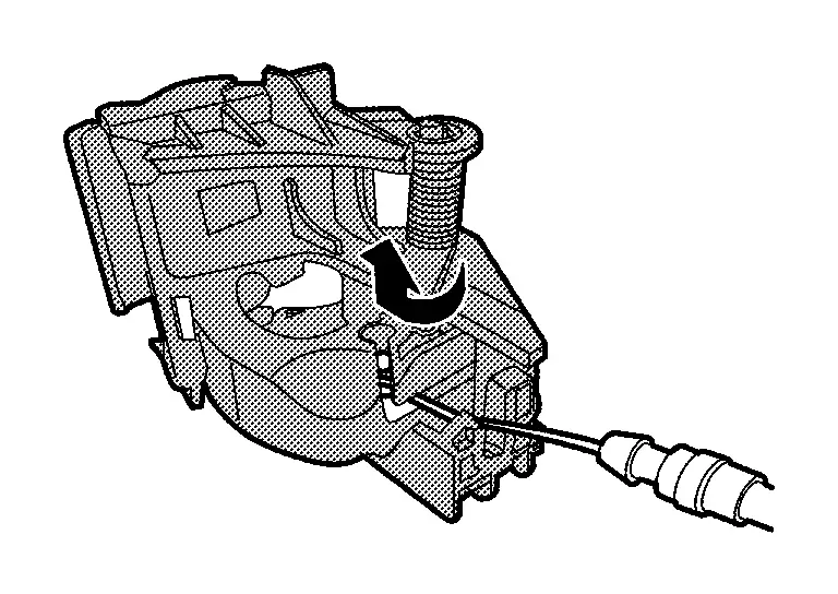
Remove seatback release lever and cable.Disengage seatback release cable fixing clips. Disengage the end of seatback release cable (A) from seatback frame latch (B) according to numerical order 1ďż«2 indicated by arrows while pulling latch as shown in figure.
ASSEMBLY
Note the following items, and then assemble in the reverse order of disassembly.
CAUTION:
-
For hog ring that is removed or crimped unsuccessfully, fix it by using a new hog ring. (Never reuse hog ring.)
-
Always install the hog rings in position.
Other materials:
Symptom Diagnosis. The Braking Force of Parking Brake Is Low
Description
The parking brake braking force is low and the vehicle moves backward when parked on an incline.
Diagnosis Procedure
REAPPLY THE PARKING BRAKE (1)
Pull the parking brake switch, and apply the parking brake.
Pull the parking brake switch 2 seconds ore mode.
Is the Nissan ...
2wd. Preparation. Preparation
Preparation
Special Service Tool
Tool number
(TechMate No.)
Tool name Description
KV40104000
( – )
Hub lock nut wrench
a: 85 mm (3.35 in)
b: 65 mm (2.56 in)
Removing and Installing wheel hub lock nut.
KV40107300
( – )
Boot band crimping tool
Installing bo ...
Usb Charge Port. Removal and Installation. Usb Charge Port
Usb Charge Port
Rear Usb Charge Port
Removal and Installation
REMOVALRemove console rear finisher. Refer to Removal and Installation.
Press the USB charge port fixing pawl from the back of the console rear finisher to remove the USB charge port.
: Pawl
INSTALLATIONNote the followin ...