
Nissan Rogue (T33) 2021-Present Service Manual: Removal and Installation :: Moonroof Motor Assembly
Exploded View
Refer to Exploded View.
Removal and Installation
REMOVAL
CAUTION:
-
Before removing moonroof motor, check that glass lid is fully closed.
-
After removing moonroof motor, never attempt to rotate moonroof motor assembly as a single unit.
Remove headlining to make work space. Refer to Removal and Installation.
Disconnect harness connector  from moonroof motor assembly, and then, remove moonroof motor assembly fixing screws
 .
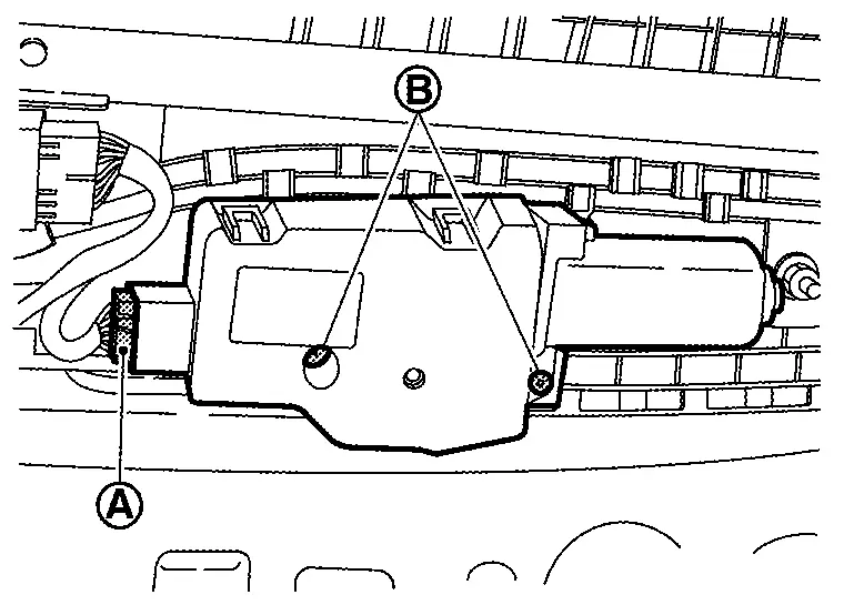
Remove moonroof motor assembly.
INSTALLATION
CAUTION:
-
Install moonroof motor assemblyand sunshade motor assembly in correct position without mistake.
-
Before installing the moonroof motor assembly, always place the link and wire of glass lid guide in the symmetrical and fully closed position.
Move the moonroof motor assembly laterally a little so that the gear is completely engaged into the wire on the moonroof unit assembly and mounting surface becomes parallel. Then secure the moonroof motor assembly with screws.
Connect harness connector.
Install headlining. Refer to Removal and Installation.
 NOTE:
After installation moonroof motor assembly, perform additional service. Refer to Description.
Other materials:
P02ee Fuel Injector
DTC Description
DTC DETECTION LOGIC DTC
CONSULT screen terms
(Trouble diagnosis content)
DTC detection condition
P02EE
00
Cylinder 1 injector
(Cylinder 1 Injector Circuit Range/Performance)
Diagnosis condition
Injector compensation control is operating
Signal
— ...
Dtc/circuit Diagnosis. Combination Switch Input Circuit
Diagnosis Procedure
CHECK INPUT CIRCUIT
Ignition switch OFF.
Disconnect combination switch connector.
Ignition switch ON.
Check voltage between combination switch harness connector and ground.
Switch signal + − Voltage
Combination switch
Connector Terminal
Input ...
U1327-54 Mac Key
DTC Description
DTC DETECTION LOGIC DTC No. CONSULT screen terms DTC detection condition
U1327
54
MAC key update
Diagnosis condition
—
Signal (terminal)
—
Threshold
MAC key is not written after chassis control module replacement.
Diagnosis delay time
— ...