Nissan Rogue (T33) 2021-Present Service Manual: Removal and Installation :: Intelligent Key Battery
Removal and Installation
-
Release the lock knob at the back of the Intelligent Key and remove the mechanical key.
-
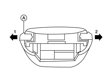
Using a suitable tool, release outer key bracket (A) in direction shown.
CAUTION:
-
Never touch the circuit board or battery terminal.
-
The Intelligant Key is water-resistant. However, if it does get wet, immediately wipe it dry.
-
-
Using a suitable tool, release pawls then remove outer key bracket (A).
CAUTION:
-
Never touch the circuit board or battery terminal.
-
The Intelligant Key is water-resistant. However, if it does get wet, immediately wipe it dry.
-
-
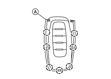
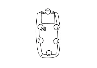
Using a suitable tool, release pawls, then separate upper part of Intelligent Key unit from lower part.
CAUTION:
-
Never touch the circuit board or battery terminal.
-
The Intelligant Key is water-resistant. However, if it does get wet, immediately wipe it dry.
-
-
Replace the battery with a new one.
Battery replacement :Coin-type lithium battery (CR2032) -
Align the tips of the upper and lower parts 1, and then push them together until it is securely closed 2.

CAUTION:
-
When replacing battery, keep dirt, grease, and other foreign materials off the electrode contact area.
-
After replacing the battery, check that all Intelligent Key functions work normally.
-
Other materials:
Vehicle Security System
System Description
SYSTEM DIAGRAM Component Function
Door switch
Door switch detects door open/close condition and then transmits door switch signal to BCM.
IPDM E/R
IPDM E/R operates horns with horn request signal received from BCM.
IPDM E/R operates headlamps with high be ...
Symptom Diagnosis. Door Does Not Lock/unlock with Intelligent Key (one Key)
Description
All doors do not lock/unlock using Intelligent Key button. (One Intelligent Key has the symptom, other keys operate normally.)NOTE:
Before starting diagnosis check that vehicle condition is
as shown in ŌĆ£Conditions of Nissan Ariya vehicleŌĆØ, and check each
symptom.
SYMPTOM TABLE ...
With Idle Start/stop. Removal and Installation. Sub Starter & Generator
Sub Starter & Generator
Exploded View
REMOVAL 1.
Collar
2.
Sub starter, generator and compressor bracket
3.
Sub starter & generator
4.
Sub starter & generator harness connector
5.
ŌĆ£BŌĆØ terminal
-
-
: Nissan Ariya Vehicle front
, , , : In ...