Nissan Rogue (T33) 2021-Present Service Manual: With Idle Start/stop :: Removal and Installation. Sub Starter & Generator
Sub Starter & Generator
Exploded View
REMOVAL
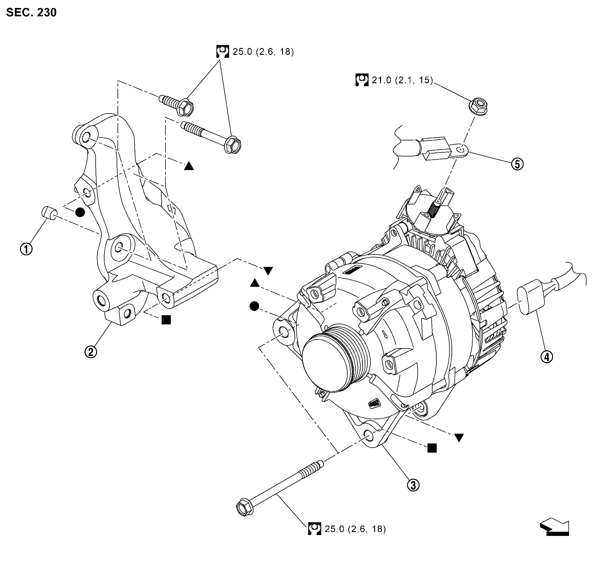
| 1. | Collar | 2. | Sub starter, generator and compressor bracket | 3. | Sub starter & generator |
| 4. | Sub starter & generator harness connector | 5. | “B” terminal | - | - |
| : Nissan Ariya Vehicle front | |||||
 , ,  , ,  , ,  : Indicates that the part is connected at points with same symbol in actual Nissan Ariya vehicle. : Indicates that the part is connected at points with same symbol in actual Nissan Ariya vehicle. |
|||||
Removal and Installation
REMOVAL
Disconnect battery cable from negative terminal. Refer to Precautions for Removing Battery Terminal.
Remove drive belt auto-tensioner. Refer to Removal and Installation.
Remove internal heat exchanger pipe. Refer to Removal and Installation.
Remove front grille cover. Refer to Exploded View.
Remove washer tank inlet. Refer to Exploded View.
Release reservoir tank hose clip.
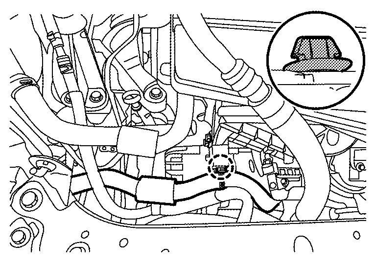
 |
: Clip |
Remove sub radiator reservoir tank mounting bolts, and then move sub radiator reservoir tank to create work space. Refer to Exploded View.
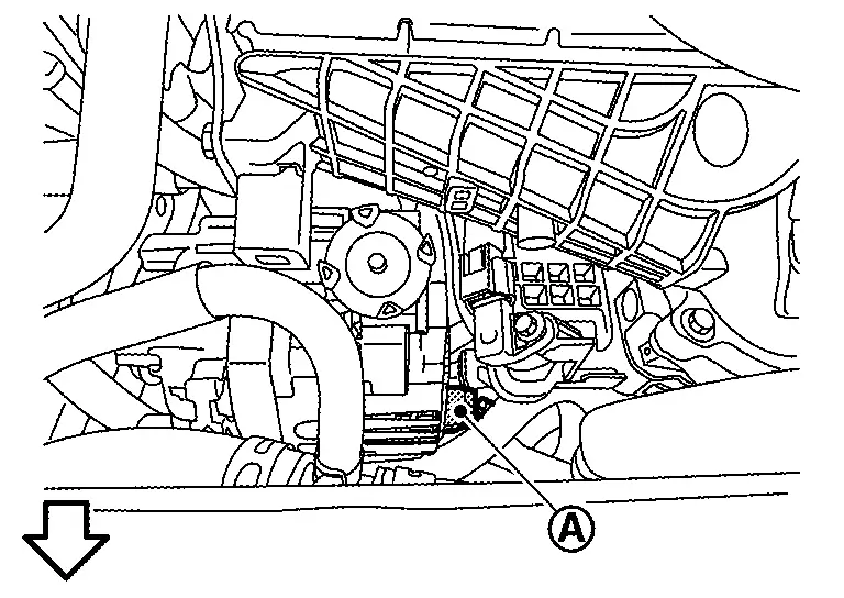
Remove ground harness mounting bolt (A), and then disconnect ground harness.
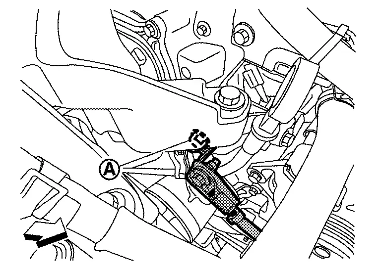
 |
:Front |
Remove oil level gauge.
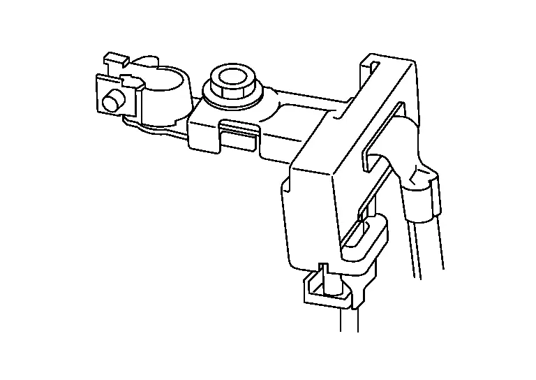
Remove “B” terminal mounting nut (A), and then disconnect “B” terminal (1).
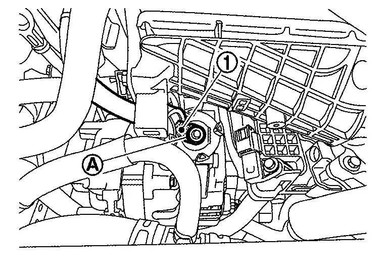
Disconnect sub starter and generator harness connector (A).
|
:Front |
Remove sub starter and generator bolts, and then remove generator.
CAUTION:
-
Be cafreful not to damage surrounding components.
-
Do not erase the sub starter & generator operation counter except when replacing sub starter & generator.
INSTALLATION
Installation is in the reverse order of removal.
CAUTION:
-
Temporarily tighten sub starter & generator bolts in order from the lower side to the upper side, and then tighten them in order from the upper side to the lower side.
For sub starter & generator, the front side (pulley side) surface is the reference surface. Fit the reference surface to sub starter & generator mounting part, and then tighten bolts.
-
Be careful to tighten “B” terminal nut to the specified torque.
-
Install sub starter & generator, and check tension of belt. Refer to Inspection.
-
For this model (with 12V battery current sensor models), energy management system that controls power generation voltage of sub starter & generator has been adopted. Therefore, energy management system operation inspection should be performed after replacing sub starter & generator, and then make sure that the system operates normally. Refer to Work Flow (With EXP-800 NI or GR8-1200 NI) or Work Flow (Without EXP-800 NI or GR8-1200 NI).
12V Battery current sensor is installed to 12V battery cable at negative terminal.
-
Perform "ADDITIONAL SERVICE WHEN REPLACING SUB STARTER & GENERATOR" when replacing sub starter & generator. Not doing so will cause sub starter & generator control function to not operate normally. Refer to Description
Inspection
Perform the following.
Make sure that generator pulley does not rattle.
Make sure that generator pulley nut is tight.
 NOTE:
NOTE:
Replace the generator as an assembly if necessary.
Other materials:
Symptom Diagnosis. Intelligent Key Interlock Function Does Not Operate
Diagnosis Procedure
CHECK VEHICLE SPECIFICATION
Check if vehicle equipped navigation system.
Is equipped navigation system?
YES>>
GO TO 2.
NO>>
GO TO 3.
CHECK LOG-IN FUNCTION
Check log-in function. Refer to System Description.
Is the inspection result normal?
YES>>
G ...
Symptom Diagnosis. Squeak and Rattle Trouble Diagnoses
Work Flow
CUSTOMER INTERVIEWInterview
the customer if possible, to determine the conditions that exist when
the noise occurs. Use the Diagnostic Worksheet during the interview to
document the facts and conditions when the noise occurs and any customer
comments. Refer to Diagnostic Worksheet ...
U1ca2-08 Lin Communication 3
DTC Description
DTC DETECTION LOGIC DTC No.
CONSULT screen terms
(Trouble diagnosis content) DTC detection condition
U1CA2-08
LIN communication 3
(Local interconnect network communication 3)
Diagnosis condition
Ignition switch ON
Signal (Terminal)
LIN (door motor) signal
...