Nissan Rogue (T33) 2021-Present Service Manual: Removal and Installation :: Glass Lid
Exploded View
Refer to Exploded View.
Removal and Installation
CAUTION:
Always work with a helper.
REMOVAL
Tilt glass lid up.
Disengage fixing metal clips, and then remove side trim.
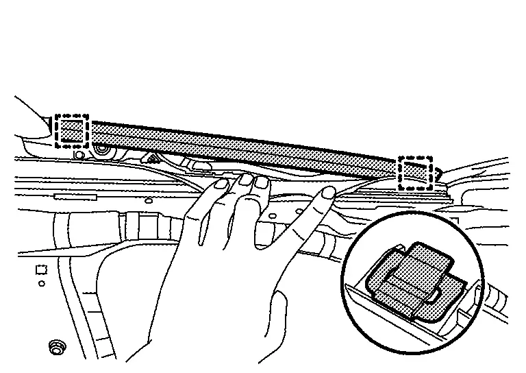
 |
: Metal clip |
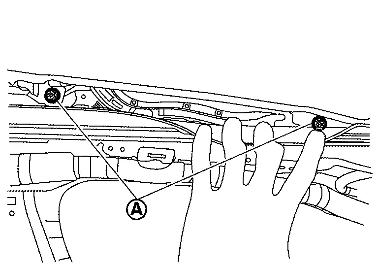
Remove glass lid fixing screws  .
.
Remove glass lid.
INSTALLATION
Note the following items, and then install in the reverse order of removal.
CAUTION:
After installing the glass lid, perform the leak test and check that there is no malfunction.
 NOTE:
NOTE:
-
Before installation, tilt glass lid up so that secure work space.
-
After installation, carry out fitting adjustment. Refer to Adjustment.
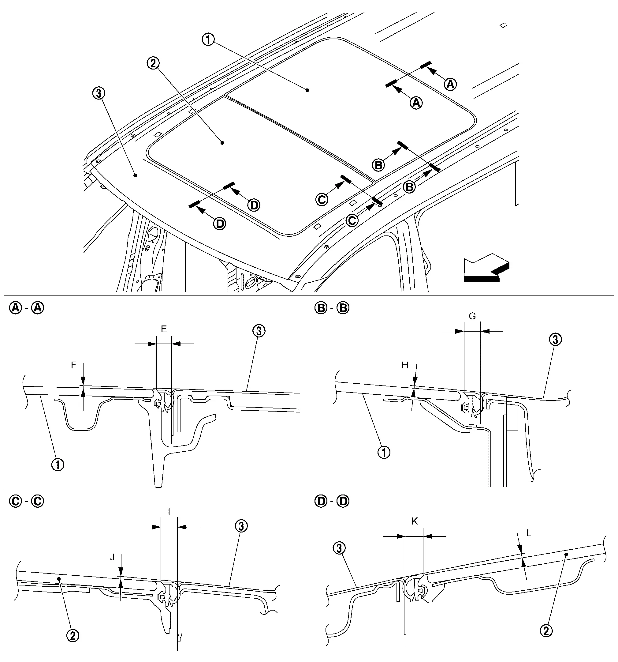
Adjustment
 |
Rear moonroof glass |  |
Glass lid |  |
Roof panel |
| : Nissan Ariya Vehicle front |
If the clearance and the surface height are out of specification, adjust them according to the procedures shown below.
NOTE:
Standard of surface height is given assuming that the glass upper side status is (+), and the glass lower side status is (ŌłÆ) relative to the roof panel.
Unit: mm [in]
| Portion | Standard | |||
|---|---|---|---|---|
| Roof panel ŌĆō Rear moonroof glass | ŌĆō |
E | Clearance |
6.7 ŌĆō 8.3 [0.264 ŌĆō 0.327] |
| F | Surface height |
(ŌłÆ1.0) ŌĆō (+2.4) [(ŌłÆ0.039) ŌĆō (+0.094)] |
||
 ŌĆō ŌĆō |
G | Clearance |
6.6 ŌĆō 8.2 [0.260 ŌĆō 0.323] |
|
| H | Surface height |
(ŌłÆ1.0) ŌĆō (+2.4) [(ŌłÆ0.039) ŌĆō (+0.094)] |
||
| Roof panel ŌĆō Glass lid |  ŌĆō ŌĆō |
I | Clearance |
6.4 ŌĆō 8.0 [0.252 ŌĆō 0.315] |
| J | Surface height |
(ŌłÆ1.0) ŌĆō (+2.4) [(ŌłÆ0.039) ŌĆō (+0.094)] |
||
 ŌĆō ŌĆō |
K | Clearance |
6.4 ŌĆō 8.0 [0.252 ŌĆō 0.315] |
|
| L | Surface height |
(ŌłÆ1.0) ŌĆō (+2.4) [(ŌłÆ0.039) ŌĆō (+0.094)] |
||
Loosen glass lid fixing screws.
Adjust the clearance of glass lid and roof panel according to the fitting standard dimension.
To prevent glass lid from moving after adjustment, first tighten the fixing screw of front left, and then tighten the screw of rear right.
Tighten remaining fixing screws, being careful to prevent glass lid from moving.
Tilt glass lid up and down several times to check that it moves smoothly.
NOTE:
After adjustment the moonroof unit assembly, perform additional service. Refer to Work Procedure.
Other materials:
Automatic Air Conditioning. Removal and Installation
A/c Switch Assembly
Exploded View
A/C switch assembly
Center ventilator finisher
: Pawl
: Nissan Ariya Vehicle front
Removal and Installation
REMOVALRemove center ventilator finisher. Refer to Removal and Installation.
Remove A/C switch assembly fixi ...
Ambient Sensor Signal Circuit
Diagnosis Procedure
CHECK AMBIENT SENSOR POWER SUPPLY
Ignition switch OFF.
Disconnect ambient sensor harness connector.
Ignition switch ON.
Check voltage between ambient sensor harness connector and ground.
(+) (ŌĆō)
Voltage
(Approx.)
Ambient sensor
Connector Termin ...
Dtc/circuit Diagnosis. U3d00-06 Cell Voltage Circuit
DTC Description
DTC DETECTION LOGIC DTC No.
CONSULT screen items
(Trouble diagnosis content) DTC Detection Condition
U3D00-06
Cell voltage circuit
(Cell voltage circuit)
Diagnosis condition
Ignition switch is ON.
Signal (terminal)
BCM (CPU).
Threshold
When a CPU fu ...