Nissan Rogue (T33) 2021-Present Service Manual: Removal and Installation :: Front Suspension Member
Exploded View
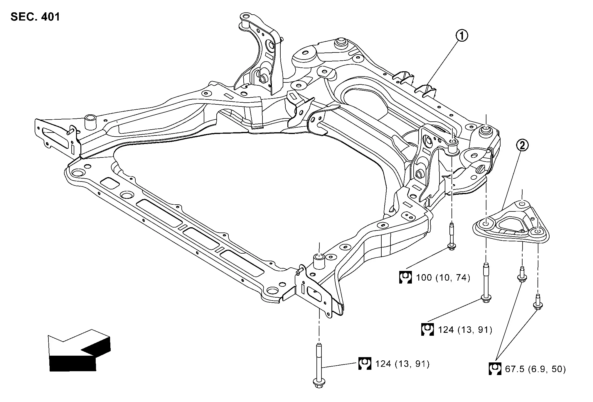
| 1. | Front suspension member | 2. | Member stay | — | — |
| : Nissan Ariya Vehicle front | |||||
 |
: N·m (kg-m, ft-lb) | ||||
Removal and Installation
REMOVAL
Remove tires. Refer to Removal & Installation.
Remove engine under cover. Refer toRemoval and Installation.
-
Remove front bumper fascia. Refer to Removal and Installation.
-
Remove front bumper reinforcement. Refer to Removal and Installation.
-
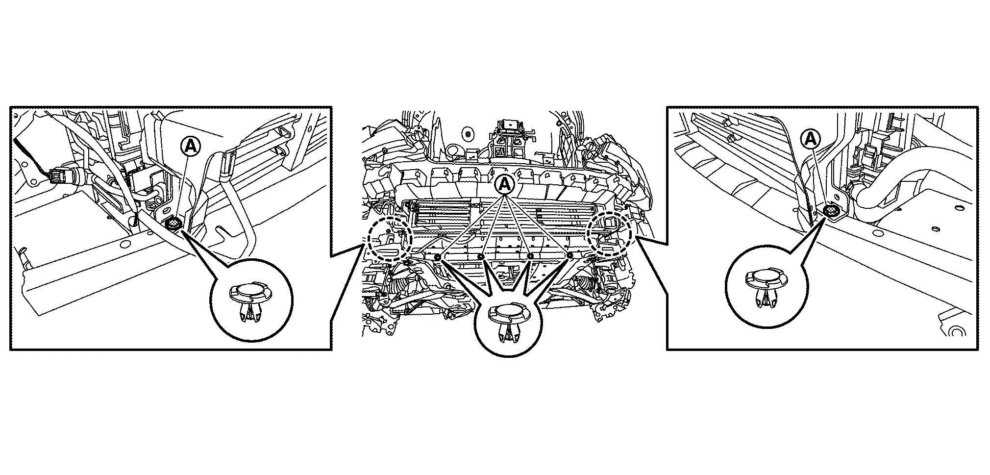
Remove clips (A).
Remove electric water pump mounting bolts, and then secure the electrical water pump to the Nissan Ariya vehicle .
Separate stabilizer connecting rod (strut side) from strut. Refer to Exploded View.
Remove steering outer socket from steering knuckle. Refer to Exploded View.
Separate transverse link from steering knuckle. Refer to Removal and Installation.
Disconnect steering gear and linkage harness connectors.
Remove rear torque rod. Refer to Exploded View.
Remove front exhaust tube mounting bush. Refer to Exploded View.
Secure the radiator and condenser to the Nissan Ariya vehicle.
Set suitable jack under front suspension member.
CAUTION:
-
At this step, the jack must be set only for supporting the removal procedure. For details on jacking up the Nissan Ariya vehicle, refer to Garage Jack and Safety Stand and 2-Pole Lift.
-
Never damage the front suspension member with a jack.
-
Check the stable condition when using a jack.
Remove member stay.
Remove front suspension member mounting bolts.
Gradually lower the jack to remove front suspension member from Nissan Ariya vehicle body.
CAUTION:
Operate while checking that jack supporting status is stable.
 NOTE:
NOTE:
Remove suspension member with stabilizer bar and transverse link.
Remove the following parts.
-
Stabilizer bar: Refer to Removal and Installation.
-
Transverse link: Refer to Removal and Installation.
-
Steering linkage. Refer to Disassembly and Assembly.
Perform inspection after removal. Refer to Inspection.
INSTALLATION
Note the following, and install in the reverse order of removal.
-
To install member stay and mounting bolts of front suspension member, temporarily tighten the bolts before tightening to the specified torque, referring to the tightening method and the numerical order shown below:
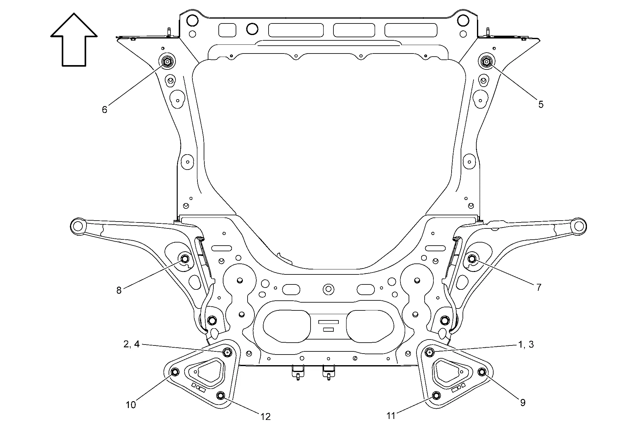
Temporary tightening : 1 → 2 Final tightening (Specified torque) : 3 → 4 → 5 → 6 → 7 → 8 → 9 → 10 → 11 → 12 
: Nissan Ariya Vehicle front -
Perform final tightening of bolts and nuts at the vehicle installation position (rubber bushing), under unladen conditions with tires on level ground.
-
Perform inspection after installation. Refer to Inspection.
Inspection
INSPECTION AFTER REMOVAL
Check front suspension member for cracks, wear or damage. Replace it if necessary.
INSPECTION AFTER INSTALLATION
Check wheel sensor harness for proper connector. Refer to Exploded View.
Check wheel alignment. Refer to Inspection.
Adjust neutral position of steering angle sensor. Refer to Description.
Other materials:
System Description. System (back Door Opener System)
System Description
SYSTEM DIAGRAM Component Function
Back door opener switch
Refer to Back Door Opener Switch.
Back door opener actuator
Refer to Back Door Lock Assembly.
ABS actuator and electric unit (control unit)
Transmit Nissan Ariya vehicle speed signal to BCM via CAN c ...
Mirrors
Inside mirror
Basic information
Adjust the angle of the inside mirror to
the desired position for a clear rearward view in your Nissan Rogue.
Manual anti-glare type (if so
equipped)
The night position 1 will reduce glare
from the headlights of vehicles behind
you at night.
Use the day positio ...
P0719 Brake Pedal Switch B
DTC Description
DTC DETECTION LOGIC DTC
CONSULT screen terms
(Trouble diagnosis content)
DTC detection condition
P0719
Brake pedal switch B
(Brake Switch "B" Circuit Low)
Diagnosis condition
When a deceleration G of -0.13 G or more occurs after the Nissan Ariya vehicle ...