
Nissan Rogue (T33) 2021-Present Service Manual: Removal and Installation :: Front Stabilizer
Exploded View
JAPAN PRODUCTION MODELS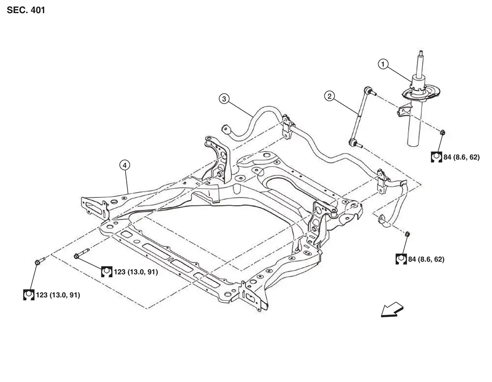
| 1. | Strut | 2. | Stabilizer connecting rod | 3. | Stabilizer bar |
| 4. | Front suspension member | — | — | — | — |
 |
: Nissan Ariya Vehicle front | ||||
 |
: N·m (kg-m, ft-lb) | ||||
NORTH AMERICA PRODUCTION MODELS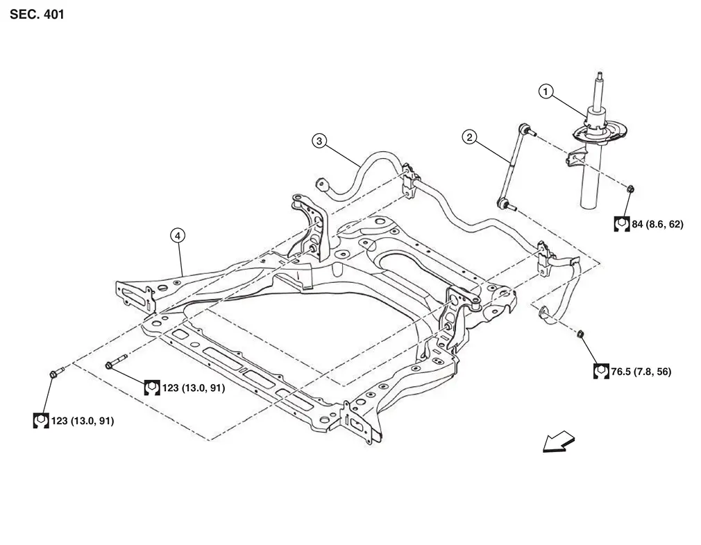
| 1. | Strut | 2. | Stabilizer connecting rod | 3. | Stabilizer bar |
| 4. | Front suspension member | — | — | — | — |
|
: Nissan Ariya Vehicle front | ||||
|
: N·m (kg-m, ft-lb) | ||||
Removal and Installation
REMOVAL
Remove front suspension member. Refer to Removal and Installation.
Remove mounting bolts (A) of stabilizer clamp, and then remove stabilizer clamp and stabilizer bushing from front suspension member.
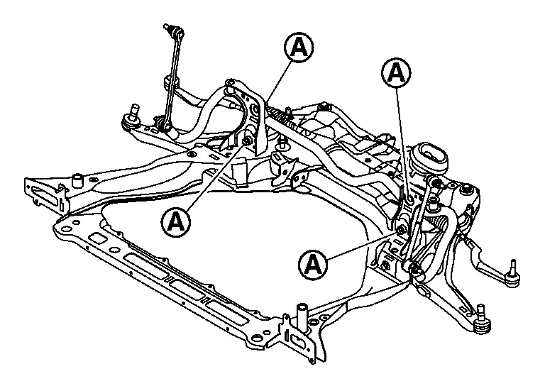
Remove stabilizer bar.
Perform inspection after removal. Refer to Inspection.
INSTALLATION
Note the following, and install in the reverse order of removal.
-
Install stabilizer bar as shown in the figure.
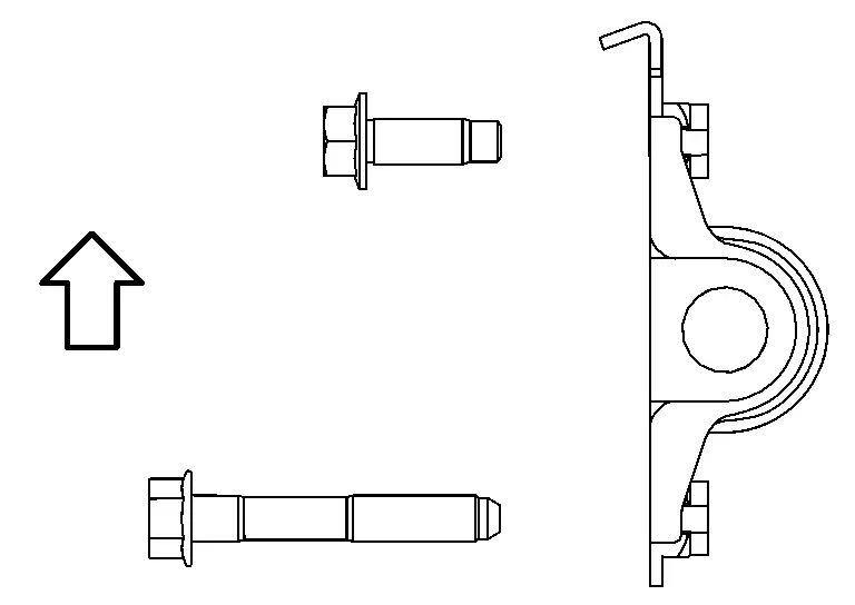
: Upper side -
When installing the stabilizer clamp mounting bolts, tighten in numerical order.
Temporary tightening
(by hand): 1 – 2 Temporary tightening
(by tool): 3→6 Final tightening
(Specified torque): 7→10 : Nissan Ariya Vehicle front 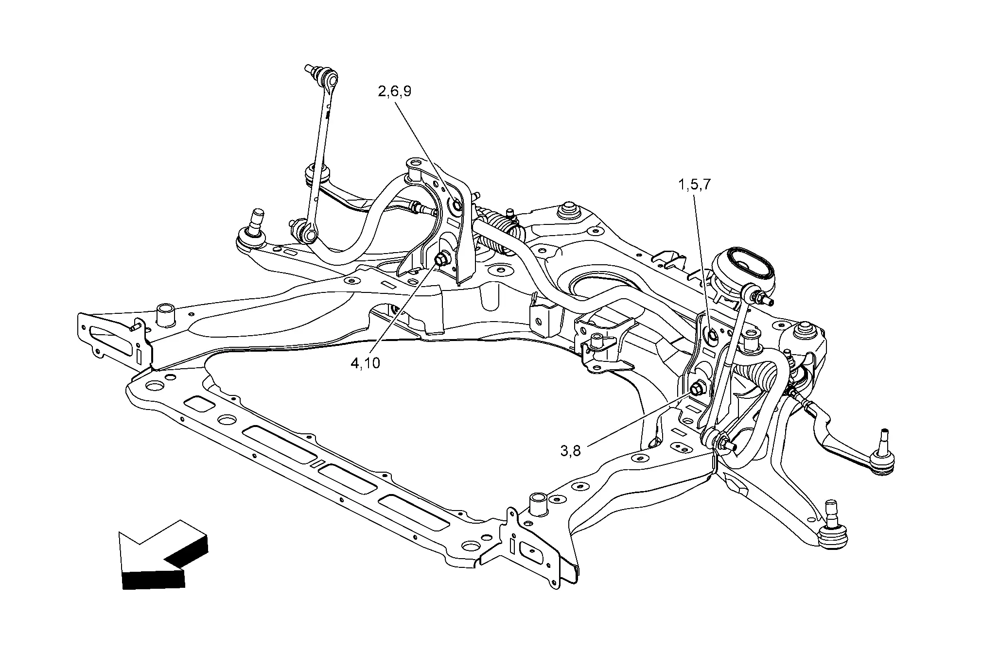
Temporary tightening
(by hand): 1 – 2 Temporary tightening
(by tool): 3→6 Final tightening
(Specified torque): 7→10 : Nissan Ariya Vehicle front -
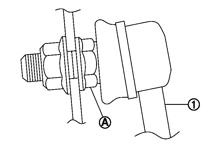
To install stabilizer connecting rod (1), tighten the mounting nut with the hexagonal part (A) on the stabilizer connecting rod side fixed.
-
Perform final tightening of bolts and nuts at the Nissan Ariya vehicle installation position (rubber bushing), under unladen conditions with tires on level ground.
-
Perform inspection after installation. Refer to Inspection.
Inspection
INSPECTION AFTER REMOVAL
Check stabilizer bar, stabilizer connecting rod, stabilizer bushing and stabilizer clamp for deformation, cracks or damage. Replace it if necessary.
INSPECTION AFTER INSTALLATION
Check wheel alignment. Refer to Inspection.
Adjust neutral position of steering angle sensor. Refer to Description.
Other materials:
U214f-57 Mac Comm Error (bcm)
Without Propilot Assist 2.1
DTC Description
DTC DETECTION LOGIC DTC
CONSULT screen terms
(Trouble diagnosis content) DTC detection condition
U214F
57
CAN comm err (BCM)
[Controller area network communication error (Body control module)]
Diagnosis condition
—
Signal (t ...
U2148 Can Comm Circuit
DTC Description
DTC DETECTION LOGIC DTC
CONSULT screen terms
(Trouble diagnosis content)
DTC detection condition
U2148
83
CAN comm err (brake control unit)
[CAN comm err (brake control unit)]
Diagnosis condition
Ignition switch ON
Signal (terminal)
CAN communicati ...
Activation/désactivation du système de freinage d'urgence automatique avec
détection des piétons
Témoin d'avertissement de désactivation du système (tableau de bord)
Écran d'informations du véhicule
Commandes au volant (côté gauche)
Pour activer ou désactiver le système de freinage d'urgence automatique avec détection des piétons du Nissan Rogue, procédez comme suit ...