Nissan Rogue (T33) 2021-Present Service Manual: Removal and Installation :: Transverse Link
Exploded View
JAPAN PRODUCTION MODELS
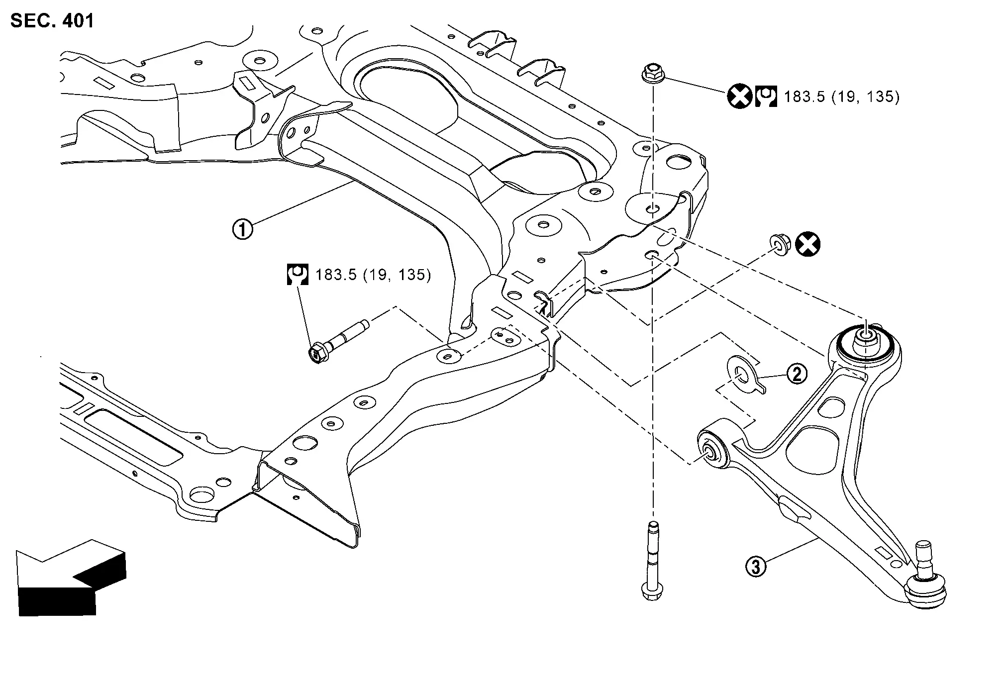
| 1. | Front suspension member | 2. | Bush | 3. | Transverse link |
| : Nissan Ariya Vehicle front | |||||
 |
: N·m (kg-m, ft-lb) | ||||
 |
: Always replace after every disassembly. | ||||
NORTH AMERICA PRODUCTION MODELS
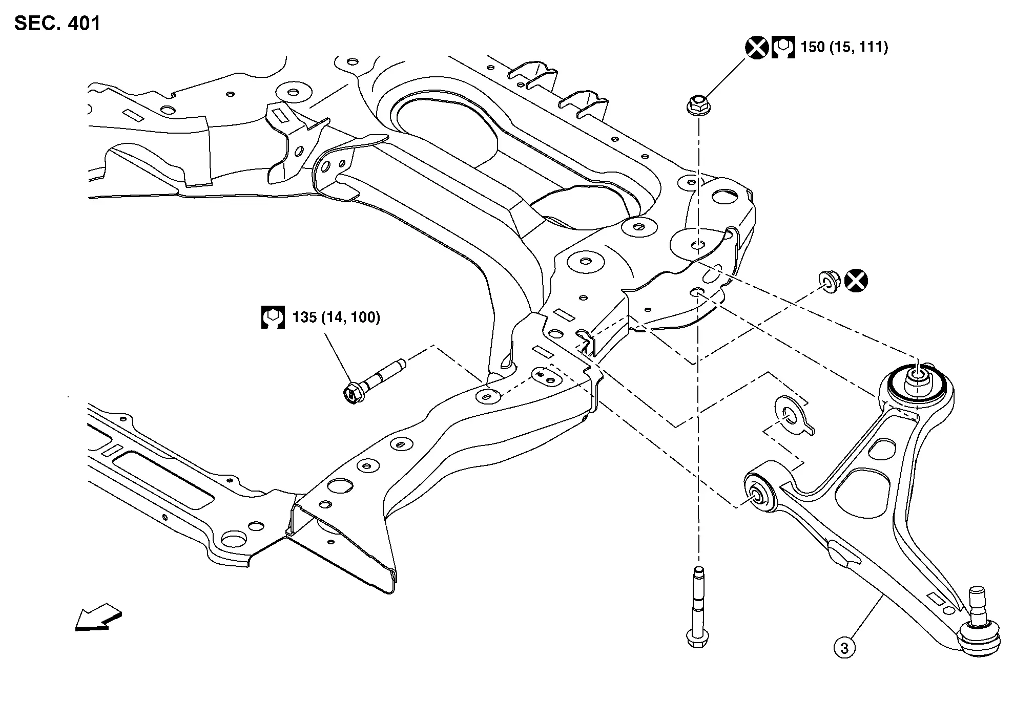
| 1. | Front suspension member | 2. | Bush | 3. | Transverse link |
| : Nissan Ariya Vehicle front | |||||
|
: N·m (kg-m, ft-lb) | ||||
|
: Always replace after every disassembly. | ||||
Removal and Installation
REMOVAL
Remove front suspension member. Refer to Removal and Installation.
Remove transverse link mounting bolts  and nuts
  , and then remove transverse link
  from suspension member.
Perform inspection after removal. Refer to Inspection.
INSTALLATION
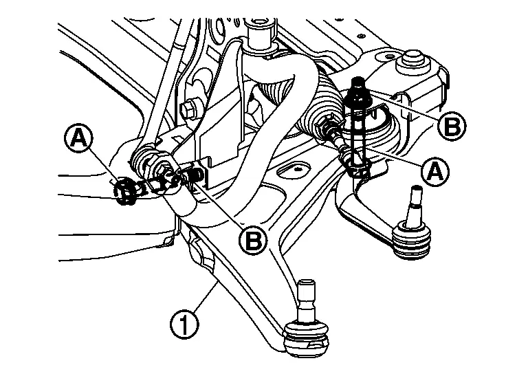
Note the following, and install in the reverse order of removal.
-
Never reuse transverse link mounting nut.
-
Perform final tightening of bolts and nuts at the Nissan Ariya vehicle installation position (rubber bushing), under unladen conditions with tires on level ground.
-
Perform inspection after installation. Refer to Inspection.
Inspection
INSPECTION AFTER REMOVAL
Check the following items, and replace the parts if necessary.
Transverse Link
-
Transverse link for deformation, cracks or damage.
-
Check the bushing for complete separation. (If completely separated, inner metal can be pulled out fromtransverse link.)
-
Ball joint boot for cracks or other damage, and also for grease leakage.
Swing Torque
Manually move ball stud to confirm it moves smoothly with no binding.
Move ball stud at least ten times by hand to check for smooth movement.
Hook a spring balance (A) at cutout on ball stud . Confirm spring balance measurement value is within specifications when ball stud begins moving.

| Swing torque | : Refer to Ball Joint. |
| Measurement on spring balance | : Refer to Ball Joint. |
-
If swing torque exceeds standard range, replace transverse link assembly.
Axial End Play
Move ball stud at least ten times by hand to check for smooth movement.
Move tip of ball stud in axial direction to check for looseness.
-
If there is axial end play, replace transverse link assembly.
INSPECTION AFTER INSTALLATION
Check wheel alignment. Refer to Inspection.
Adjust neutral position of steering angle sensor. Refer to Description.
Other materials:
Manual Air Conditioning. Precaution. Precautions
Precautions
Precaution for Supplemental Restraint System (SRS) "AIR BAG" and "SEAT BELT PRE-TENSIONER"
The Supplemental Restraint System such as “AIR BAG” and “SEAT BELT
PRE-TENSIONER”, used along with a front seat belt, helps to reduce the
risk or severity of injury to the driver and ...
Power Supply and Ground Circuit
A/c Amp.
Diagnosis Procedure
CHECK A/C AMP. GROUND CIRCUIT FOR OPEN
Ignition switch OFF.
Disconnect A/C amp. connector.
Check continuity between A/C amp. harness connector and ground.
A/C amp. (—) Continuity
Connector Terminal
M55
58
Ground
Yes
Is t ...
Mirrors
Inside mirror
Basic information
Adjust the angle of the inside mirror to
the desired position for a clear rearward view in your Nissan Rogue.
Manual anti-glare type (if so
equipped)
The night position 1 will reduce glare
from the headlights of vehicles behind
you at night.
Use the day positio ...