Nissan Rogue (T33) 2021-Present Service Manual: Removal and Installation :: Front Coil Spring and Strut
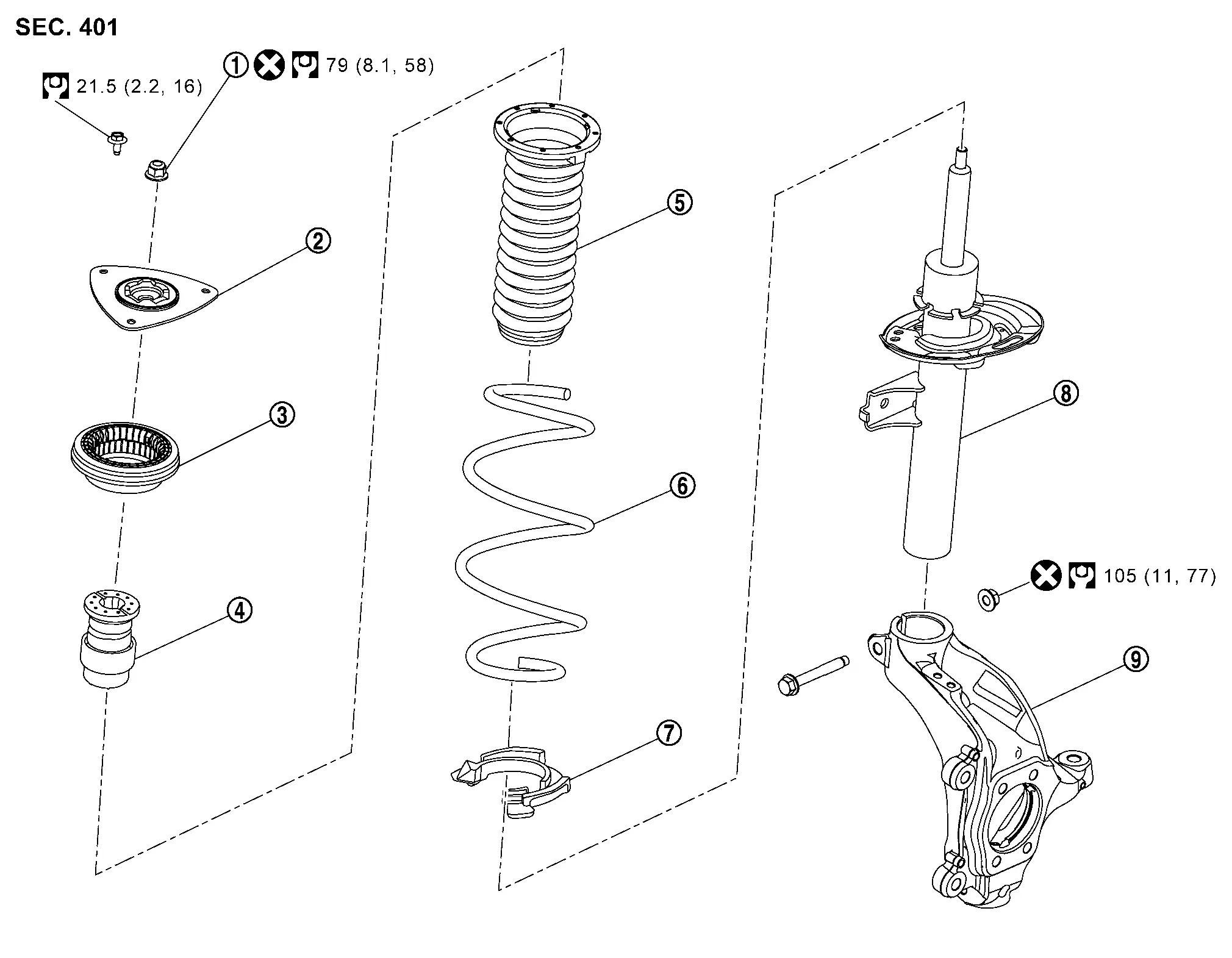
Exploded View
 |
Piston rod lock nut |  |
Mounting insulator |  |
Mounting bearing |
 |
Bound bumper |  |
Upper rubber seat |  |
Coil spring |
 |
Lower rubber seat |  |
Strut |  |
Steering knuckle |
 |
: N·m (kg-m, ft-lb) | ||||
 |
: Always replace after every disassembly. | ||||
Removal and Installation
REMOVAL
Remove cowl top cover. Refer to Removal and Installation.
Remove tires. Refer to Removal & Installation.
Remove wheel hub lock nut.
-
For 2WD: Refer to Removal and Installation.
-
For AWD: Refer to Removal and Installation.
Remove brake hose lock prate. Refer to Removal and Installation.
Remove front wheel sensor. Refer to Removal and Installation.
Remove brake hose bracket. Refer to Removal and Installation.
Remove brake caliper assembly. Hang brake caliper assembly in a place where it will not interfere with work. Refer to Removal and Installation
CAUTION:
Never depress brake pedal while brake caliper is removed.
Remove disc rotor.
-
For 2WD: Refer to Removal and Installation.
-
For AWD: Refer to Removal and Installation.
Remove steering outer socket.
-
For 2WD: Refer to Removal and Installation.
-
For AWD: Refer to Removal and Installation.
Remove trans verse link mounting bolt and nut. Refer to Removal and Installation.
Separate stabilizer connecting rod from strut assembly. Refer to Removal and Installation.
Remove the steering knuckle and strut assembly.
Separate the connection of strut assembly and steering knuckle as follows.
CAUTION:
Be sure to keep the following procedure because steering knuckle may be damaged when you enlarge the gap of steering knuckle too much.
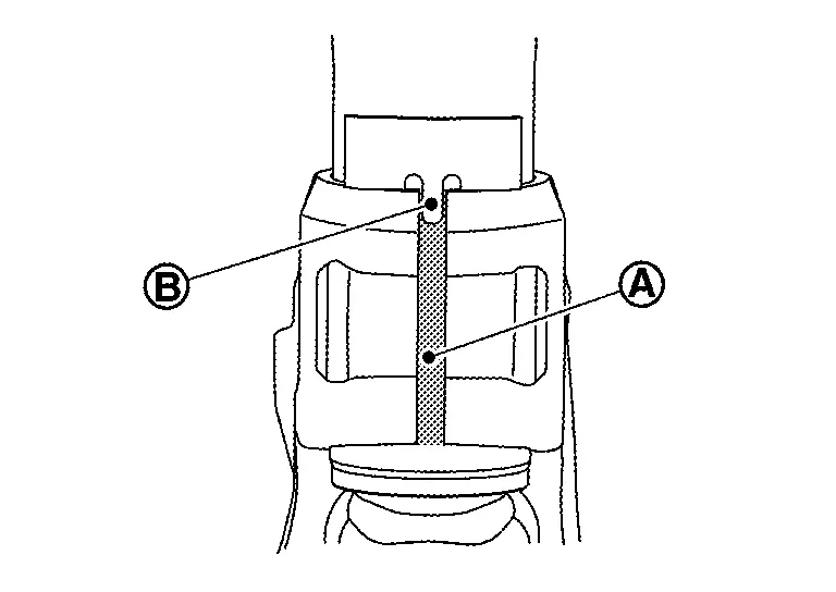
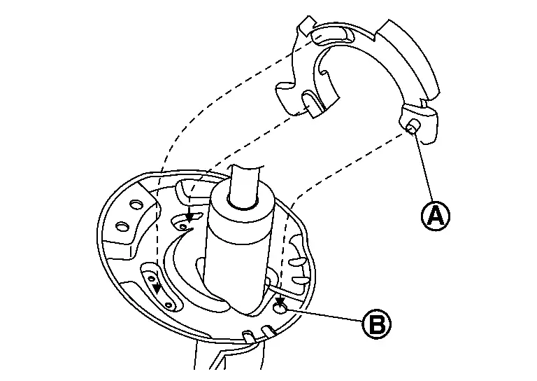
Remove strut mounting bolts from steering knuckle. Measure the gap (A) of the steering knuckle. And then mark the enlarged limit (B) to the chisel.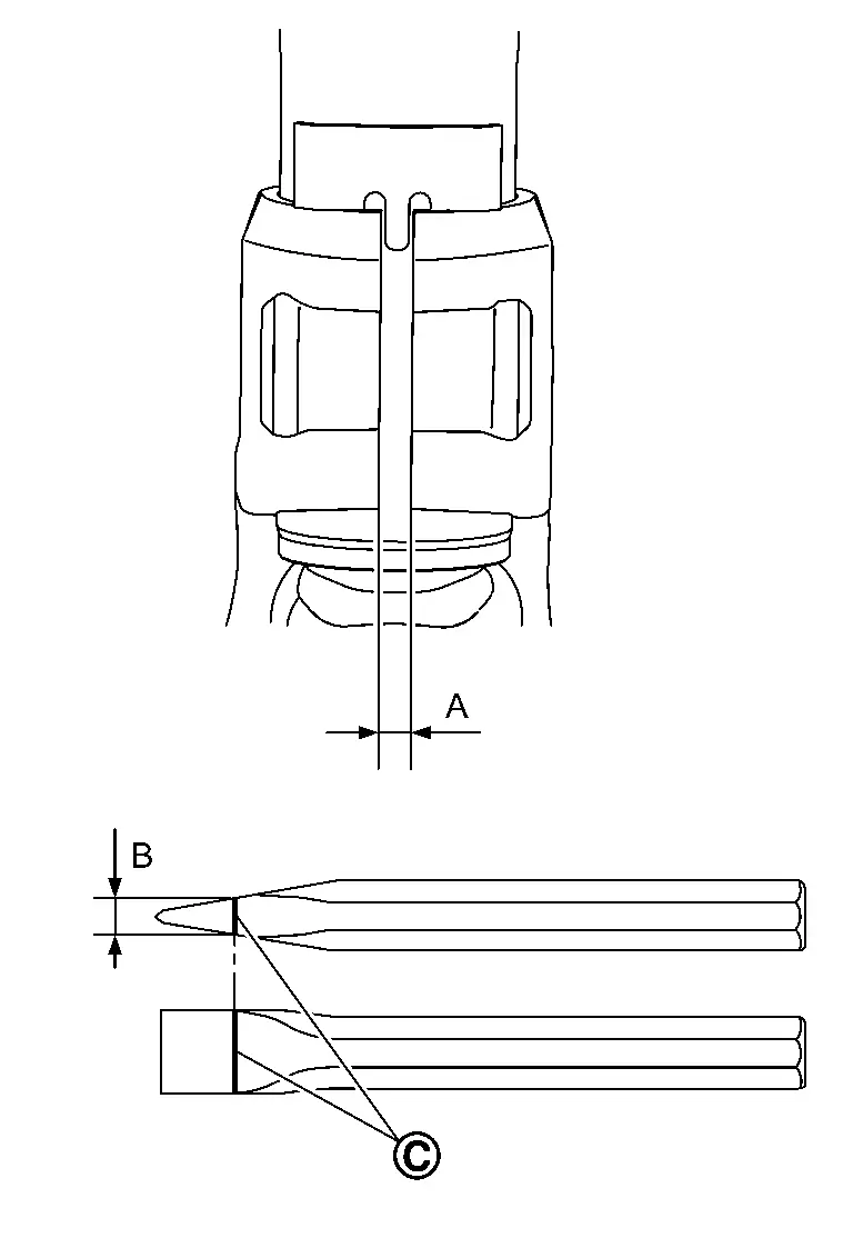
 |
Marking |
| Enlarged limit (B) = gap (A) + 2.5 mm (0.098 in) |
 NOTE:
NOTE:
Standard of gap: 6.9 ± 0.5 mm (2.56 ± 0.02 in)
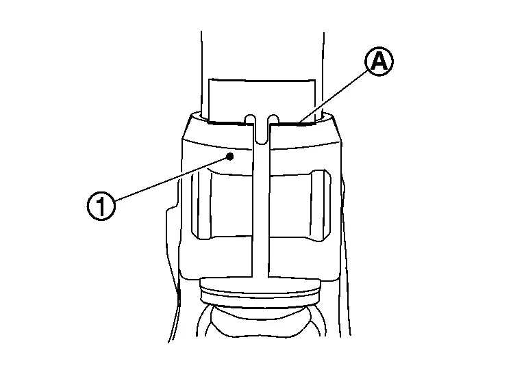
Enlarge the gap of the steering knuckle with the chisel (A) (commercial service tool) not to surpass a limit as shown in the figure.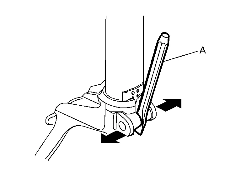
CAUTION:
-
Never enlarge the gap more than 2.5mm (0.098in).
-
Be careful not to damage the projection
 and strut assembly
  with the chisel.
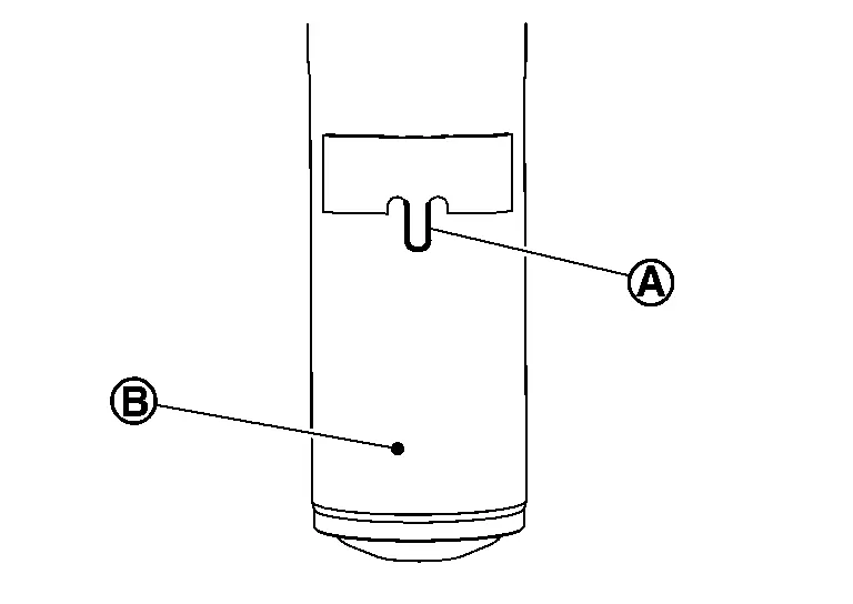
CAUTION:
-
Never place drive shaft joint at an extreme angle.
-
Be careful not to overextend slide joint.
-
Never allow drive shaft to hang down without support for joint sub-assembly, shaft and the other parts.
-
Be sure to remove lubricants if lubricant has been used to separate the connection of strut assembly and steering knuckle.
Remove mounting bolt of mounting insulator, and then remove strut assembly.
INSTALLATION
Note the following, and install in the reverse order of removal.
Strut Assembly
-
When installing strut assembly to the vehicle, set the mounting insulator to the direction shown in the figure.
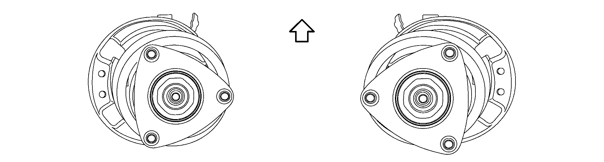

: Nissan Ariya Vehicle front CAUTION:
Never reuse strut mounting nut.
-
Perform final tightening of fixing parts at the Nissan Ariya vehicle installation position (rubber bushing), under unladen conditions with tires on level ground.
-
Perform inspection after installation. Refer to Inspection.
-
After replacing the strut, always follow the disposal procedure to discard the strut. Refer to Disposal.
Strut Assembly and Steering Knuckle Connection
CAUTION:
Be sure to remove lubricants if lubricant has been used to separate the connection of strut assembly and steering knuckle.
Install the steering knuckle to strut assembly as follows.
Set suitable jack under steering knuckle.
Align the gap of steering knuckle to the projection part of strut.
Tighten the mounting bolt with pushing up the steering knuckle until contacts stopper bracket end face, using a suitable jack.
CAUTION:
Check the stable condition when using a jack.
Disassembly and Assembly
DISASSEMBLY
CAUTION:
Never damage strut assembly piston rod when removing components from strut assembly.
Install strut attachment (A) (SST: ST35652000) to strut assembly and secure it in a vise.
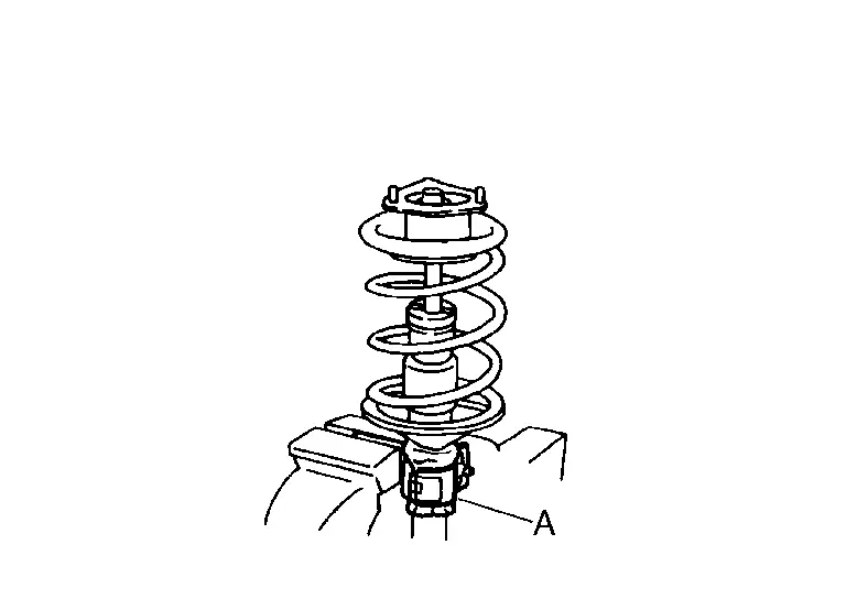
CAUTION:
When installing the strut attachment to strut assembly, wrap a shop cloth around strut to protect from damage.
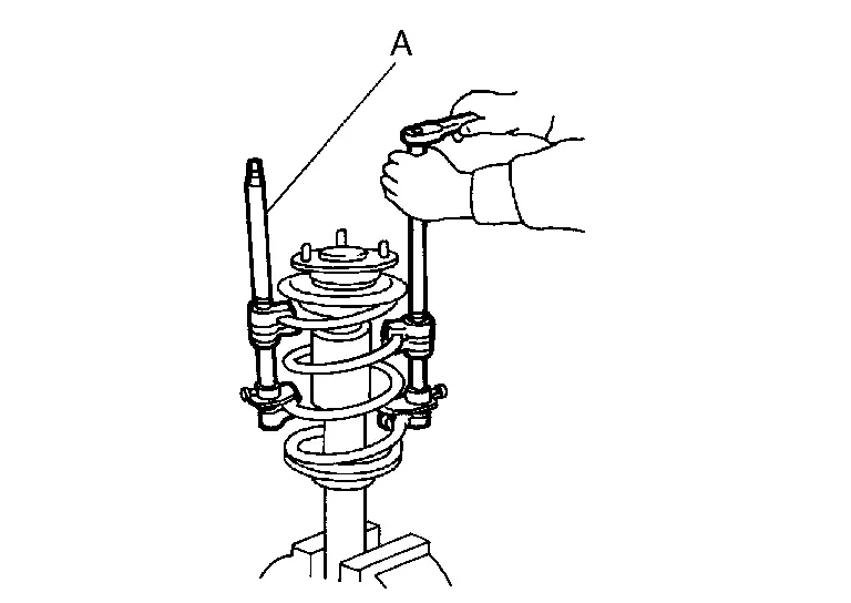
Using a spring compressor (A) (commercial service tool), compress coil spring between spring upper seat and lower seat (strut assembly) until coil spring with a spring compressor is free.
CAUTION:
Be sure a spring compressor is securely attached to coil spring. Compress coil spring.
Check coil spring with a spring compressor between spring upper seat and lower seat (strut assembly) is free. And then remove piston rod lock nut while securing the piston rod tip so that piston rod does not turn.
Remove mounting insulator, mounting bearing, upper rubber seat and bound bumper from strut.
After removing coil spring with a spring compressor (commercial service tool), then gradually release a spring compressor.
CAUTION:
Loosen while making sure coil spring attachment position does not move.
Remove lower rubber seat.
Remove strut attachment (A) (SST: ST35652000) from strut.
Perform inspection after disassembly. Refer to Inspection.
ASSEMBLY
CAUTION:
Never damage strut assembly piston rod when installing components from strut assembly.
Install strut attachment (SST: ST35652000) to strut and secure it in a vise.
CAUTION:
When installing the strut attachment to strut assembly, wrap a shop cloth around strut to protect from damage.
Install lower rubber seat with its protrusion on the lower area aligned with the hole on the strut.
Compress coil spring using a spring compressor (commercial service tool), and install it onto strut assembly.
CAUTION:
-
Be sure a spring compressor is securely attached to coil spring, before compress coil spring.
-
Align the lower end of coil spring
with lower rubber seat as shown in the figure.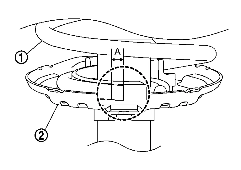
Dimension (A) : 5 mm (0.20 in) or less -
Set coil spring so that its paint marks are aligned with the position from the bottom end of the coil spring as shown in the figure.
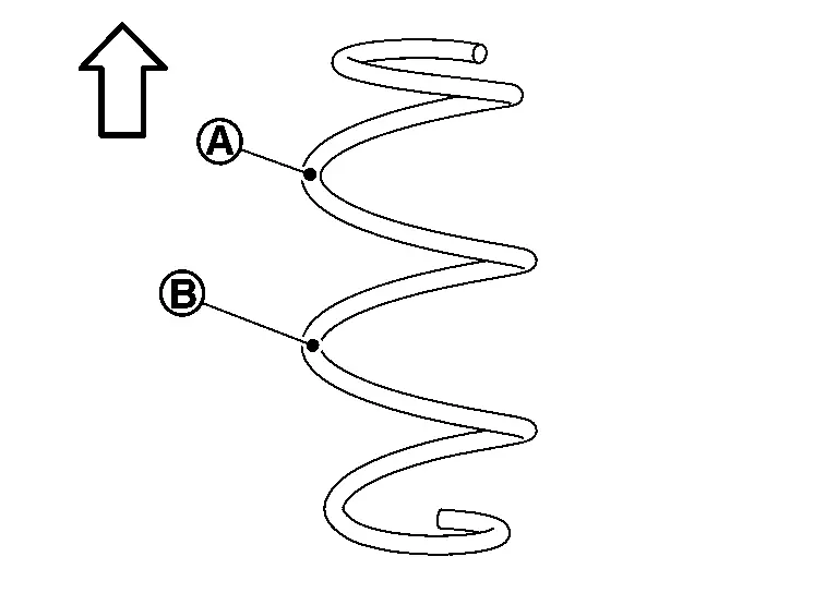
: Upper side Japan production MODELS : 2.5 turns : 1.5 turns North America production MODELS : 2.25 turns : 1.25 turns
Apply soapy water to bound bumper.
CAUTION:
Never use machine oil.
Set bound bumper to piston rod of strut.
Install mounting bearing, mounting insulator and upper rubber seat on to spring.
CAUTION:
Never apply oils, such as grease, when installing the mounting bearing and mounting insulator.
Set the mounting insulator to the direction shown in the figure, and then install the mounting insulator, the upper rubber seat and the mounting bearing to the strut.
| : Nissan Ariya Vehicle front |
CAUTION:
-
Align the upper end of coil spring
with upper rubber seat as shown in the figure.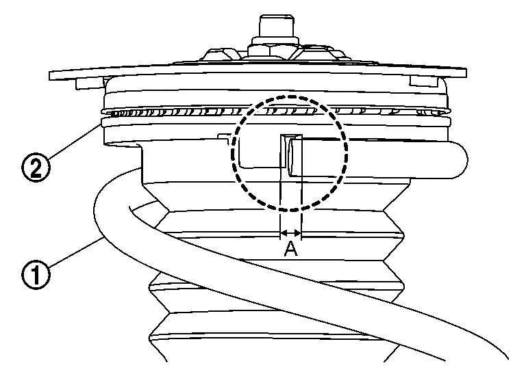
Dimension (A) : 5 mm (0.20 in) or less
Secure piston rod tip so that piston rod does not turn, then tighten piston rod lock nut with specified torque.
CAUTION:
Never reuse piston rod lock nut.
Gradually release a spring compressor (A) (commercial service tool), and remove coil spring.
CAUTION:
Loosen while making sure coil spring attachment position does not move.
Remove the strut attachment (A) (SST: ST35652000) from strut assembly.
Inspection
INSPECTION AFTER DISASSEMBLY
Check the following items, and replace the parts if necessary.
Strut
-
Strut for deformation, cracks or damage
-
Piston rod for damage, uneven wear or distortion
-
Oil leakage
Strut Mounting Insulator and Bound Bumper
Check strut mounting insulator and bound bumper for cracks, wear or damage.
Coil Spring
Check coil spring for cracks, wear or damage.
INSPECTION AFTER INSTALLATION
Check wheel sensor harness for proper connector. Refer to Exploded View.
Check wheel alignment. Refer to Inspection.
Adjust neutral position of steering angle sensor. Refer to Description.
Disposal
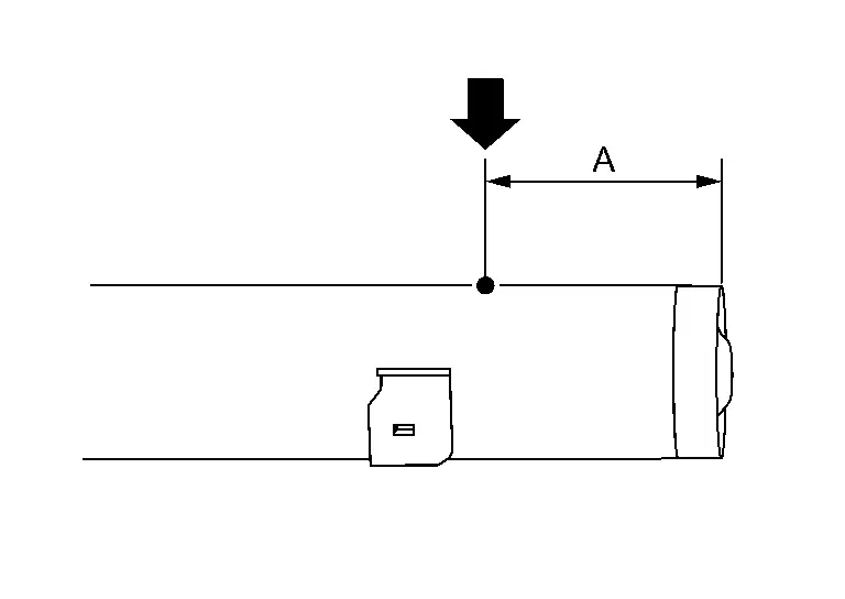
Set strut assembly horizontally to the ground with the piston rod fully extracted.
Drill 2 – 3 mm (0.08 – 0.12 in) hole at the position ( ) from top as shown in the figure to release gas gradually.
CAUTION:
-
Wear eye protection (safety glasses).
-
Wear gloves.
-
Be careful with metal chips or oil blown out by the compressed gas.
NOTE:
-
Drill vertically in this direction show by arrow.
-
Directly to the outer tube avoiding brackets.
-
The gas is clear, colorless, odorless, and harmless.
| A | : 20 – 30 mm (0.79 – 1.18 in) |
Position the drilled hole downward and drain oil by moving the piston rod several times.
CAUTION:
Dispose of drained oil according to the law and local regulations.
Other materials:
Ring Gear Shaft
Kr15ddt
Exploded View
Drive pinion lock nut
Companion flange
Dust shield
Drive pinion oil seal
Pinion bearing assembly
O-ring
Drive pinion adjusting shim
Drive pinion
O-ring
Transfer case oil seal
Dowel pin
Plug
Gasket
T ...
System
System Description
DESCRIPTION
ADAS* control unit 2 controls the following systems, based on CAN communication signal from each control unit.
NOTE:
*: Advanced Driver Assistance Systems
AEB
RAB
ProPILOT Assist 1.1
ProPILOT Assist 2.1
I-FCW
LDW
I-LI
I-B ...
System Description. Component Parts. Door Lock System
Door Lock System
Power Door Lock System
Component Parts Location
No. Component Function
1.
Back door opener switch
Back door opener switch sends signal to BCM to open the back door.
2.
Back door lock assembly
Refer to Back Door Lock Assembly.
3.
Rear door lock ass ...