
Nissan Rogue (T33) 2021-Present Service Manual: Removal and Installation :: Rear Washer Nozzle and Tube
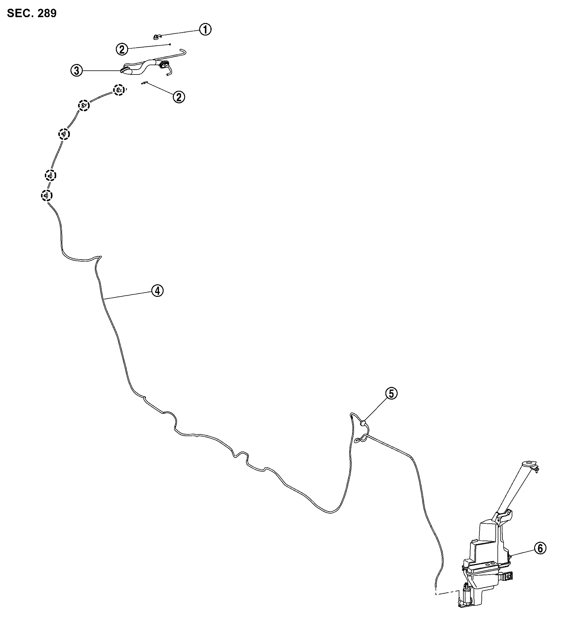
Exploded View
 |
Rear washer nozzle |  |
Joint |  |
Rear washer tube B |
 |
Rear washer tube A |  |
Grommet |  |
Washer tank |
 |
: Clip | ||||
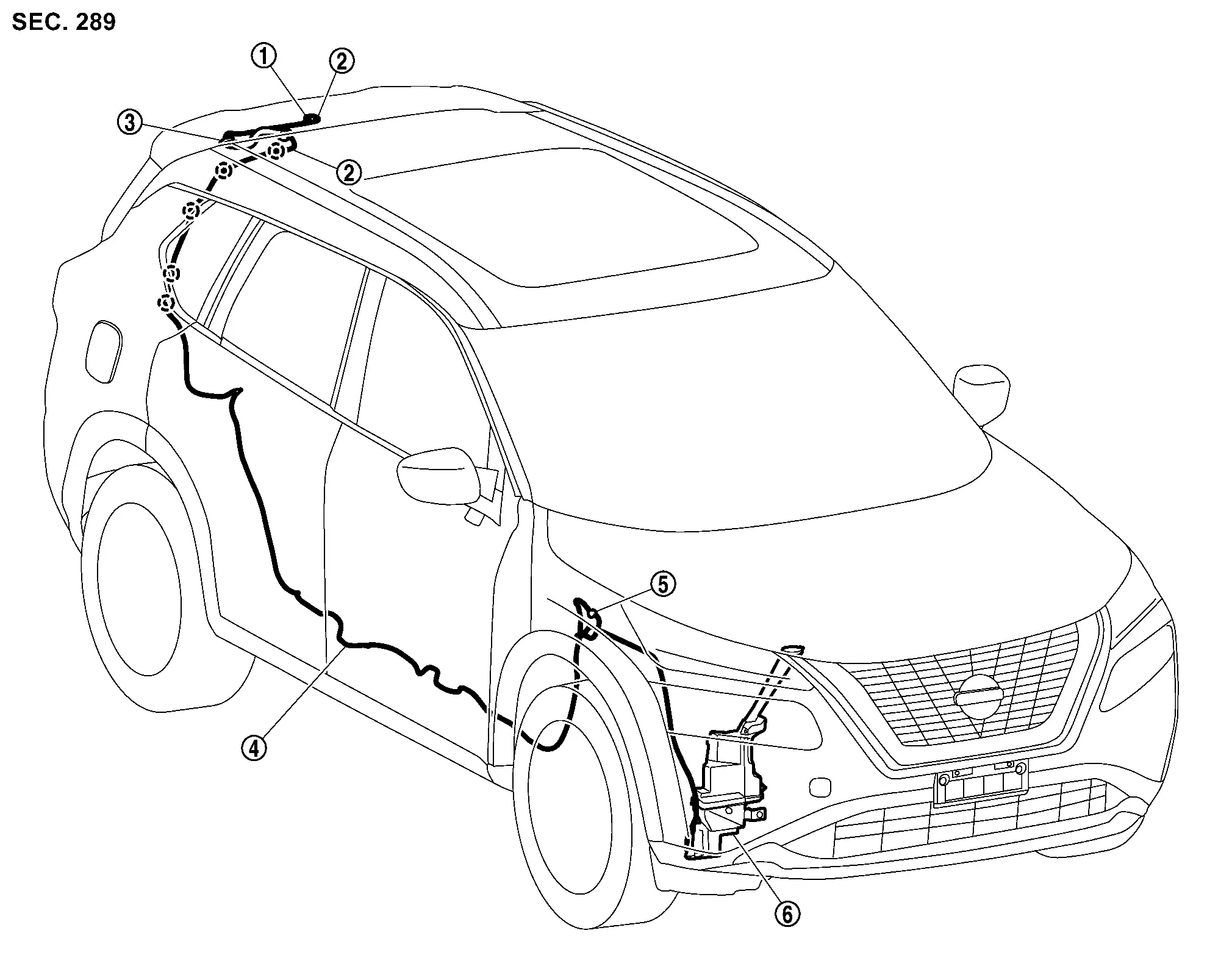
Hydraulic Layout
|
Rear washer nozzle | |
Joint | |
Rear washer tube B |
|
Rear washer tube A | |
Grommet | |
Washer tank |
|
: Clip | ||||
Rear Washer Nozzle
Removal and Installation
REMOVAL
CAUTION:
When washer tube is disconnected/removed, washer fluid may come out so prepare a container to receive the fluid and never allow fluid to be sprinkled.
Remove high-mounted stop lamp. Refer to Removal and Installation.
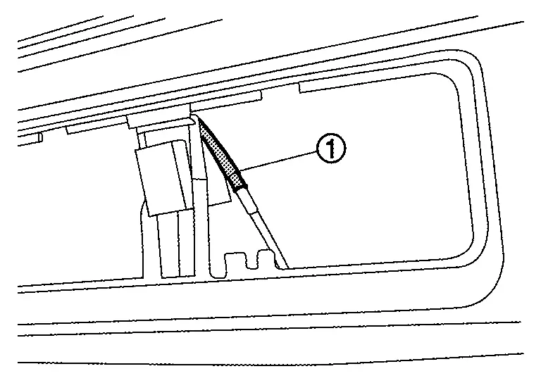
Disconnect rear washer nozzle from joint.
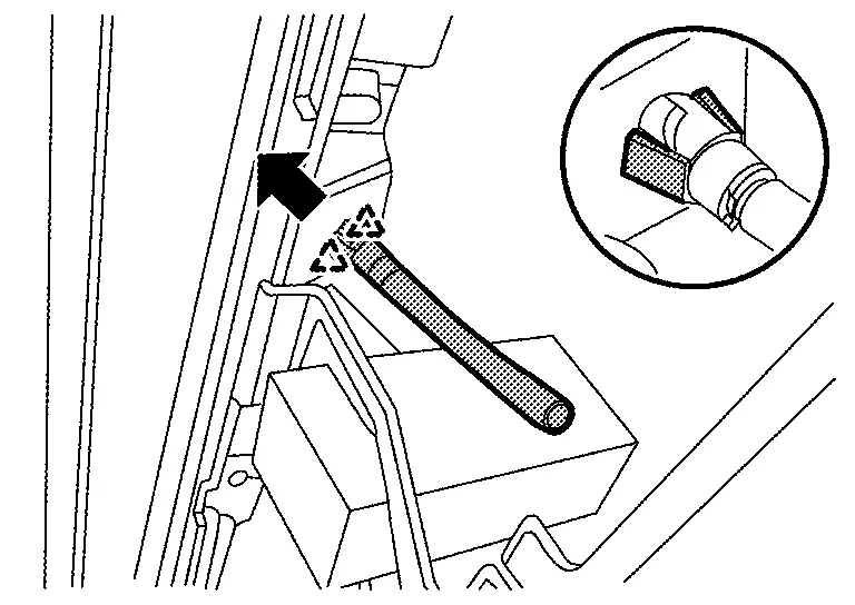
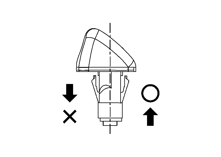
While holding rear washer nozzle fixing pawls, push up in the direction of the arrow in the figure, and then remove rear washer nozzle.
 |
: Pawl |
INSTALLATION
Note the following items, and then install in the reverse order of removal.
CAUTION:
-
Before installation, check rear washer nozzle. Refer to Inspection and Adjustment.
-
After installation, check rear washer nozzle spray position. Refer to Inspection and Adjustment.
Inspection and Adjustment
INSPECTION
Rear Washer Nozzle (Check Valve Function) Inspection
Check that air can pass through by blowing forward direction [toward washer nozzle], and check that air cannot pass through by sucking reverse direction [toward washer tank].
ADJUSTMENT
Rear Washer Nozzle Spray Position Adjustment
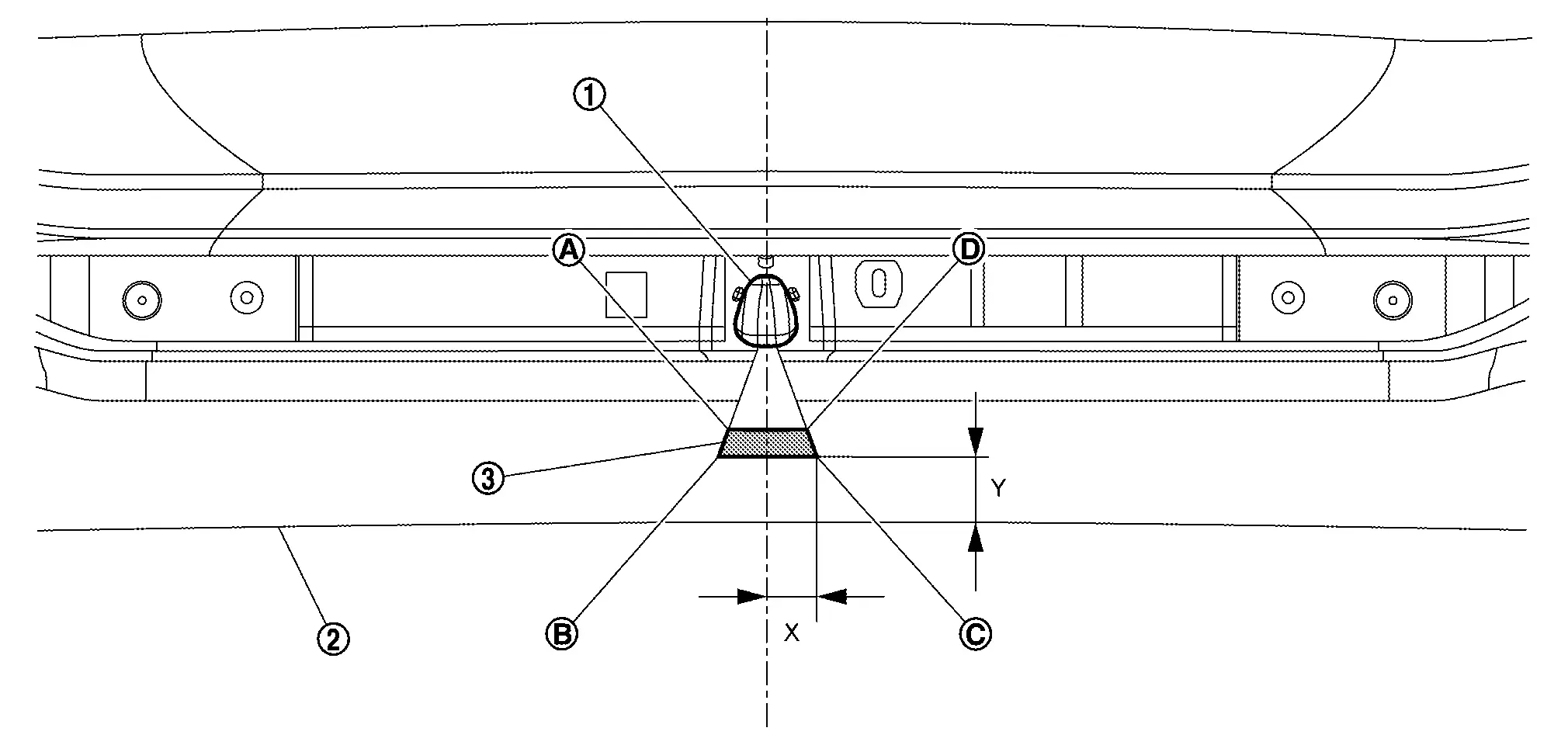
Adjust spray positions to match the positions shown in the figure.
|
Rear washer nozzle | |
Black print line | |
Spray area |
| Spray position | X | Y |
|---|---|---|
 |
11.4 mm (0.449 in) | 26.3 mm (1.035 in) |
 |
12.6 mm (0.496 in) | 18.6 mm (0.732 in) |
 |
12.6 mm (0.496 in) | 26.3 mm (1.035 in) |
 |
11.4 mm (0.449 in) | 18.6 mm (0.732 in) |
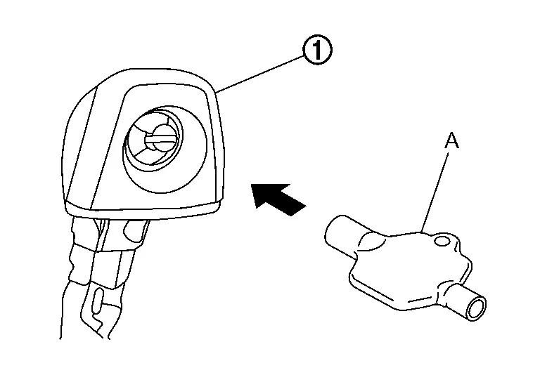
Use washer nozzle adjuster (A) for rear washer nozzle adjustment.
Rear Washer Tube
Removal and Installation
REMOVAL
CAUTION:
-
Replacement of a single part is not possible due to the adoption of rear washer tube B. For replacement, replace back door assembly as a set.
-
When washer tube is disconnected/removed, washer fluid may come out so prepare a container to receive the fluid and never allow fluid to be sprinkled.
Remove fender protector RH. Refer to Removal and Installation.
Disconnect rear washer tube A from front and rear washer pump.
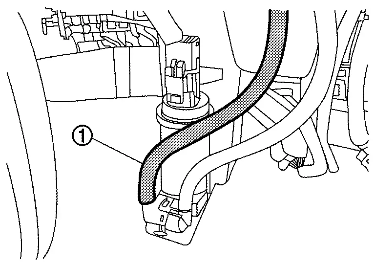
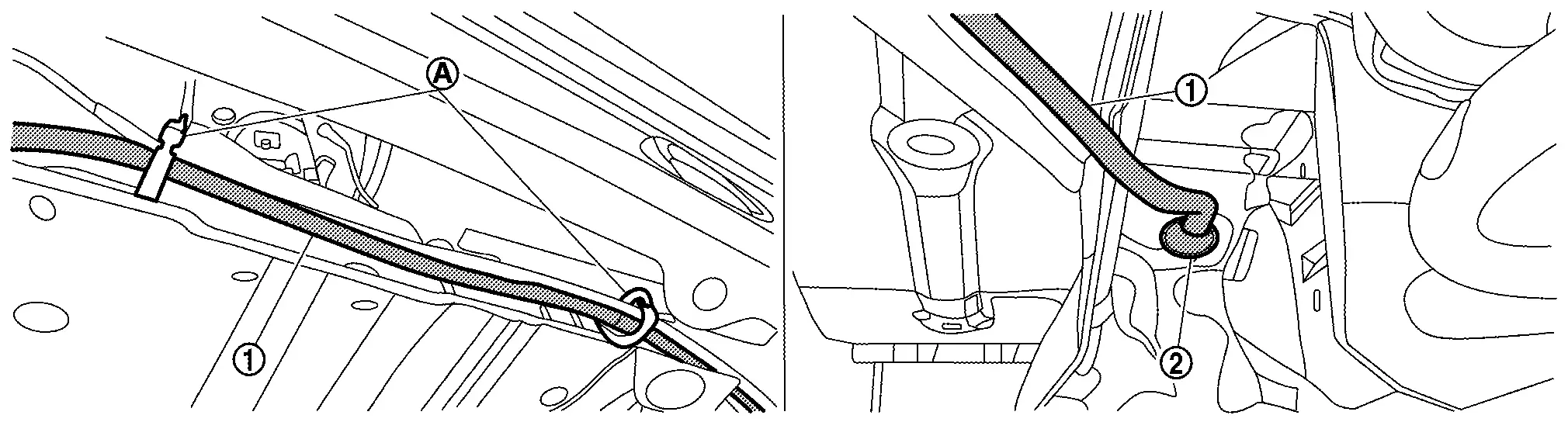
Disconnect rear washer tube A from fixing clips and remove grommet , and then pull in rear washer tube A of inside the Nissan Ariya vehicle.
Remove steering member. Refer toRemoval and Installation.
Remove center pillar lower garnish RH. Refer to Removal and Installation.
Remove luggage side upper finisher RH. Refer to Removal and Installation.
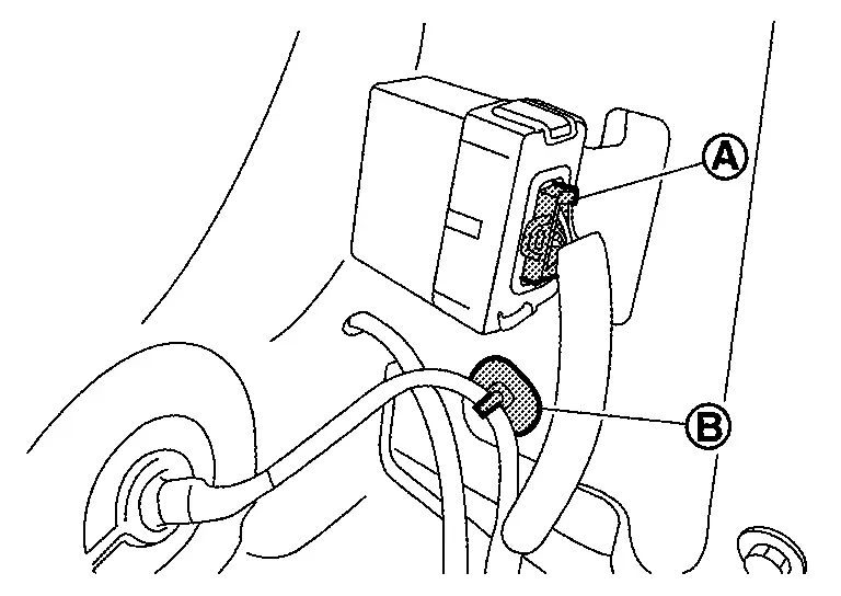
Disconnect harness connector (A) and remove harness clip (B).
Remove insulator.
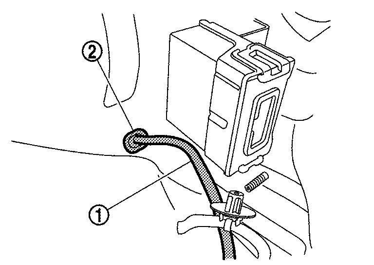
Remove grommet (2), and then rear washer tube A (1).
Remove rear washer tube A from harness protector.
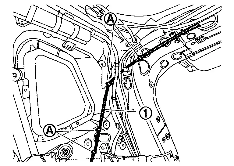
Remove rear washer tube A (1) fixing clips (A).
Remove rear end of headlining to make work space. Refer to Removal and Installation.
Disconnect rear washer tube A (1) from joint, and then remove rear washer tube A.
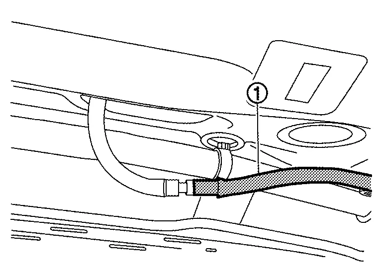
Remove rear washer nozzle. Refer to Removal and Installation.
Remove grommet, and then remove rear washer tube B.
INSTALLATION
Note the following items, and then install in the reverse order of removal.
CAUTION:
-
Align washer tube marking to the vehicle installation position.
-
Install grommet in the installation hole surely.
Other materials:
Removal and Installation. Vacuum Lines
Exploded View
Brake booster
Clamp
Vacuum hose 1
Vacuum pump
Vacuum hose 2
Clip
Intake manifold
Check valve
Paint mark (White)
Paint mark (Pink)
Paint mark (Yellow)
Stamp indicating the direction of engine (Yellow)
& ...
System maintenance
To ensure proper operation of the driver monitoring system on the Nissan Rogue, keep the camera and surrounding area clean. Use a soft, damp cloth—such as one designed for lens cleaning—wrung out thoroughly, and gently wipe the surface to remove dust or dirt.
License information (ProPILOT Ass ...
P14a7 Charge Air Cooler Cooling Electric Water Pump
DTC Description
DTC DETECTION LOGIC DTC
CONSULT screen terms
(Trouble diagnosis content)
DTC detection condition
P14A7
Charge air cooler cooling electric W/P
(Charge air cooler cooling electric water pump)
Diagnosis condition
Engine running at idle
Warm-up conditio ...