Nissan Rogue (T33) 2021-Present Service Manual: System Description :: System
System Description (Heated Steering Wheel)
SYSTEM DIAGRAM
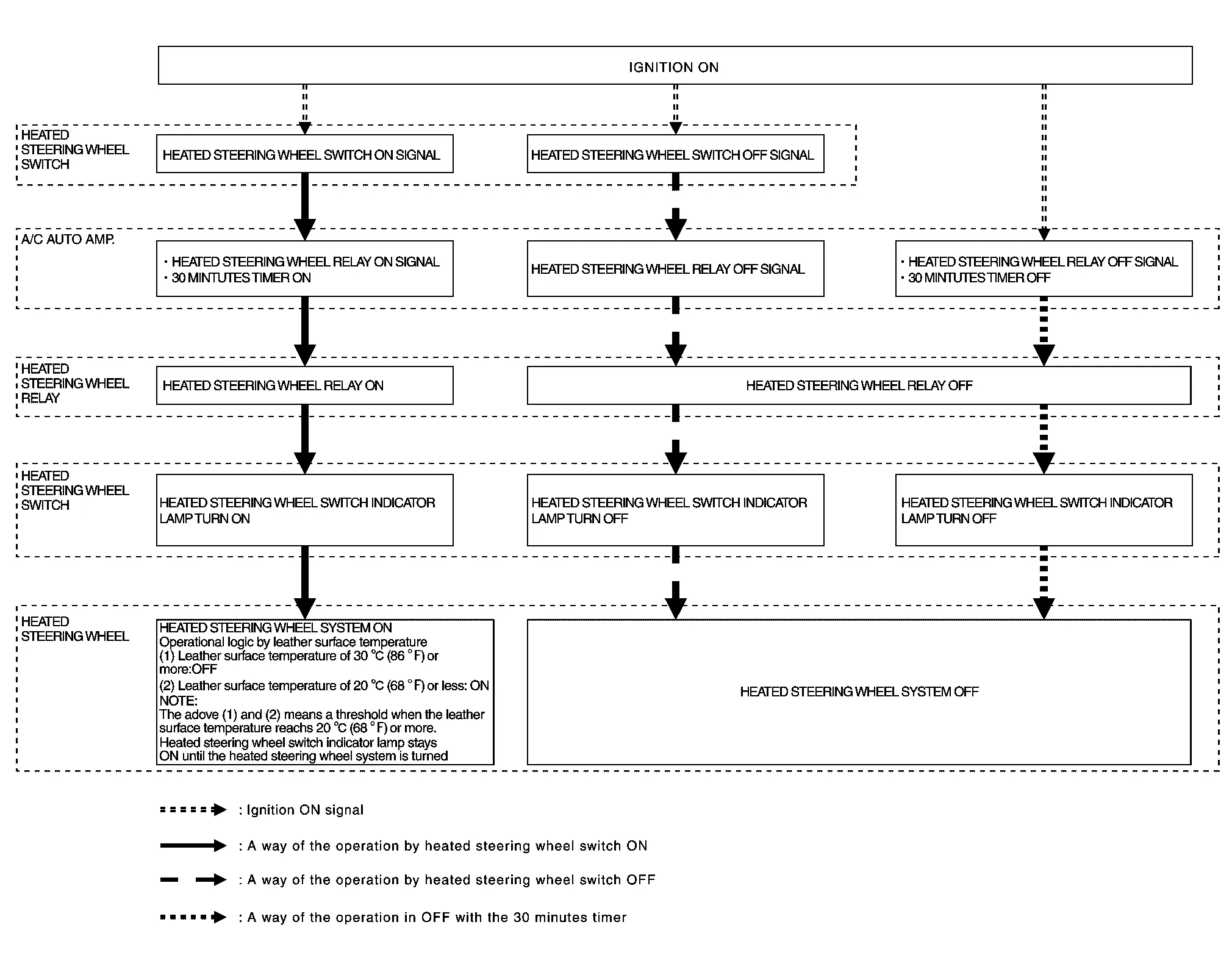
The heated steering wheel switch controls the heated steering wheel relay. When the heated steering wheel switch is turned on, the heated steering wheel relay is energized and the heated steering wheel system will operate. The heated steering wheel system will turn off when the heated steering wheel temperature reaches approximately 86┬░F (30┬░C). Heated steering wheel system operation can also be canceled by pressing the heated steering wheel switch again. The A/C amp. Incorporates a timer and turns OFF the heated steering wheel relay when operating time reaches a certain time.
 NOTE:
NOTE:
If the surface temperature of the steering wheel is below 68┬░F (20┬░C), the system will heat the steering wheel and cycle off and on to maintain a temperature above 68┬░F (20┬░C). The indicator light will remain on as long as the system is on. Push the switch again to turn the heated steering wheel system off manually. The indicator light will go off.
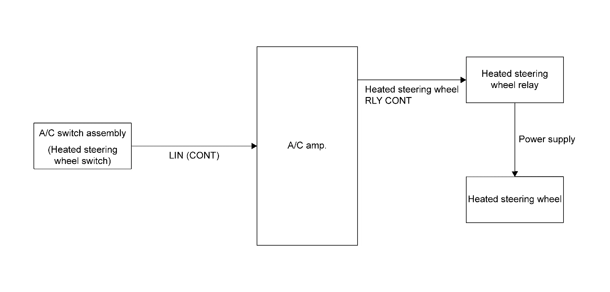
CIRCUIT DIAGRAM
Other materials:
Dtc/circuit Diagnosis. Power Supply and Ground Circuit
Power Window Main Switch
Diagnosis Procedure
CHECK FUSE
Ignition switch OFF, and then wait for 3 minutes with driver door open.
NOTE:
Even after ignition switch is OFF, power is supplied to accessories for a certain amount of timer by the AUTO ACC function.
When Nissan Ariya vehicl ...
C1f05-54 Front Camera Unit
DTC Description
DTC DETECTION LOGIC DTC
CONSULT screen terms
(Trouble diagnosis content) DTC detection condition
C1F05
54
Front camera unit
(Front camera unit)
Diagnosis condition
When AEB system is ON
When driving the Nissan Ariya vehicle
Signal (te ...
Diagnosis System (bcm)
Common Item
CONSULT Function (BCM - COMMON ITEM)
BCM
Refer to CONSULT Function (BCM - COMMON ITEM).
Flasher
CONSULT Function (BCM - FLASHER)
BCM
Refer to CONSULT Function (BCM - FLASHER).
...