Nissan Rogue (T33) 2021-Present Service Manual: Ring Gear Shaft
Kr15ddt
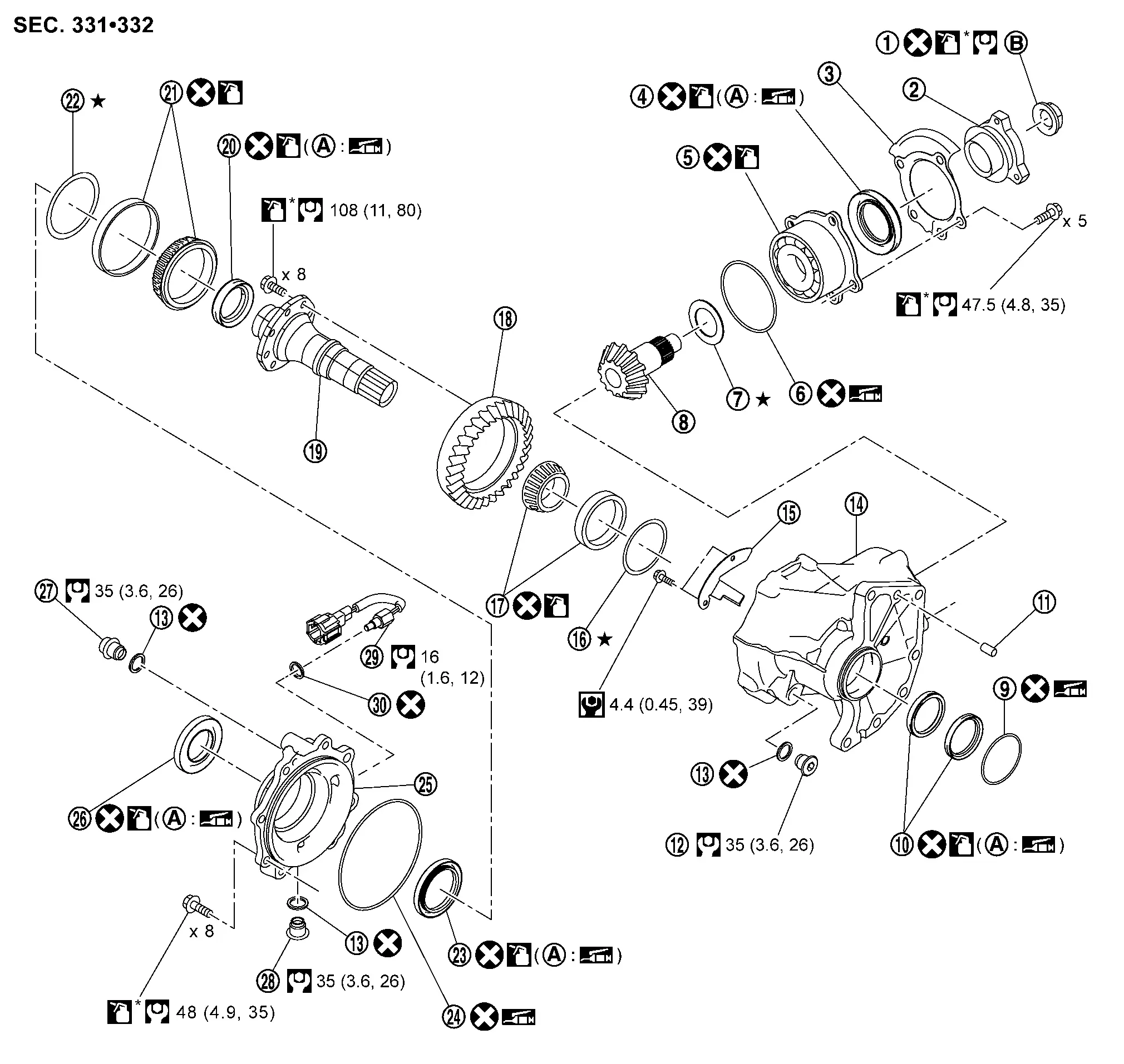
Exploded View
 |
Drive pinion lock nut |  |
Companion flange |  |
Dust shield |
 |
Drive pinion oil seal |  |
Pinion bearing assembly |  |
O-ring |
 |
Drive pinion adjusting shim |  |
Drive pinion |  |
O-ring |
 |
Transfer case oil seal |  |
Dowel pin |  |
Plug |
 |
Gasket |  |
Transfer case |  |
Baffle plate |
 |
Ring gear bearing adjusting shim (transfer case side) |  |
Ring gear bearing (transfer case side) |  |
Ring gear |
 |
Ring gear shaft |  |
Drive shaft oil seal |  |
Ring gear bearing (transfer cover side) |
 |
Ring gear bearing adjusting shim (transfer cover side) |  |
Transfer cover oil seal |  |
O-ring |
 |
Transfer cover |  |
Transfer cover dust seal |  |
Filler plug |
 |
Drain plug |  |
Transfer oil temperature sensor |  |
Gasket |
 |
Oil seal lip |  |
Comply with the assembly procedure when tightening. Refer to Disassembly and Assembly. | ||
 : N┬Ęm (kg-m, in-lb) : N┬Ęm (kg-m, in-lb) |
|||||
 : N┬Ęm (kg-m, ft-lb) : N┬Ęm (kg-m, ft-lb) |
|||||
 : Always replace after every disassembly. : Always replace after every disassembly. |
|||||
 : Select with proper thickness. : Select with proper thickness. |
|||||
 : Apply transfer oil. : Apply transfer oil. |
|||||
| *: Apply anti-corrosive oil. |
|||||
 : Apply multi-purpose grease. : Apply multi-purpose grease. |
|||||
Disassembly and Assembly
DISASSEMBLY
Remove transfer cover assembly. Refer to Disassembly and Assembly.
Remove ring gear bearing outer race (transfer cover side) and ring gear bearing adjusting shim (transfer cover side) from the transfer cover. Refer to Disassembly and Assembly.
Remove ring gear shaft assembly from the transfer case.
Remove ring gear bearing outer race (transfer case side) and ring gear bearing adjusting shim (transfer case side) from the transfer case. Refer to Disassembly and Assembly.
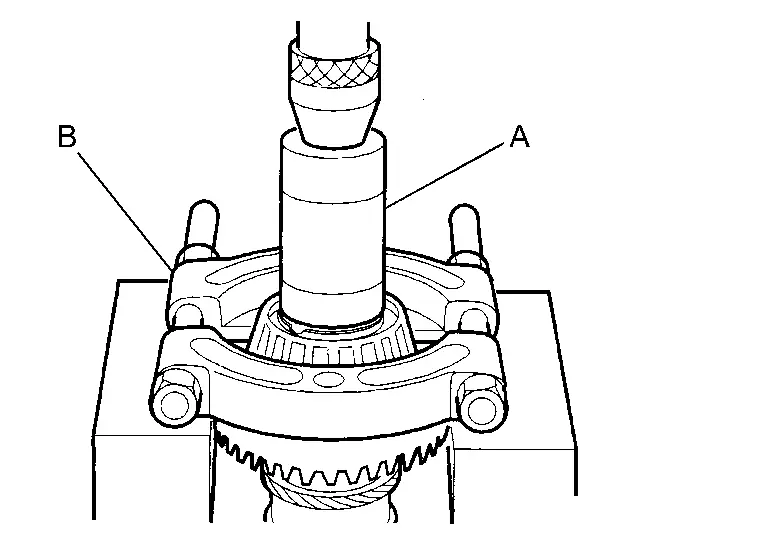
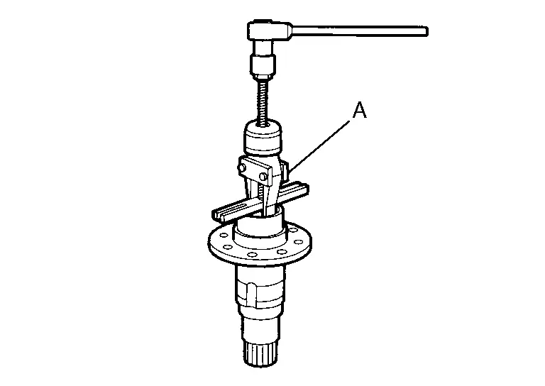
Remove ring gear bearing inner race (transfer cover side) from ring gear shaft using drift (A) (commercial service tool) and separator (B) (commercial service tool).
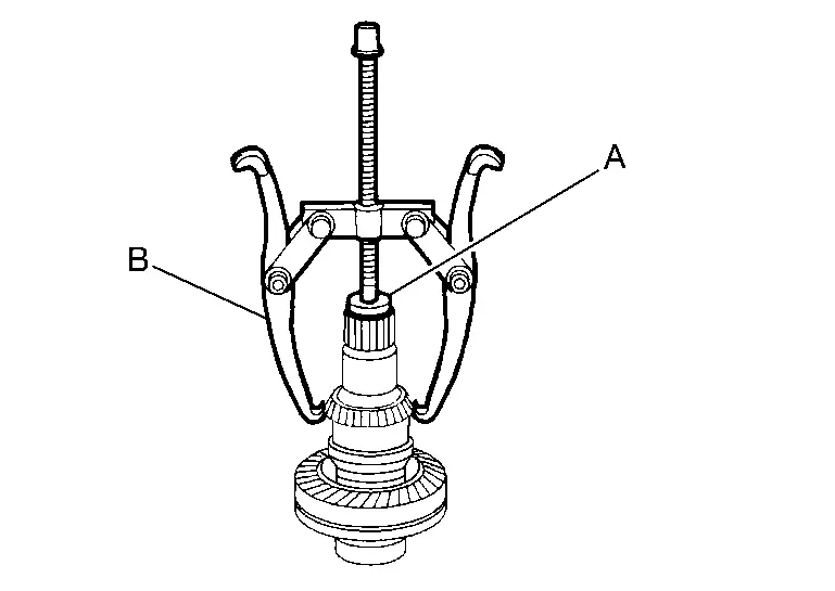
Remove ring gear bearing inner race (transfer case side) from ring gear shaft with drift (A) [SST: ST33061000 (NI-8107-2)] and puller (B) (commercial service tool).
Remove the ring gear mounting bolts.
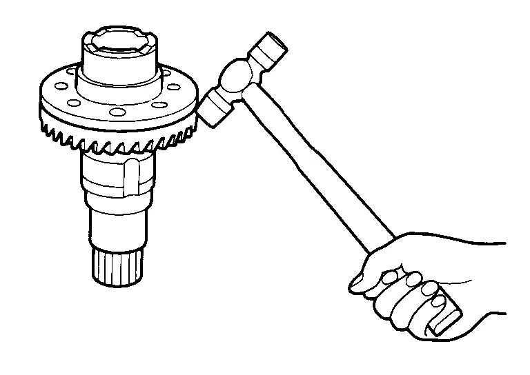
Lightly tap ring gear with a plastic hammer to remove ring gear from the ring gear shaft.
Remove drive shaft oil seal from the ring gear shaft with the puller (A) [SST: KV381054S0 (NI-34286)].
Perform inspection after disassembly. Refer to Inspection.
ASSEMBLY
Using drift (A) (commercial service tool), install drive shaft oil seal within the dimension (L) shown as follows.
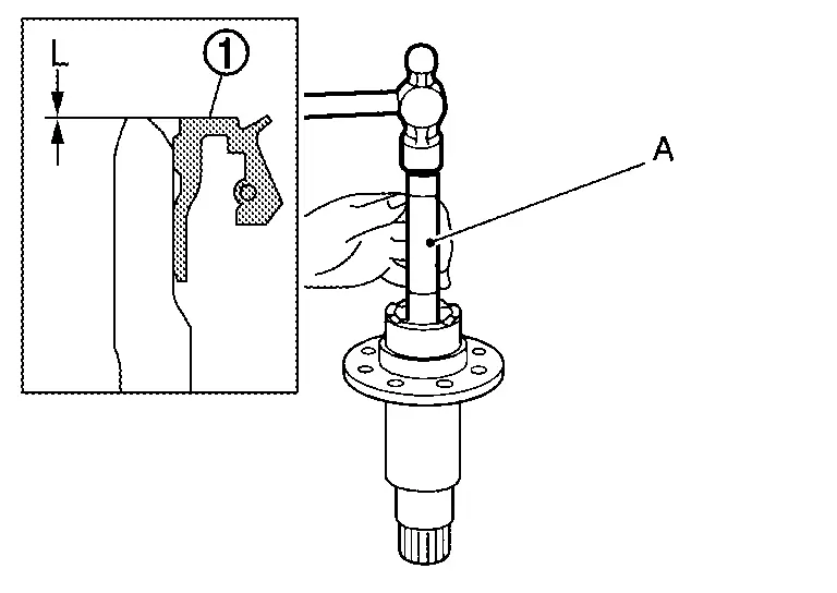
| L | : 2.0 +0.6/ŌłÆ0 mm (0.079 +0.024/ŌłÆ0 in) |
 NOTE:
NOTE:
The positive value is deeper than the ring gear shaft end face.
CAUTION:
-
Never reuse the oil seal.
-
When installing, never incline oil seal.
-
Apply multi-purpose grease onto oil seal lips, and transfer oil onto the circumference of the oil seal.
Select ring gear bearing adjusting shim (transfer case side) and ring gear bearing adjusting shim (transfer cover side). Refer to Adjustment.
Assemble the selected ring gear bearing adjusting shim (transfer case side) and ring gear bearing outer race (transfer case side) to transfer case. Refer to Disassembly and Assembly.
CAUTION:
-
Never reuse ring gear bearing (transfer case side).
-
Apply transfer oil to the ring gear bearing (transfer case side).
Assemble the selected ring gear bearing adjusting shim (transfer cover side) and ring gear bearing outer race (transfer cover side) to transfer cover. Refer to Disassembly and Assembly.
CAUTION:
-
Never reuse ring gear bearing (transfer cover side).
-
Apply transfer oil to the ring gear bearing (transfer cover side).
Install the ring gear to ring gear shaft, and apply anti-corrosive oil onto thread and seats on the mounting bolts. Then tighten mounting bolts to the specified torque.
-
For tightening torque, refer to Exploded View.
Install ring gear bearing inner race (transfer cover side) with drift (A) (commercial service tool).
CAUTION:
-
Never reuse ring gear bearing (transfer cover side).
-
Apply transfer oil to the ring gear bearing (transfer cover side).
Install the ring gear bearing inner race (transfer case side) to ring gear shaft with drift (A) (commercial service tool).
CAUTION:
-
Never reuse ring gear bearing (transfer case side).
-
Apply transfer oil to the ring gear bearing (transfer case side).
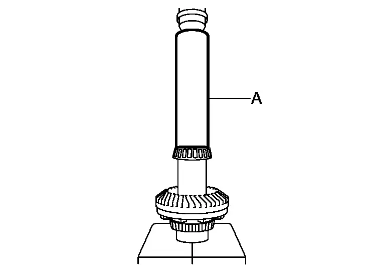
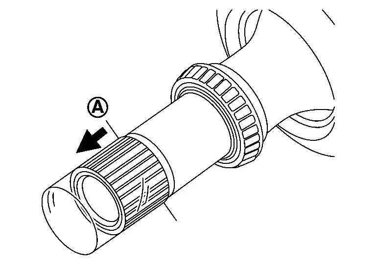
Install the ring gear shaft assembly to the transfer case.
CAUTION:
Protect transfer case oil seals beforehand from being damaged by the spline of ring gear shaft below method following.
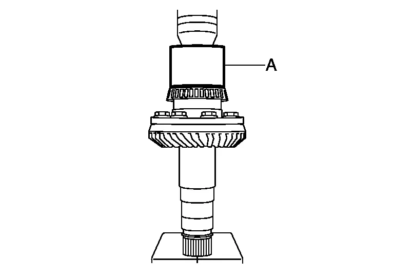
Apply multi-purpose grease to spline part indicated in the figure.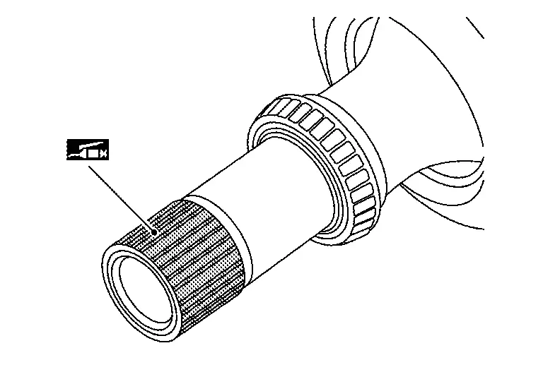
|
: Limit line of wrapping |
CAUTION:
Never wrap sliding surfaces on oil seal.
NOTE:
A plastic bag can be used by cutting it to fit.
Install transfer cover to check and adjust each part. Refer to Disassembly and Assembly.
NOTE:
At this timing, O-ring installing to transfer cover is not necessary. Install O-ring after backlash and tooth contact are checked.
Check backlash, tooth contact, total preload and companion flange runout. Refer to Adjustment.
CAUTION:
Measure the total preload without oil seals of transfer cover and transfer case.
Reinstall transfer cover to install O-ring. Refer to Disassembly and Assembly.
After installing transfer case oil seals, remove wrapped vinyl from the spline of ring gear shaft.
Inspection
INSPECTION AFTER DISASSEMBLY
Check items below. If necessary, replace them with new ones.
Gear and Shaft
Check gear face and shaft for wear, cracks, damage, and seizure.
CAUTION:
If malfunction is detected on the ring gear or drive pinion, replace the ring gear and drive pinion as a set.
Bearing
Check for seizure, peeling, wear, corrosion, sticking, unusual noise, roughness in hand turning, and other damage.
CAUTION:
When replacing the bearing, always replace the inner race and outer race as a pair.
Shim
Check for seizure, damage, and unusual wear.
Other materials:
B2e32-11 Av Control Unit
DTC Description
DTC DETECTION LOGIC DTC No.
CONSULT screen terms
(Trouble diagnosis content) DTC detection condition
B2E32-11
Audio unit
(Audio unit)
Diagnosis condition
When ignition switch is ON
Signal (terminal)
Sound signal
Threshold
0.5 V or less
Diagnosi ...
Installing top tether strap
WARNING
Child restraint anchorages are designed only for correctly installed restraints. Never attach adult seat belts or other equipment to these pointsŌĆödoing so may damage the anchors and compromise safety.
Avoid hooking the tether strap on the seatback carpet. Always use the designated ...
Symptom Diagnosis. Noise, Vibration and Harshness (nvh) Troubleshooting
NVH Troubleshooting Chart
Use chart below to find the cause of the symptom. If necessary, repair or replace these parts. Possible cause and SUSPECTED PARTS Symptom Reference
FRONT SUSPENSION
Noise Shake Vibration Shimmy Judder Poor quality ride or
Improper installation, looseness
...