Nissan Rogue (T33) 2021-Present Service Manual: Transfer Cover
Kr15ddt
Exploded View
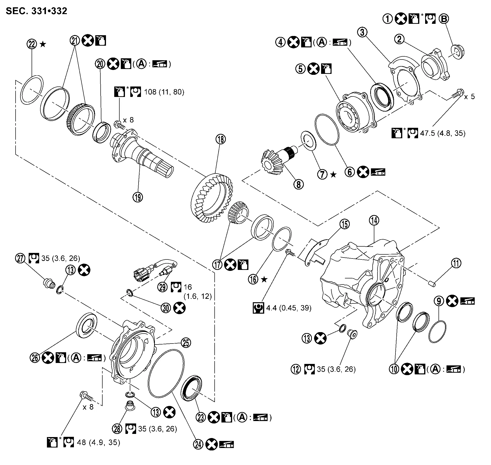
| 1. | Drive pinion lock nut | 2. | Companion flange | 3. | Dust shield |
| 4. | Drive pinion oil seal | 5. | Pinion bearing assembly | 6. | O-ring |
| 7. | Drive pinion adjusting shim | 8. | Drive pinion | 9. | O-ring |
| 10. | Transfer case oil seal | 11. | Dowel pin | 12. | Plug |
| 13. | Gasket | 14. | Transfer case | 14. | Baffle plate |
| 16. | Ring gear bearing adjusting shim (transfer case side) | 17. | Ring gear bearing (transfer case side) | 18. | Ring gear |
| 19. | Ring gear shaft | 20. | Drive shaft oil seal | 21. | Ring gear bearing (transfer cover side) |
| 22. | Ring gear bearing adjusting shim (transfer cover side) | 23. | Transfer cover oil seal | 24. | O-ring |
| 25. | Transfer cover | 26. | Transfer cover dust seal | 27. | Filler plug |
| 28. | Drain plug | 29. | Transfer oil temperature sensor | 30. | Gasket |
| A | Oil seal lip | B | Comply with the assembly procedure when tightening. Refer to Disassembly and Assembly. | ŌĆö | ŌĆö |
 : N┬Ęm (kg-m, in-lb) : N┬Ęm (kg-m, in-lb) |
|||||
 : N┬Ęm (kg-m, ft-lb) : N┬Ęm (kg-m, ft-lb) |
|||||
 : Always replace after every disassembly. : Always replace after every disassembly. |
|||||
 : Select with proper thickness. : Select with proper thickness. |
|||||
 : Apply transfer oil. : Apply transfer oil. |
|||||
| *: Apply anti-corrosive oil. |
|||||
 : Apply multi-purpose grease. : Apply multi-purpose grease. |
|||||
Disassembly and Assembly
DISASSEMBLY
Remove drain plug and gasket from transfer cover, and drain gear oil.
Remove filler plug and gasket from transfer cover.
Remove transfer oil temperature sensor (1).
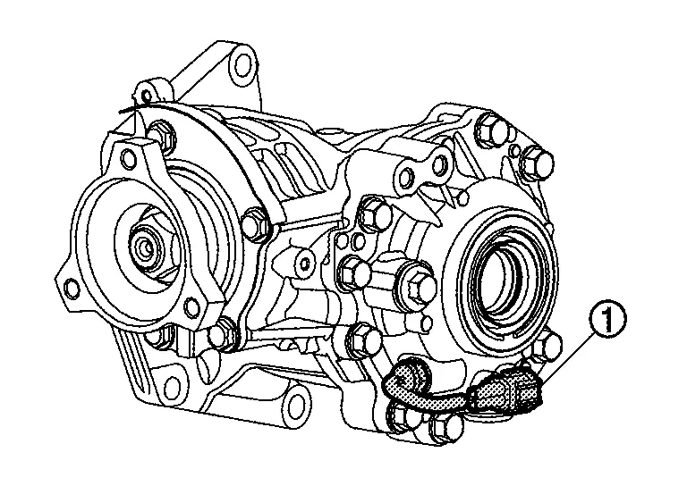
CAUTION:
-
Never subject transfer oil temperature sensor to impact by dropping or hitting it.
-
Never twists and damage the harness of transfer oil temperature sensor.
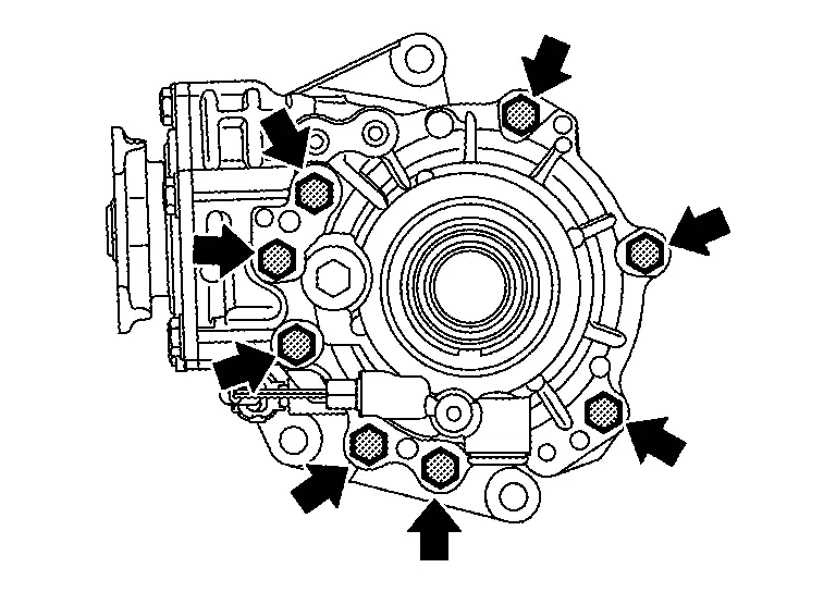
Remove transfer cover mounting bolts.
Lightly tap transfer cover (1) with a plastic hammer to remove transfer cover.
Remove O-ring from transfer cover.
CAUTION:
-
Never use a tool.
-
Never damage transfer cover.
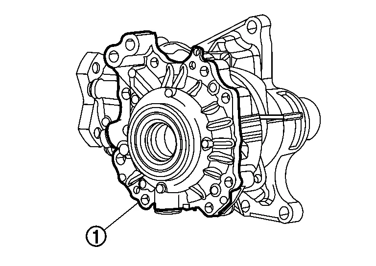
Lightly tap the metal part of oil seals (1) with pin punch etc. from back side of transfer cover to remove transfer cover oil seal and transfer cover dust seal.
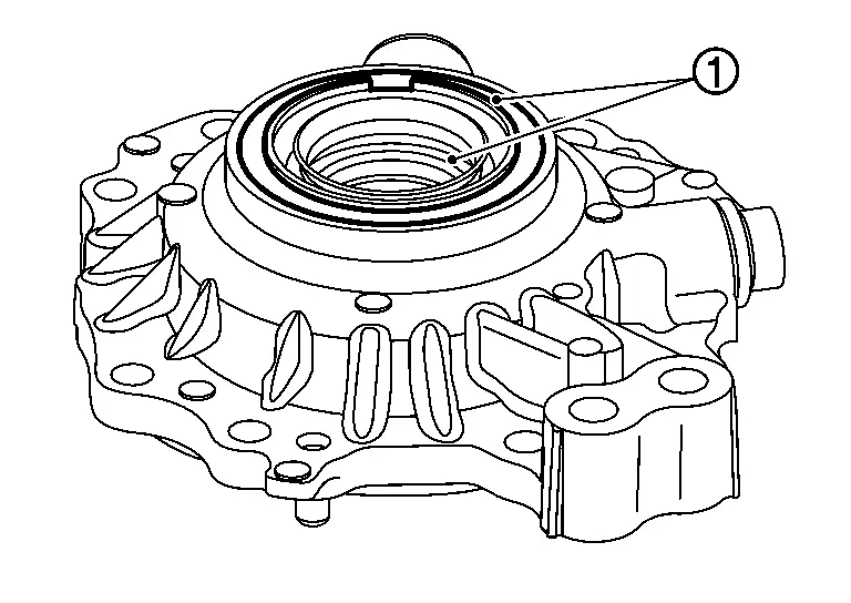
CAUTION:
When removing, never damage the transfer cover by scooping it out with a tool.
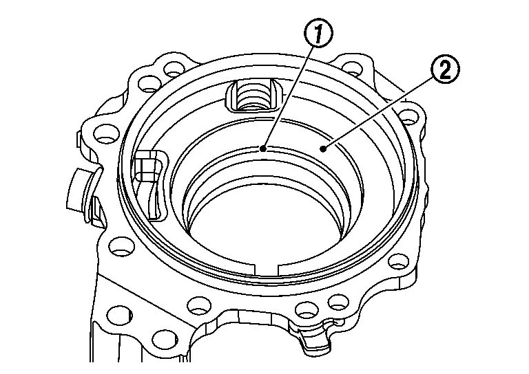
Remove ring gear bearing adjusting shim (transfer cover side) (1) and ring gear bearing outer race (transfer cover side) (2).
Perform inspection after disassembly. Refer to Inspection.
ASSEMBLY
Select the ring gear bearing adjusting shim (transfer cover side). Refer to Adjustment.
Install the selected ring gear bearing adjusting shim (transfer cover side) (1) and ring gear bearing outer race (transfer cover side) (2) using a drift (commercial service tool).
CAUTION:
-
Never reuse ring gear bearing (transfer cover side).
-
Apply transfer oil to the ring gear bearing (transfer cover side).
Install the transfer cover to the transfer case, and apply anti-corrosive oil onto thread and seats on the mounting bolts. Then tighten mounting bolts to the specified torque.
-
For tightening torque, refer to Exploded View.
 NOTE:
NOTE:
At this timing, O-ring installing to transfer cover is not necessary. Install O-ring after tooth contact is checked.
Check backlash, tooth contact, total preload and companion flange runout. Refer to Adjustment.
CAUTION:
Measure the total preload without oil seals of transfer cover and transfer case.
Remove transfer cover to install O-ring.
Install O-ring to the transfer cover.
CAUTION:
-
Never reuse O-ring.
-
Apply multi-purpose grease lightly and evenly onto O-ring.
-
When installing O-ring, never use a tool.
-
Never damage O-ring.
Install the transfer cover to the transfer case, and apply anti-corrosive oil onto thread and seats on the mounting bolts. Then tighten mounting bolts to the specified torque.
-
For tightening torque, refer to Exploded View.
Using drift (commercial service tool), install transfer cover oil seal and transfer cover dust seal with the directions below.
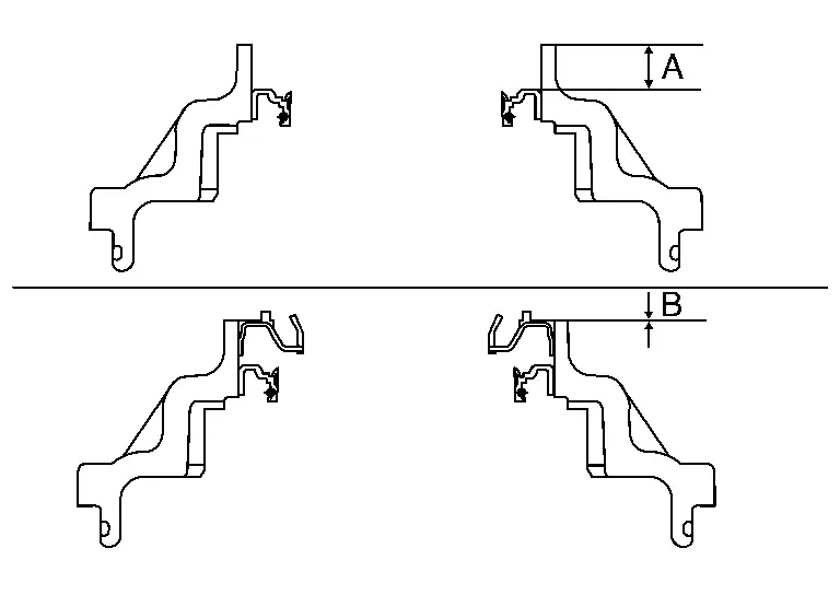
| A | : Installation dimension for transfer cover oil seal |
| B | : Installation dimension for transfer cover dust seal |
| Dimension | |
| A | : 10.3 +0.6/-0 mm (0.406 +0.024/-0 in) |
| B | : 0 +0.6/-0 mm (0 +0.024/-0 in) |
NOTE:
The positive value is deeper than the transfer cover end face.
CAUTION:
-
When checking the total preload torque, measure it without the oil seal, then install the oil seal.
-
Never reuse the oil seal.
-
When installing, never incline oil seal.
-
Apply multi-purpose grease onto oil seal lips, and transfer oil onto the circumference of oil seal.
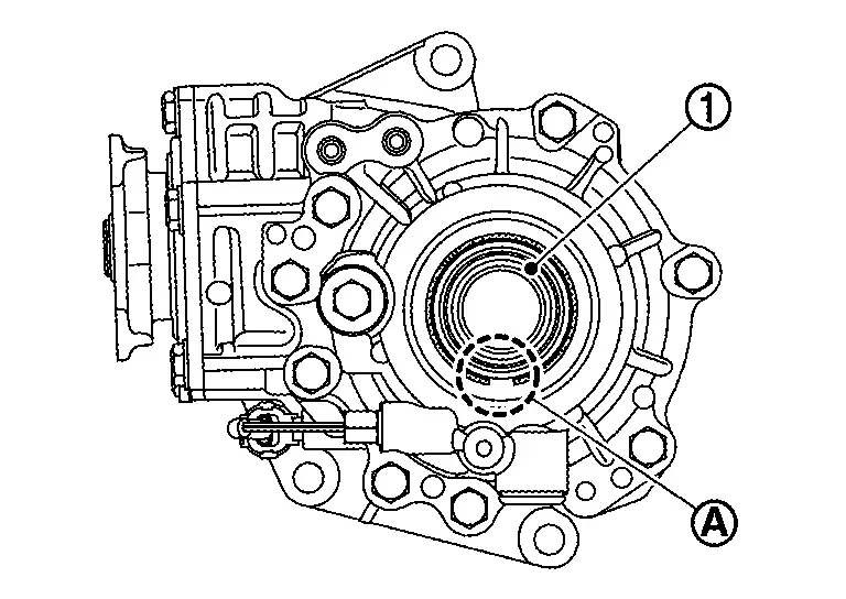
-
When installing the outer oil seal (1), the notch (A) is located on the lower side.
Install gasket onto transfer oil temperature sensor (1) and install them to transfer cover.
-
For tightening torque, refer to Exploded View.
CAUTION:
-
Never reuse gasket.
-
Never twists and damage the harness of transfer oil temperature sensor.
-
If transfer oil temperature sensor is subjected to impact by dropping or hitting it, replace with new one.
-
Be sure to dry the sensor thread before installation.
Install gasket onto drain plug and install them to transfer cover.
-
For tightening torque, refer to Exploded View.
CAUTION:
Never reuse gasket.
Install gasket onto filler plug and install them to transfer cover.
-
For tightening torque, refer to Exploded View.
CAUTION:
-
Never reuse gasket.
-
Install filler plug after oil is filled.
Inspection
INSPECTION AFTER DISASSEMBLY
Check items below. If necessary, replace them with new ones.
Transfer cover
Check the bearing mounting surface for wear, cracks and damages.
Other materials:
Dtc/circuit Diagnosis. Rear Window Defogger Switch
Component Function Check
CHECK REAR WINDOW DEFOGGER SWITCH FUNCTION
Check that the indicator lamp of rear window defogger illuminates when rear window defogger switch ON.
Is the inspection result normal?
YES>>
Rear window defogger switch function is OK.
NO>>
Refer to Diagnosis P ...
Kr15ddt. Symptom Diagnosis
Heater and Air Conditioning System Symptoms
Symptom Table
SYMPTOM TABLE Symptom Reference Page
A/C system does not come on.
Go to Trouble Diagnosis Procedure for A/C System.
Refer to Diagnosis Procedure (with automatic air
conditioning system) or Diagnosis Procedure (with manual air
...
Fuel Pump Control Module
Component Inspection
CHECK FUEL PUMP CONTROL MODULE (FPCM)
Check the voltage between FPCM terminals under the following conditions.
FPCM Condition
Voltage
(Approx.)
Connector + ŌłÆ
Terminal
B97
6
5
For 1 second after turning ignition switch ON
9.9 V
More than ...