Nissan Rogue (T33) 2021-Present Service Manual: Drive Pinion
Kr15ddt
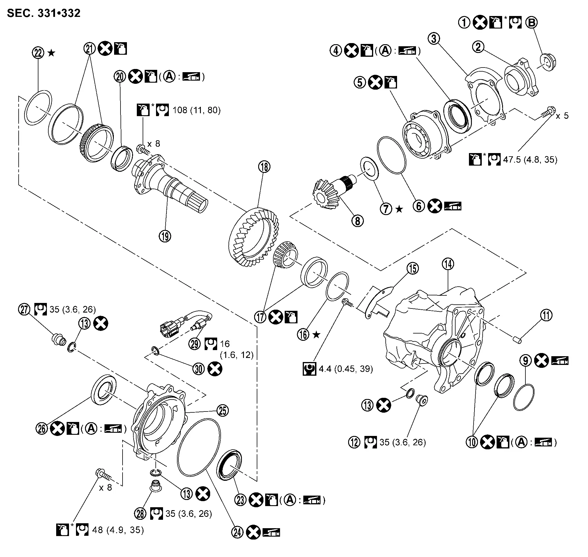
Exploded View
 |
Drive pinion lock nut |  |
Companion flange |  |
Dust shield |
 |
Drive pinion oil seal |  |
Pinion bearing assembly |  |
O-ring |
 |
Drive pinion adjusting shim |  |
Drive pinion |  |
O-ring |
 |
Transfer case oil seal |  |
Dowel pin |  |
Plug |
 |
Gasket |  |
Transfer case |  |
Baffle plate |
 |
Ring gear bearing adjusting shim (transfer case side) |  |
Ring gear bearing (transfer case side) |  |
Ring gear |
 |
Ring gear shaft |  |
Drive shaft oil seal |  |
Ring gear bearing (transfer cover side) |
 |
Ring gear bearing adjusting shim (transfer cover side) |  |
Transfer cover oil seal |  |
O-ring |
 |
Transfer cover |  |
Transfer cover dust seal |  |
Filler plug |
 |
Drain plug |  |
Transfer oil temperature sensor |  |
Gasket |
 |
Oil seal lip |  |
Comply with the assembly procedure when tightening. Refer to Disassembly and Assembly. | ||
 : N·m (kg-m, in-lb) : N·m (kg-m, in-lb) |
|||||
 : N·m (kg-m, ft-lb) : N·m (kg-m, ft-lb) |
|||||
 : Always replace after every disassembly. : Always replace after every disassembly. |
|||||
 : Select with proper thickness. : Select with proper thickness. |
|||||
 : Apply transfer oil. : Apply transfer oil. |
|||||
| *: Apply anti-corrosive oil. |
|||||
 : Apply multi-purpose grease. : Apply multi-purpose grease. |
|||||
Disassembly and Assembly
DISASSEMBLY
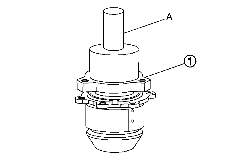
Remove pinion bearing assembly mounting bolts.
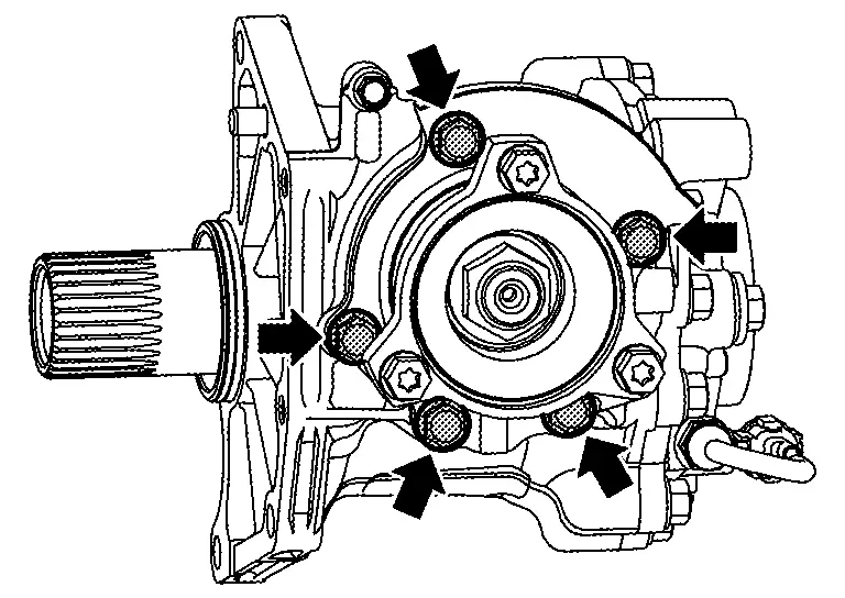
Lightly tap companion flange with a plastic hammer to remove pinion bearing assembly .
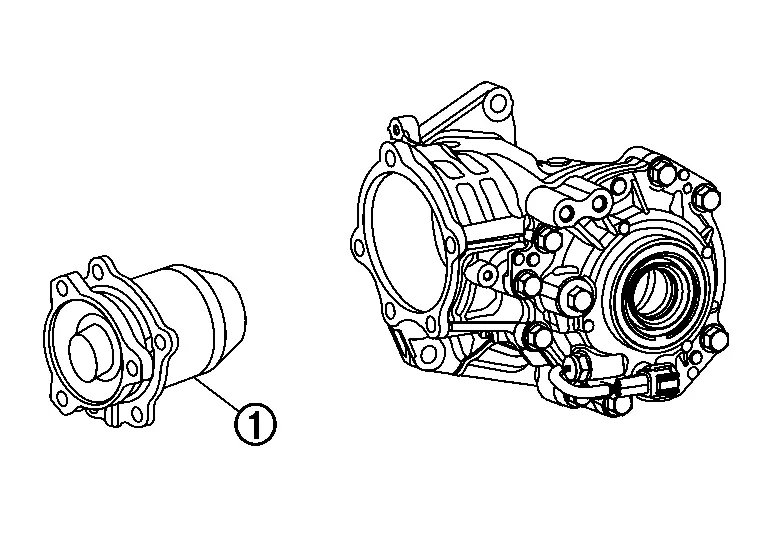
Remove the O-ring from pinion bearing assembly.
While holding companion flange with the flange wrench (commercial service tool), remove drive pinion lock nut.
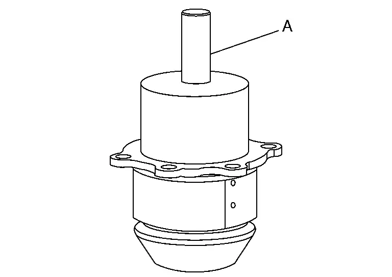
Remove drive pinion from pinion bearing assembly using drift (A) (commercial service tool) and separator (B) (commercial service tool).
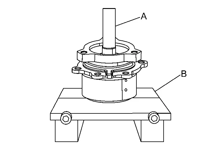
Remove drive pinion adjusting shim.
Remove companion flange.
Remove dust shield.
Remove drive pinion oil seal.
Perform inspection after disassembly. Refer to Inspection.
ASSEMBLY
Select drive pinion adjusting shim. Refer to Adjustment.
Assemble the selected drive pinion adjusting shim to drive pinion.
Install the drive pinion to pinion bearing assembly using drift (commercial service tool).
CAUTION:
-
Never reuse pinion bearing assembly.
-
Apply transfer oil to pinion bearing part.
Install drive pinion oil seal to pinion bearing assembly using drift (A) (commercial service tool).
CAUTION:
-
Never reuse the oil seal.
-
When installing, never incline oil seal.
-
Apply multi-purpose grease onto oil seal lips, and transfer oil onto the circumference of the oil seal.
Install dust shield.
 NOTE:
NOTE:
Tighten dust shield together with pinion bearing assembly.
Install companion flange to pinion bearing using drift (A) (commercial service tool).
While holding companion flange with the flange wrench (commercial service tool), tighten drive pinion lock nut within the limits of specified torque so as to keep the pinion bearing preload within the standard values.Apply anti-corrosive oil to the thread and seat of drive pinion lock nut and install it to drive pinion, and then tighten to the specified torque.
| Drive pinion lock nut tightening torque | : 90±9 N·m (9.2±0.92kg-m, 66±7 ft-lb) |
CAUTION:
-
Never reuse drive pinion lock nut.
-
Check that drive pinion lock nut is seated on the companion flange.
| Drive pinion lock nut tightening angle | : 25 degrees |
| Pinion bearing preload | : Refer to Preload Torque. |
Install O-ring to pinion bearing assembly.
CAUTION:
-
Never reuse O-ring.
-
Apply multi-purpose grease lightly and evenly onto O-ring.
-
When installing O-ring, never use a tool.
-
Never damage O-ring.
Install pinion bearing assembly, and apply anti-corrosive oil onto thread and seats on the mounting bolts. Tighten to the specified torque.
-
For tightening torque, refer to Exploded View.
NOTE:
Tighten dust shield together with pinion bearing assembly.
Check backlash, tooth contact, total preload and companion flange runout. Refer to Adjustment.
CAUTION:
Measure the total preload without oil seals of transfer cover and transfer case.
Adjustment
ADJUSTING SHIM SELECTION
Measurement point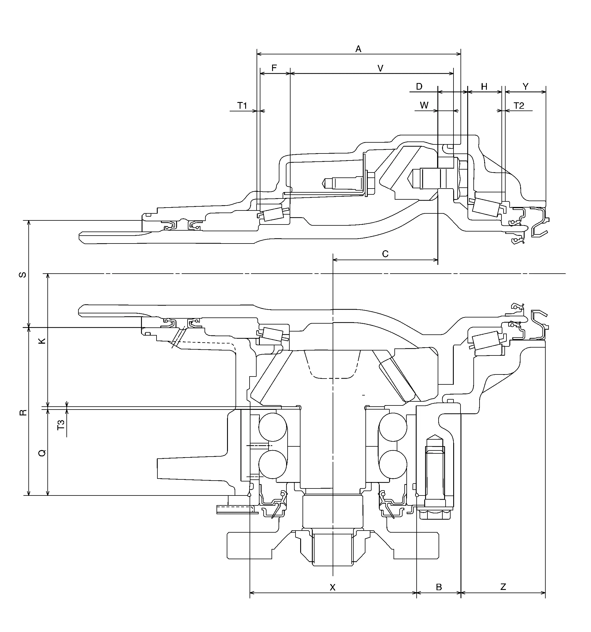
Select adjusting shim of T1, T2, and T3, respectively, by using the following equation.
T1 [Ring gear bearing adjusting shim (transfer case side)]
-
T1 = A ‚àí(B +X/2) +C +W ‚àíV ‚àíF ‚àí(M/100) +0.071 mm (0.0028 in)
T2 [Ring gear bearing adjusting shim (transfer cover side)]
-
T2 = ‚àíY +Z +(B +X/2) ‚àíC ‚àíD ‚àíH +(M/100) +0.071 mm (0.0028 in)
T3 (Drive pinion adjusting shim)
-
T3 = ‚àíQ +(R +S/2) ‚àíK +(O/100)
-
Check dimension (M) on the ring gear side face.
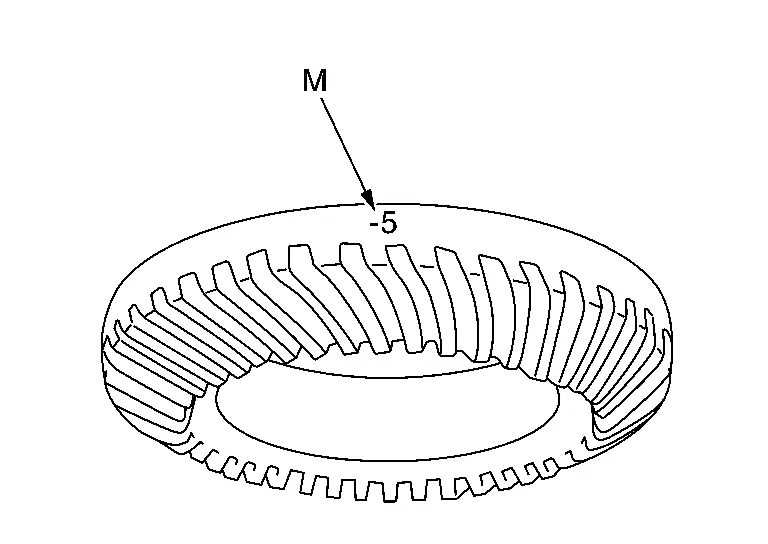 NOTE:
NOTE:
Dimension “M” indicates the difference between the optimum engagement and standard dimensions in increments of 0.01 mm (0.0004 in) written on the ring gear side face.
-
Check dimension (O) on the gear end of drive pinion.
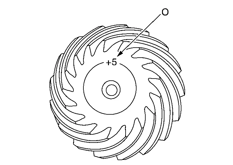 NOTE:
NOTE:
Dimension “O” indicates the difference between the optimum engagement and the standard dimensions in increments of 0.01 mm (0.0004 in) written on the gear end of drive pinion.
PINION BEARING PRELOAD
Remove ring gear shaft assembly from the transfer case. Refer to Disassembly and Assembly.
Rotate the companion flange back and forth from 2 to 3 times to check for unusual noise, binding, sticking, and so on.
Rotate the companion flange at least 20 times to check for smooth operation of the bearing.
While rotate drive pinion at 30 rpm, measure the pinion bearing preload with the preload gauge [SST: ST3127S000 (NI-25765-A)].
| Pinion bearing preload | : Refer to Preload Torque. |
CAUTION:
Each rotational part should rotate smoothly with the specified transfer oil.
NOTE:
Preload torque differs before disassembly and after reassembly. (It differ after driving and new parts.)
-
If outside the standard, disassemble pinion bearing assembly to check and adjust each part.
TOTAL PRELOAD
Measure pinion bearing preload.
CAUTION:
Check that the pinion bearing preload is within the standard.
Assemble the ring gear shaft assembly to the transfer case. Refer to Disassembly and Assembly
Install transfer cover to check and adjust each part. Refer to Disassembly and Assembly.
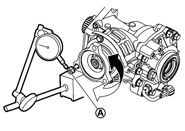
Rotate the companion flange at least 20 times to check for smooth operation of the bearing.
While rotate drive pinion at 30 rpm, measure the total preload with the preload gauge (A) [SST: ST3127S000 (NI-25765-A)].
| Total preload | : Refer to Preload Torque. |
CAUTION:
Each rotational part should rotate smoothly with the specified transfer oil.
NOTE:
Preload torque differs before disassembly and after reassembly. (It differ after driving and new parts.)
-
If outside the standard, disassemble the transfer assembly to check and adjust each part. Measure it with the transfer case oil seals and transfer cover oil seal and transfer cover dust seal removed when measuring total preload after disassembly. Then install transfer case oil seals and transfer cover oil seal and transfer cover dust seal.
BACKLASH
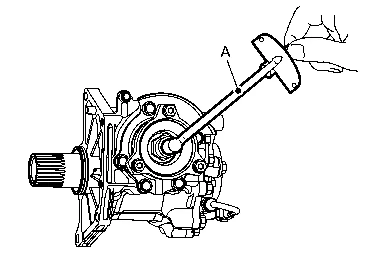
Install the suitable bolt to the companion flange.
Fit a dial indicator onto the suitable bolt .
Measure the circumference backlash of the companion flange.
| Backlash | : Refer to Backlash. |
NOTE:
Backlash differs before disassembly and after reassembly. (It differ after driving and new parts.)
-
If outside the standard, disassemble the transfer assembly to check and adjust each part.
TOOTH CONTACT
Remove transfer cover. Refer to Disassembly and Assembly.
Remove ring gear shaft assembly from transfer case. Refer to Disassembly and Assembly.
Apply red lead or equivalent onto the ring gear.
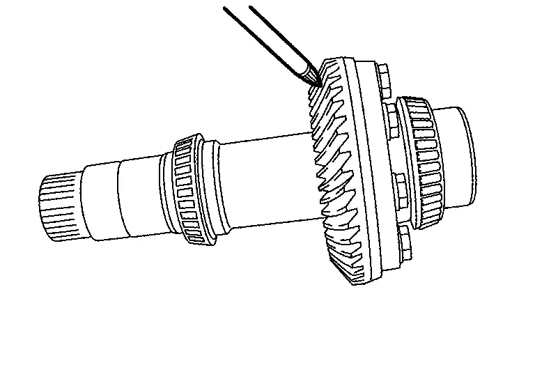
CAUTION:
Apply red lead or equivalent to both faces of 3 to 4 gears at 4 locations evenly spaced on the ring gear.
Assemble ring gear shaft assembly to the transfer case. Refer to Disassembly and Assembly.
Install transfer cover to check and adjust each part. Refer to Disassembly and Assembly.
NOTE:
At this timing, O-ring installing to transfer cover is not necessary. Install O-ring after backlash and tooth contact are checked.
Remove plug from the transfer case.
Rotate the companion flange back and forth several times, and check the drive pinion gear to ring gear tooth contact by viewing from the plug hole.
Tooth Contact Judgment Guide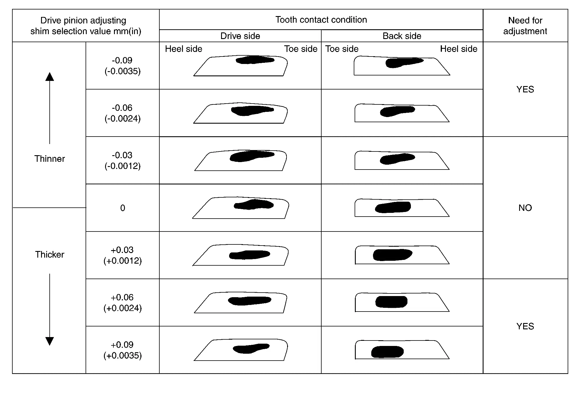
Follow the procedure below to adjust pinion height (dimension X) if tooth contact is improper.
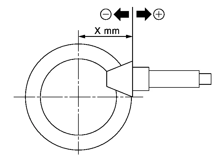
CAUTION:
If no adjusting shim with the calculated value is available, select the thicker and closest one.
-
Thicken the drive pinion adjusting shim to move the drive pinion closer to the ring gear in case of face contact or heel contact.
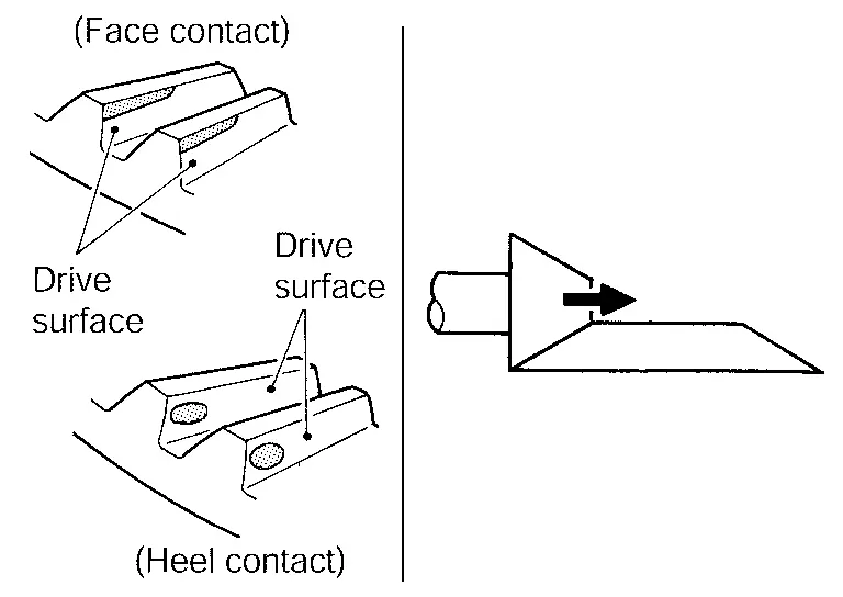
For selecting adjusting shim, refer to the latest parts information.
CAUTION:
Only one adjusting shim can be selected.
-
Thin the drive pinion adjusting shim to move the drive pinion farther from the ring gear in case of flank contact or toe contact.
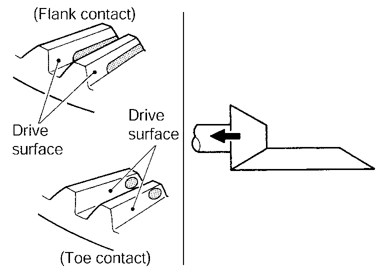
For selecting adjusting shim, refer to the latest parts information.
CAUTION:
Only one adjusting shim can be selected.
COMPANION FLANGE RUNOUT
Fit a dial indicator onto the companion flange face (inner side of the propeller shaft mounting bolt holes).
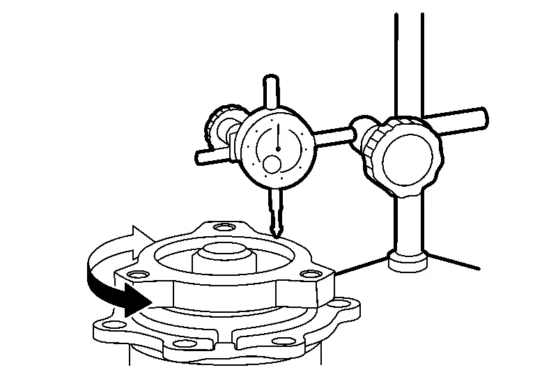
Rotate companion flange to check for runout.
| Companion flange face runout | : Refer to Companion Flange Runout. |
Fit a test indicator to the inner side of companion flange (socket diameter).
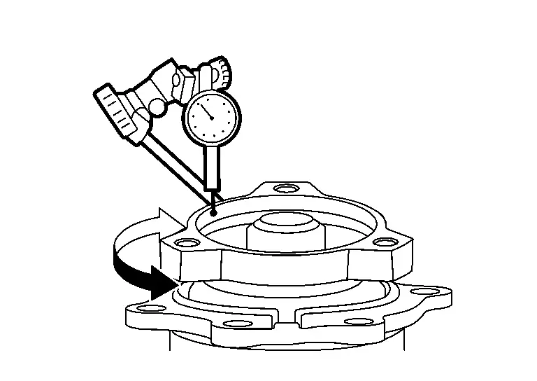
Rotate companion flange to check for runout.
| Inner side of the companion flange runout | : Refer to Companion Flange Runout. |
If the runout value is outside the runout limit, follow the procedure below to adjust.Check for runout while changing the phase between companion flange and drive pinion in 90° steps. Then search for the minimum point. Replace companion flange if runout value is still outside the limit after the phase has been changed. Adjust assembly status of the pinion bearing assembly and drive pinion, or replace pinion bearing assembly if runout is outside the standard after the companion flange is replaced.
Inspection
INSPECTION AFTER DISASSEMBLY
Check items below. If necessary, replace them with new ones.
Gear and Shaft
Check gear face and shaft for wear, cracks, damage, and seizure.
CAUTION:
Replace ring gear and drive pinion as a set (hypoid gear set) if any malfunction is detected on the ring gear or drive pinion.
Bearing
Check for seizure, peeling, wear, corrosion, sticking, unusual noise, roughness in hand turning, and other damage.
Shim
Check for seizure, damage, and unusual wear.
Other materials:
Informations de base et fonctionnement
Exemple d'affichage dynamique
L’affichage tête haute (Head-Up Display ou HUD) du Nissan Rogue est une technologie de pointe conçue pour projeter les données de conduite essentielles directement dans votre champ de vision. Cette innovation permet au conducteur du Nissan Rogue de rester co ...
Precaution. Precautions
Precaution for Supplemental Restraint System (SRS) "AIR BAG" and "SEAT BELT PRE-TENSIONER"
The Supplemental Restraint System such as “AIR BAG” and “SEAT BELT
PRE-TENSIONER”, used along with a front seat belt, helps to reduce the
risk or severity of injury to the driver and front passeng ...
Étiquette des pneus
Exemple
Informations de base
La législation fédérale impose aux fabricants de pneus d’apposer sur le flanc de chaque pneu des informations normalisées et clairement lisibles. Ces marquages, présents sur les pneus du Nissan Rogue, permettent d’identifier les caractéristiques essenti ...