Nissan Rogue (T33) 2021-Present Service Manual: Exhaust Valve Timing Intermediate Lock Control Solenoid Valve
Component Inspection
CHECK EXHAUST VALVE TIMING INTERMEDIATE LOCK CONTROL SOLENOID VALVE-1
-
Turn ignition switch OFF.
-
Disconnect exhaust valve timing intermediate lock control solenoid valve harness connector.
-
Check the resistance between exhaust valve timing intermediate lock control solenoid valve terminals as per the following.
Exhaust valve timing intermediate lock control solenoid valve Condition Resistance Terminal 1 2 Temperature 20¬ΑC (68¬ΑF) 6.7 βÄ™ 7.7 β³Π -
Check the resistance between exhaust valve timing intermediate lock control solenoid valve terminal and solenoid valve body.
Exhaust valve timing intermediate lock control solenoid valve βÄî Resistance Terminal 1 Solenoid valve body Not existed 2
Is the inspection result normal?
YES>>GO TO 2.
NO>>Replace exhaust valve timing intermediate lock control solenoid valve. Refer to Exploded View.
CHECK EXHAUST VALVE TIMING INTERMEDIATE LOCK CONTROL SOLENOID VALVE-2
-
Remove exhaust valve timing intermediate lock control solenoid valve. Refer to Exploded View.
-
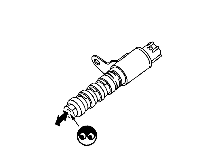
Provide battery voltage between exhaust valve timing intermediate lock control solenoid valve terminals 1 and 2, and then interrupt it. Check that the plunger moves as shown in the figure.
CAUTION:
Do not apply battery voltage continuously for 5 seconds or more. Doing so may result in damage to the coil in exhaust valve timing intermediate lock control solenoid valve.
 NOTE:
NOTE:
Always replace O-ring when exhaust valve timing intermediate lock control solenoid valve is removed.
Is the inspection result normal?
YES>>INSPECTION END
NO>>Replace exhaust valve timing intermediate lock control solenoid valve. Refer to Exploded View.
Other materials:
Fuel Pump Control Module
Component Inspection
CHECK FUEL PUMP CONTROL MODULE (FPCM)
Check the voltage between FPCM terminals under the following conditions.
FPCM Condition
Voltage
(Approx.)
Connector + βà£
Terminal
B97
6
5
For 1 second after turning ignition switch ON
9.9 V
More than ...
Informations de base et fonctionnement
Exemple d'affichage dynamique
LβÄôaffichage tΟΣte haute (Head-Up Display ou HUD) du Nissan Rogue est une technologie de pointe conΟßue pour projeter les donnΟ©es de conduite essentielles directement dans votre champ de vision. Cette innovation permet au conducteur du Nissan Rogue de rester co ...
Adp Branch Line Circuit
Diagnosis Procedure
CHECK CONNECTOR
Turn the ignition switch OFF.
Disconnect the battery cable from the negative terminal.
Check the following terminals and connectors for damage, bend and loose connection (unit side and connector side).
Driver seat control unit
Harness con ...