Nissan Rogue (T33) 2021-Present Service Manual: Exhaust Valve Timing Control Solenoid Valve
Component Inspection
CHECK EXHAUST VALVE TIMING (EVT) CONTROL SOLENOID VALVE-1
-
Turn ignition switch OFF.
-
Disconnect EVT control solenoid valve harness connector.
-
Check the resistance between EVT control solenoid valve terminals as per the following.
EVT control solenoid valve Condition Resistance Terminal 1 2 Temperature 20°C (68°F) 6.7 – 7.7 Ω -
Check the resistance between EVT control solenoid valve terminal and solenoid valve body.
EVT control solenoid valve — Resistance Terminal 1 Solenoid valve body Not existed 2
Is the inspection result normal?
YES>>GO TO 2.
NO>>Replace EVT control solenoid valve. Refer to Exploded View.
CHECK EVT CONTROL SOLENOID VALVE-2
-
Remove EVT control solenoid valve. Refer to Exploded View.
-
Provide battery voltage between EVT control solenoid valve terminals 1 and 2, and then interrupt it. Check that the plunger moves as shown in the figure.
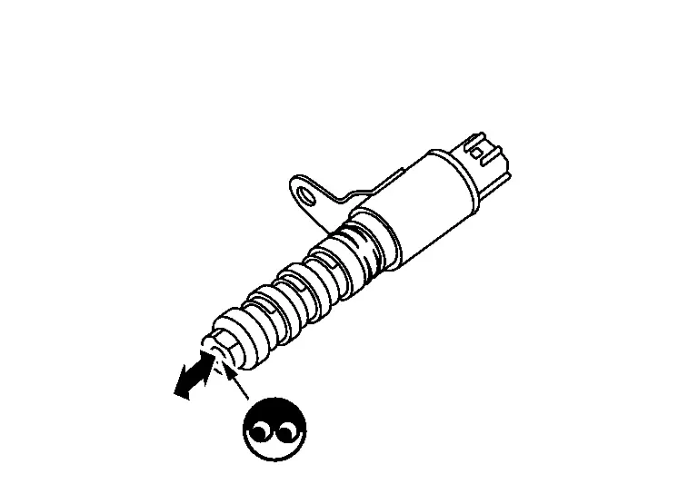
CAUTION:
Do not apply battery voltage continuously for 5 seconds or more. Doing so may result in damage to the coil in EVT control solenoid valve.
 NOTE:
NOTE:
Always replace O-ring when EVT control solenoid valve is removed.
Is the inspection result normal?
YES>>INSPECTION END
NO>>Replace EVT control solenoid valve. Refer to Exploded View.
Other materials:
Fonctionnement du système
Capteurs sonar centraux
Capteurs sonar d’angle
Capteurs sonar latéraux (si le véhicule en est équipé)
Le système informe le conducteur par des alertes visuelles et sonores de la présence :
D’obstacles situés à l’avant lorsque le levier de vitesses est en position D (c ...
B24a4-11 Intake Sensor
DTC Description
DTC DETECTION LOGIC DTC No.
CONSULT screen terms
(Trouble diagnosis content) DTC detection condition
B24A4-11
INTAKE SENSOR
(Intake sensor)
Diagnosis condition
Ignition switch ON
Signal (Terminal)
Intake sensor signal
Threshold
The intake sensor rec ...
Power Supply and Ground Circuit
Side Radar Front Lh
Diagnosis Procedure
CHECK FUSE
Check that the following fuse is not blown:
Signal name Fuse No.
Ignition power supply
9 (10 A)
Is the fuse blown?
YES>>
Replace the blown fuse after repairing the affected circuit.
NO>>
GO TO 2.
CHECK POWER SU ...