Nissan Rogue (T33) 2021-Present Service Manual: Fuel Injector
Component Function Check
INSPECTION START
Turn ignition switch to START.
Are any cylinders ignited?
YES>>GO TO 2.
NO>>Refer to Diagnosis Procedure.
CHECK FUEL INJECTOR FUNCTION
 With CONSULT
-
Start engine.
-
Perform ÔÇťPOWER BALANCEÔÇŁ in ÔÇťACTIVE TESTÔÇŁ mode of ÔÇťENGINEÔÇŁ with CONSULT.
-
Check that each circuit produces a momentary engine speed drop.
 Without CONSULT
-
Start engine and let it idle.
-
Listen to each fuel injector operating sound.
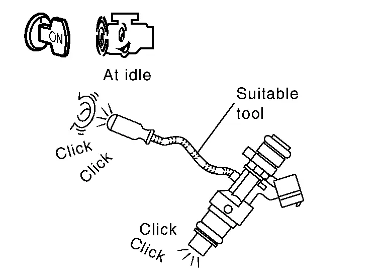
Clicking sound should be heard.
Is the inspection result normal?
YES>>INSPECTION END
NO>>Refer to Diagnosis Procedure.
Diagnosis Procedure
CHECK FUSE
-
Ignition switch OFF.
-
Check that the following fuse is not blowing.
Fuse No. Capacity #79 15 A #102 20 A
Is the fuse blown (open)?
YES>>Replace the fuse after repairing the applicable circuit.
NO>>GO TO 2.
CHECK FUEL INJECTOR DRIVER POWER SUPPLY
-
Disconnect ECM harness connector.
-
Ignition switch ON.
-
Check the voltage between ECM harness connector and ground.
+ Ôłĺ Voltage ECM Connector Terminal F72 1 Ground Battery voltage
Is the inspection result normal?
YES>>GO TO 9.
NO>>GO TO 3.
CHECK FUEL INJECTOR DRIVER POWER SUPPLY CIRCUIT
-
Ignition switch OFF.
-
Disconnect ECM harness connector.
-
Disconnect fuel injector relay harness connector.
-
Check the continuity between ECM harness connector and fuel injector relay harness connector.
ECM Fuel injector relay Continuity Connector Terminal Connector Terminal F72 1 F55 1 Existed -
Also check harness for short to ground and short to power.
Is the inspection result normal?
YES>>GO TO 4.
NO>>Repair or replace malfunctioning part.
CHECK FUEL INJECTOR RELAY POWER SUPPLY (CONTACT SIDE)
Check the voltage between fuel injector relay harness connector and ground.
| + | Ôłĺ | Voltage | |
|---|---|---|---|
| Fuel injector relay | |||
| Connector | Terminal | ||
| F55 | 2 | Ground | Battery voltage |
Is the inspection result normal?
YES>>GO TO 5.
NO>>Perform trouble diagnosis for power supply circuit.
CHECK FUEL INJECTOR RELAY POWER SUPPLY (EXCITATION COIL SIDE)
-
Install all removed parts.
-
Ignition switch ON.
-
Check the voltage between fuel injector relay harness connector and ground.
+ Ôłĺ Voltage Fuel injector relay Connector Terminal F55 4 Ground Battery voltage
Is the inspection result normal?
YES>>GO TO 7.
NO>>GO TO 6.
CHECK FUEL INJECTOR RELAY POWER SUPPLY CIRCUIT (EXCITATION COIL SIDE)
-
Ignition switch OFF.
-
Disconnect fuel injector relay harness connector.
-
Disconnect IPDM E/R harness connector.
-
Check the continuity between IPDM E/R harness connector and fuel injector relay harness connector.
IPDM E/R Fuel injector relay Continuity Connector Terminal Connector Terminal F35 73 F55 4 Existed -
Also check harness for short to ground and short to power.
Is the inspection result normal?
YES>>Perform trouble diagnosis for power supply circuit.
NO>>Repair or replace malfunctioning part.
CHECK FUEL INJECTOR RELAY GROUND CIRCUIT
-
Ignition switch OFF.
-
Disconnect fuel injector relay harness connector.
-
Check the continuity between fuel injector relay harness connector and ground.
Fuel injector relay ÔÇö Continuity Connector Terminal F55 3 Ground Existed -
Also check harness for short to power.
Is the inspection result normal?
YES>>GO TO 8.
NO>>Repair or replace malfunctioning part.
CHECK FUEL INJECTOR RELAY
Refer to Component Inspection.
Is the inspection result normal?
YES>>Check intermittent incident. Refer to Intermittent Incident.
NO>>Replace fuel injector relay.
CHECK ECM GROUND CIRCUIT
-
Ignition switch OFF.
-
Check the continuity between ECM harness connector and ground.
ECM ÔÇö Continuity Connector Terminal F72 4 Ground Existed E21 156 157 160 -
Also check harness for short to power.
Is the inspection result normal?
YES>>GO TO 10.
NO>>Repair or replace malfunctioning part.
CHECK FUEL INJECTOR GROUND CIRCUIT
-
Ignition switch OFF.
-
Disconnect ECM harness connector.
-
Check the continuity between fuel injector harness connector and ECM harness connector.
Fuel injector ECM Continuity Cylinder Connector Terminal Connector Terminal 1 F202 1 F72 9 Existed 2 17 2 F203 1 11 2 20 3 F204 1 12 2 18 -
Also check harness for short to ground.
Is the inspection result normal?
YES>>GO TO 11.
NO>>Repair or replace malfunctioning part.
CHECK FUEL INJECTOR
Refer to Component Inspection.
Is the inspection result normal?
YES>>Check intermittent incident. Refer to Intermittent Incident.
NO>>Repair or replace malfunctioning part.
Component Inspection
CHECK FUEL INJECTOR
-
Turn ignition switch OFF.
-
Disconnect fuel injector harness connector.
-
Check the resistance between fuel injector terminals.
Fuel injector Condition Resistance Terminal 1 2 Temperature [┬░C (┬░F)] 20 (68) 1.34 ÔÇô 1.64 ÔäŽ
Is the inspection result normal?
YES>>INSPECTION END
NO>>Replace fuel injector. Refer to Removal and Installation.
Other materials:
Syst├Ęme d'essuie-glace automatique avec d├ętecteur de pluie du Nissan Rogue
Le Nissan Rogue est dot├ę d'une technologie de d├ętection de pr├ęcipitations intelligente. Ce syst├Ęme d'essuie-glace automatique, assist├ę par un capteur de pluie optique situ├ę sur la partie sup├ęrieure du pare-brise (derri├Ęre le r├ętroviseur int├ęrieur), est capable d'activer les balais sa ...
Component Parts
Engine Control System
Component Parts Location
ENGINE ROOM COMPARTMENT
Right front of Nissan Ariya vehicle
Left front of vehicle
Nissan Ariya Vehicle front
IPDM E/R
ECM
Admission valve
Turbocharger boost senso ...
Component Parts
Automatic Air Conditioning System
Component Parts Location
A.
Instrument panel
B.
Left front of Nissan Ariya vehicle
C.
Right side of blower unit assembly
D.
Right side of heater and cooling unit assembly
E.
Left side of heater and cooling unit assembly
...