Nissan Rogue (T33) 2021-Present Service Manual: Removal and Installation :: Coil Spring
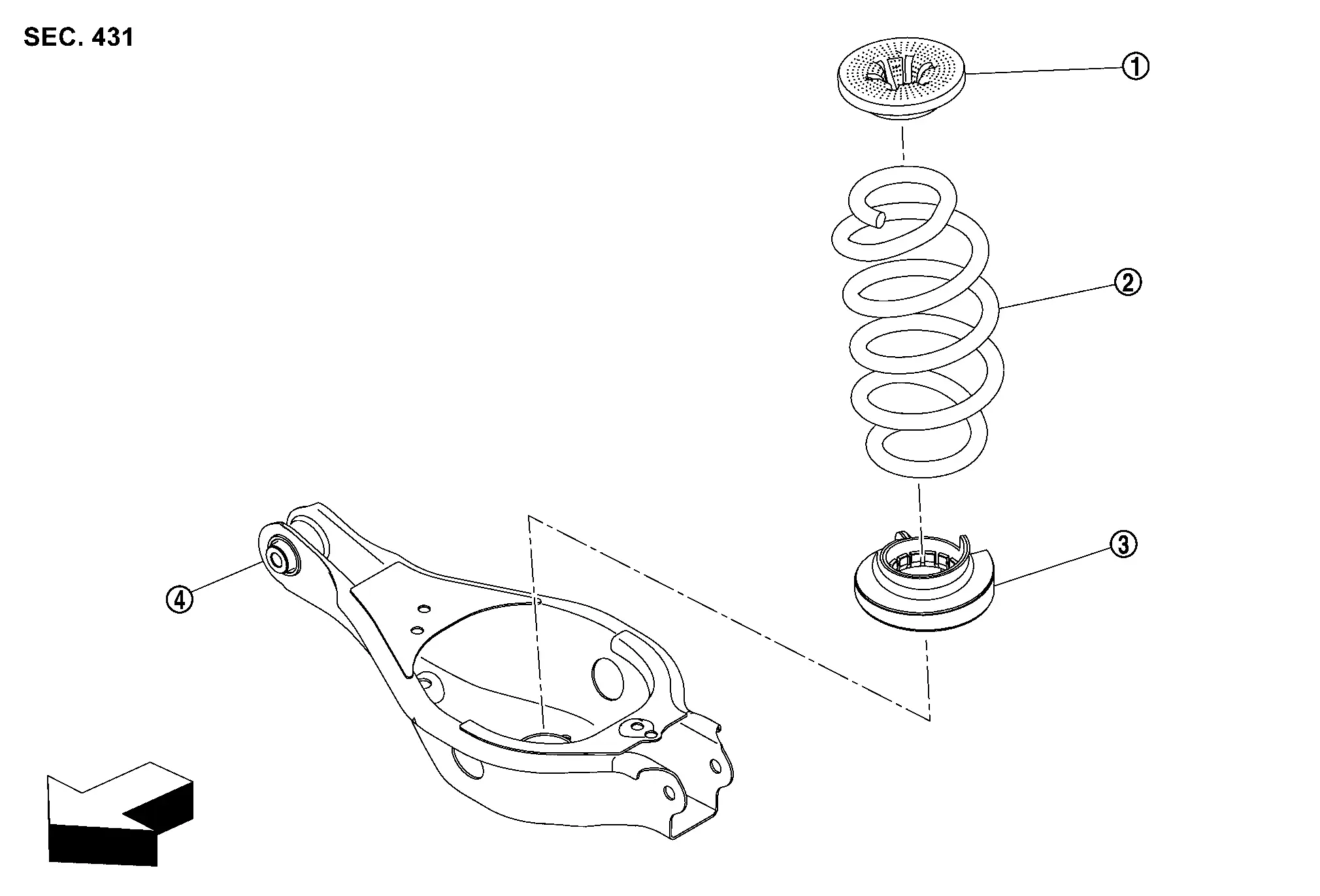
Exploded View
 |
Upper rubber seat |  |
Coil spring |  |
Lower rubber seat |
 |
Rear lower link | ||||
| : Nissan Ariya Vehicle front |
Removal and Installation
REMOVAL
Remove tires. Refer to Removal & Installation..
Using jack (A) to rear lower link .
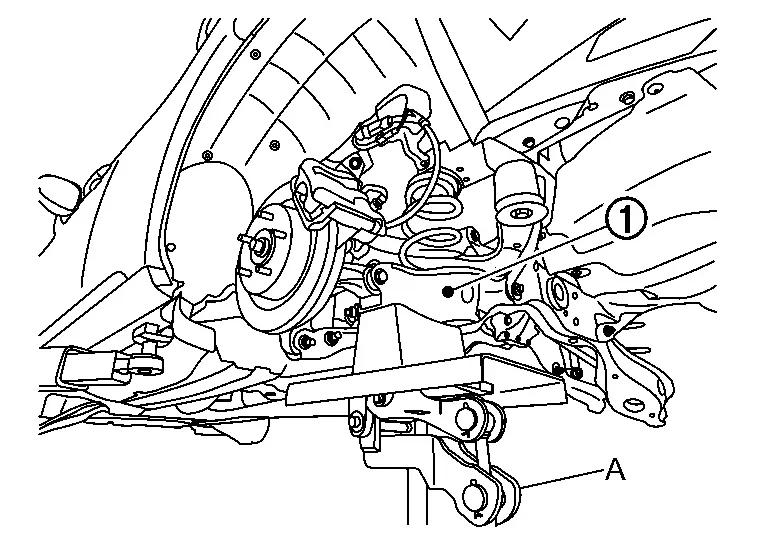
CAUTION:
-
Never damage the rear lower link with a jack.
-
Check the stable condition when using a jack.
Loosen the rear lower link mounting bolts and nuts  (rear suspension member side).
Remove the rear lower link mounting bolts and nuts (axle housing side).
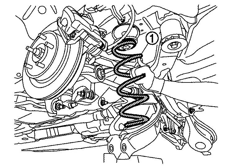
Slowly lower jack, remove upper rubber seat and coil spring .
CAUTION:
Operate while checking that jack supporting status is stable.
Remove lower rubber seat from rear lower link.
Perform inspection after removal. Refer to Inspection.
INSTALLATION
Note the following, and install in the reverse order of removal.
-
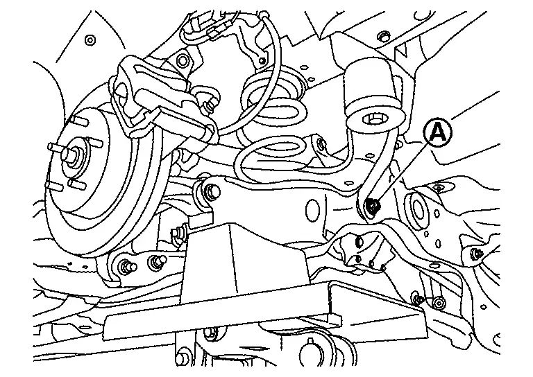
Install lower rubber seat
with its protrusion on the lower area aligned with the hole  of rear lower link.
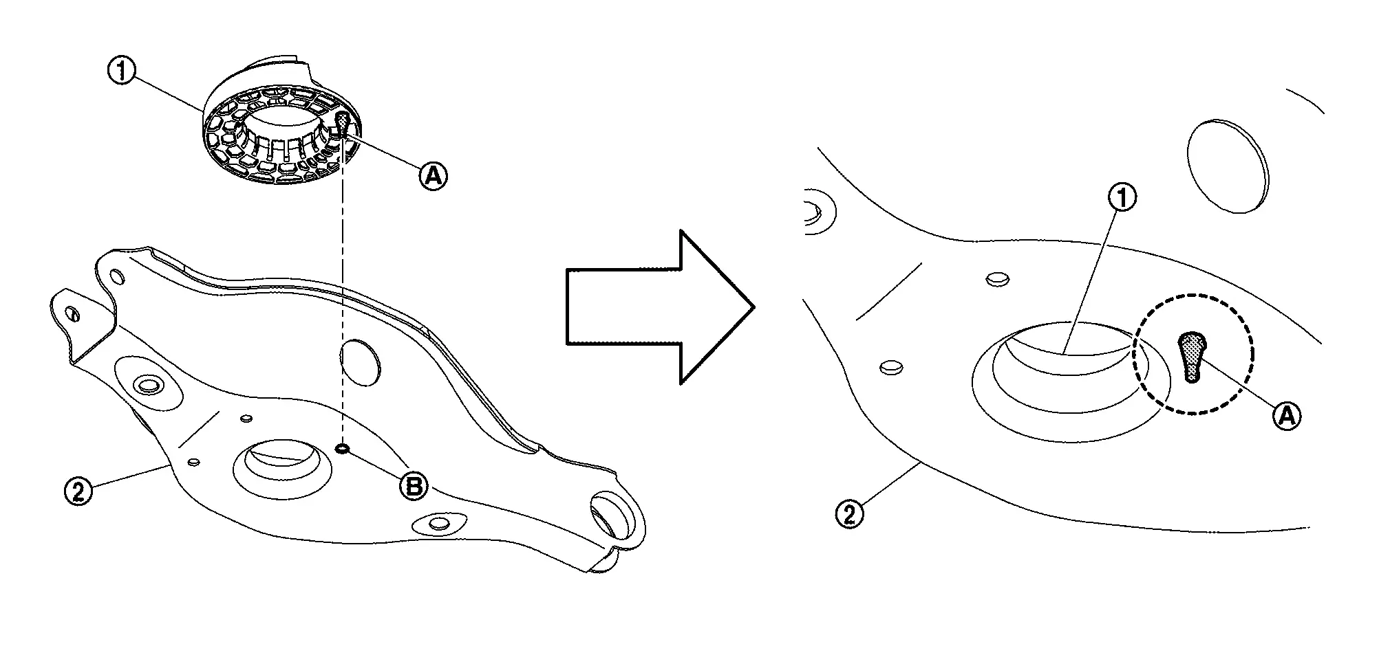
CAUTION:
The lower rubber seat protrusion
must be securely inserted into the hole of rear lower link. -
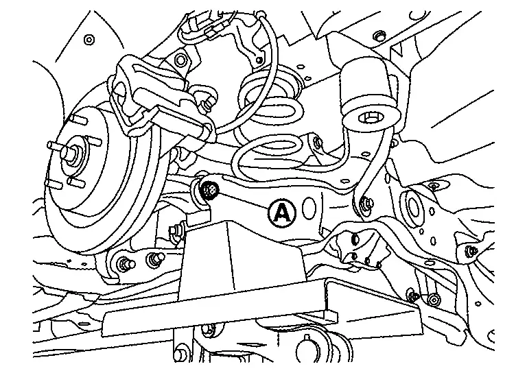
Install coil spring
by aligning lower end of coil spring with lower rubber seat as shown in the figure.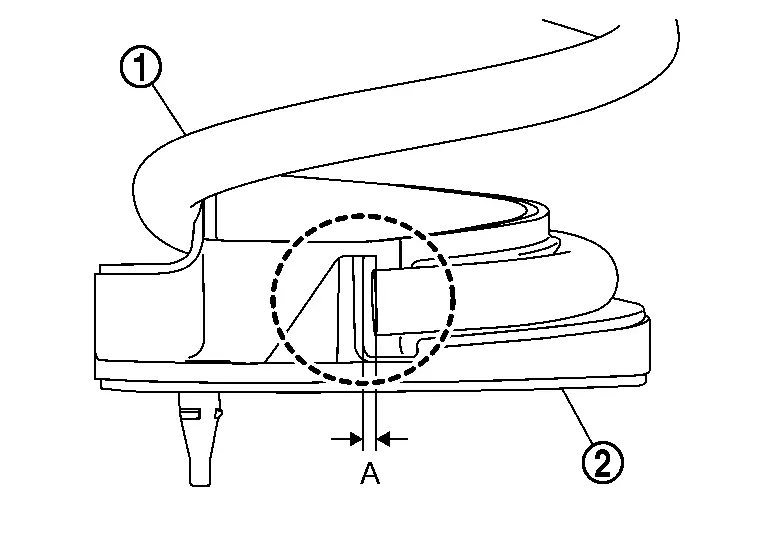
Dimension (A) : 5 mm (0.20 in) or less CAUTION:
Set coil spring so that its paint marks
and are aligned with the position from the bottom end of the coil spring shown in the figure.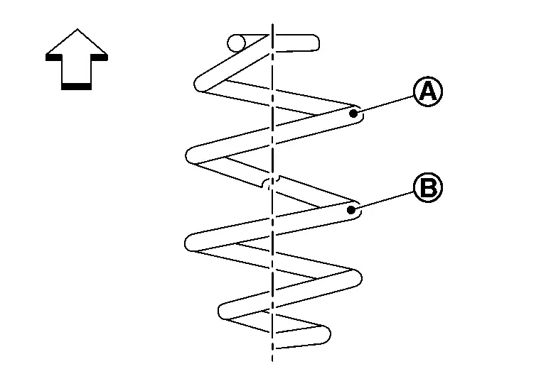

: Upper side Japan production models : 2.75 turns : 1.80 turns North America production models : 3.5 turns : 2.5 turns -
Perform final tightening of fixing parts at the Nissan Ariya vehicle installation position (rubber bushing), under unladen conditions with tires on level ground.
-
Perform inspection after installation. Refer to Inspection.
Inspection
INSPECTION AFTER REMOVAL
Check rear lower link, rubber seat, upper seat, and coil spring for deformation, crack, and damage. Replace it if necessary.
INSPECTION AFTER INSTALLATION
Check wheel alignment. Refer to Inspection.
Other materials:
Additional Service When Replacing Side Radar
Work Procedure
Always perform the side radar configuration after replacing the side radar.SIDE RADAR CONFIGURATION
Perform saving vehicle internal information according to "Replace ECU" in CONSULT Operation Manual.
>>
GO TO 2.
SIDE RADAR ALIGNMENT
Perform the side radar alignment with ...
P0053 A/f Sensor 1 Heater
DTC Description
DTC DETECTION LOGIC DTC
CONSULT screen terms
(Trouble diagnosis content)
DTC detection condition
P0053
00
HO2S1 HTR B1
(HO2S heater resistance bank 1 sensor 1)
Diagnosis condition
—
Signal (terminal)
A/F sensor 1 heater signal
Threshold
D ...
Symptom Diagnosis. Ignition Position Warning Function Does Not Operate
Diagnosis Procedure
CHECK POWER DOOR LOCK OPERATION
Check door lock/unlock using door lock/unlock switch.
Does door lock/unlock with door lock/unlock switch?
YES>>
GO TO 2.
NO>>
Refer to Diagnosis Procedure.
CHECK DOOR SWITCH
Check front door switch (front LH).
Refer to Compo ...