Nissan Rogue (T33) 2021-Present Service Manual: Removal and Installation :: Rear Shock Absorber
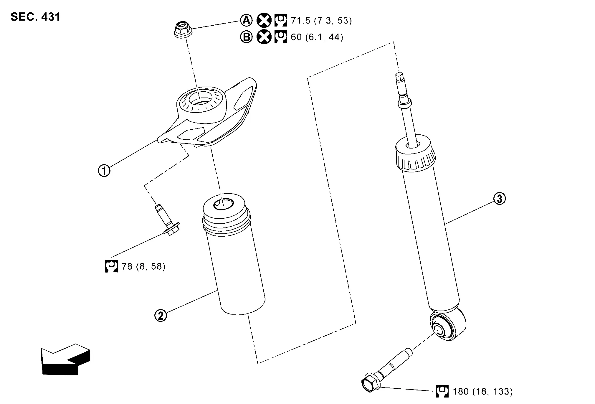
Exploded View
 |
Shock absorber mounting bracket |  |
Bound bumper |  |
Shock absorber |
 |
Japan production models |  |
North America production models | ||
| : Nissan Ariya Vehicle front | |||||
 |
: N·m (kg-m, ft-lb) | ||||
 |
: Always replace after every disassembly. | ||||
Removal and Installation
REMOVAL
Remove tires. Refer to Exploded View.
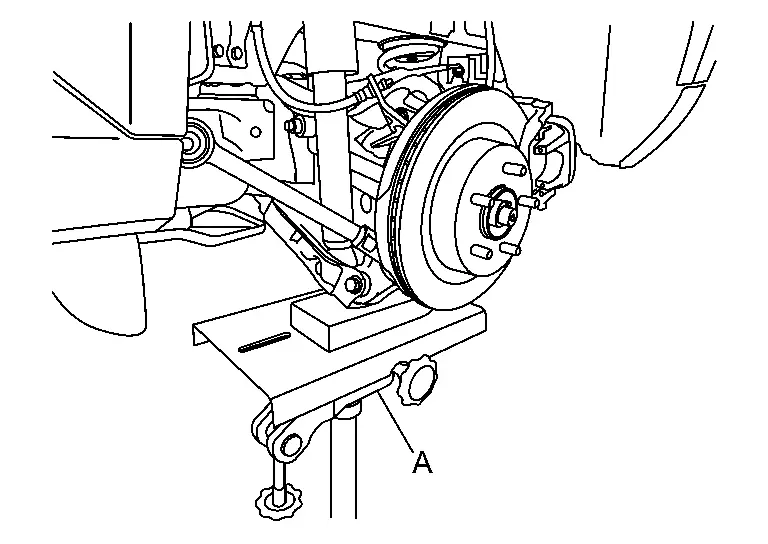
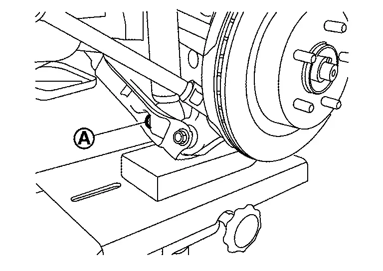
Set jack under front lower link.
CAUTION:
-
Check the stable condition when using a jack.
-
Never damage front lower link with a jack (A).
Remove shock absorber mounting bolt (lower side).
Remove shock absorber mounting bolts (Upper side).
Remove shock absorber.
Perform inspection after removal. Refer to Inspection.
INSTALLATION
Note the following, and install in the reverse order of removal.
-
Perform final tightening of fixing parts at the vehicle installation position (rubber bushing), under unladen conditions with tires on level ground.
-
Perform inspection after installation. Refer to Inspection.
-
After replacing the shock absorber, always follow the disposal procedure to discard the shock absorber. Refer to Disposal.
Disassembly and Assembly
DISASSEMBLY
Remove rear shock absorber. Refer to Removal and Installation.
Secure rear shock absorber in vice.
CAUTION:
-
Do not damage shock absorber piston rod when removing components from shock absorber.
-
Do not set the cylindrical part of the rear shock absorber in a vise.
When removing piston rod lock nut use Tool (B) to hold piston rod while using Tool (A) to loosen piston rod lock nut.
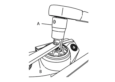
| Tool number (A) | :NI-53363 |
| Tool number (B) | :NI-53362 |
ASSEMBLY
Install dust cover onto shock absorber mounting.
Install shock absorber onto shock absorber mounting.
Use Tool (B) to hold piston rod while using Tool (A) to tighten piston rod lock nut to specification.
| Tool number (A) | :NI-53363 |
| Tool number (B) | :NI-53362 |
Remove shock absorber from vise.
CAUTION:
-
Do not damage shock absorber piston rod when removing components from shock absorber.
-
Do not set the cylindrical part of the rear shock absorber in a vise.
Inspection
INSPECTION AFTER DISASSEMBLY
Check the following items, and replace the part if necessary.
-
Shock absorber and bushing for deformation, cracks, and other damage.
-
Piston rod for damage, uneven wear, and distortion.
-
Oil leakage
INSPECTION AFTER REMOVAL
Check rear shock absorber for deformation, crack, and damage. Replace it if necessary.
INSPECTION AFTER INSTALLATION
Check wheel alignment. Refer to Inspection.
Disposal
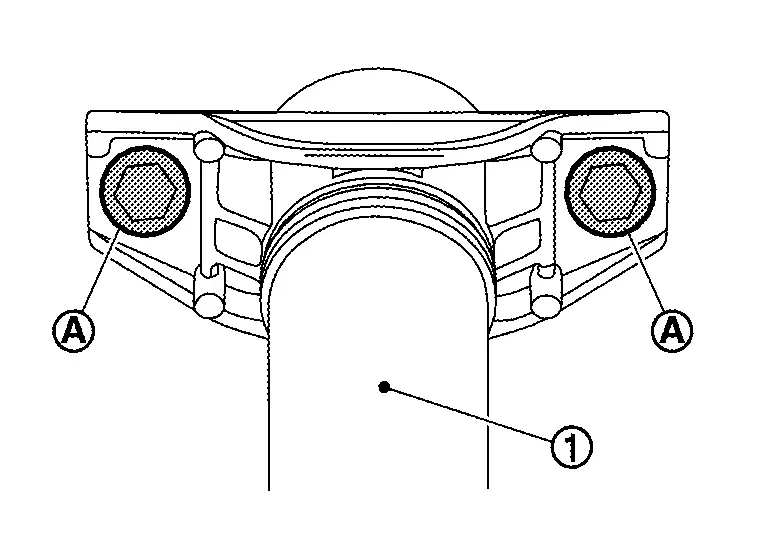
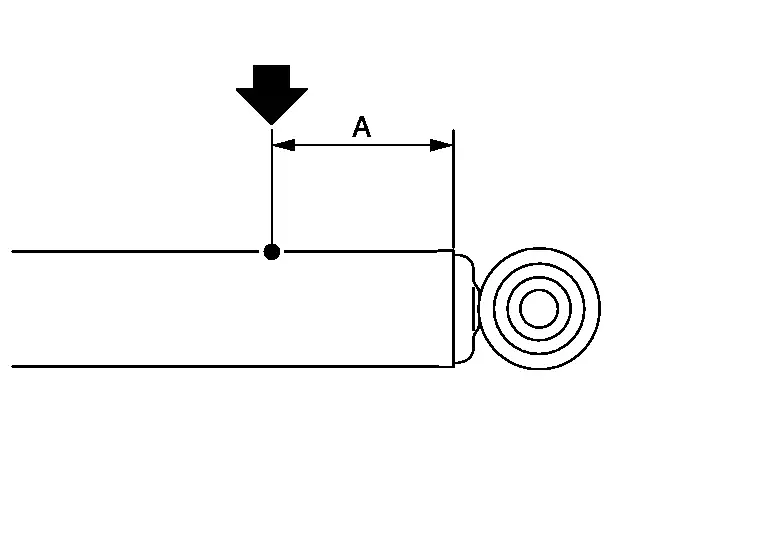
Set shock absorber horizontally to the ground with the piston rod fully extracted.
Drill 2 â 3 mm (0.08 â 0.12 in) hole at the position ( ) from top as shown in the figure to release gas gradually.
CAUTION:
-
Wear eye protection (safety glasses).
-
Wear gloves.
-
Be careful with metal chips or oil blown out by the compressed gas.
 NOTE:
NOTE:
-
Drill vertically in this direction show by arrow.
-
Directly to the outer tube avoiding brackets.
-
The gas is clear, colorless, odorless, and harmless.
| A | : 20 â 30 mm (0.79 â 1.18 in) |
Position the drilled hole downward and drain oil by moving the piston rod several times.
CAUTION:
Dispose of drained oil according to the law and local regulations.
Other materials:
Diagnosis System (hvac)
CONSULT Function
CONSULT performs the following functions via CAN communication with A/C amp. Diagnosis mode Function
Self diagnosis result
Display non-network DTC which A/C amp. memorizes
ECU identification
The A/C amp. part number is displayed
Active Test
The signals used t ...
RÃĐglages
Informations de base
Le mode de rÃĐglages permet à lâutilisateur de personnaliser les informations affichÃĐes sur lâÃĐcran dâinformations du vÃĐhicule ainsi que plusieurs paramÃĻtres de fonctionnement du Nissan Rogue. Ces rÃĐglages offrent une adaptation fine du vÃĐhicule selon vos prÃĐfÃĐre ...
Adas Control Unit. Basic Inspection
Additional Service When Replacing Adas Control Unit 2
Without Propilot Assist 2.1
Work Procedure
Always perform the additional service after replacing the ADAS control unit 2.ADAS CONTROL UNIT 2 CONFIGURATION
Perform saving Nissan Ariya vehicle internal information according to "Replace ECU" i ...