Nissan Rogue (T33) 2021-Present Service Manual: Removal and Installation :: Brake Pedal
Without Propilot Assist 2.1
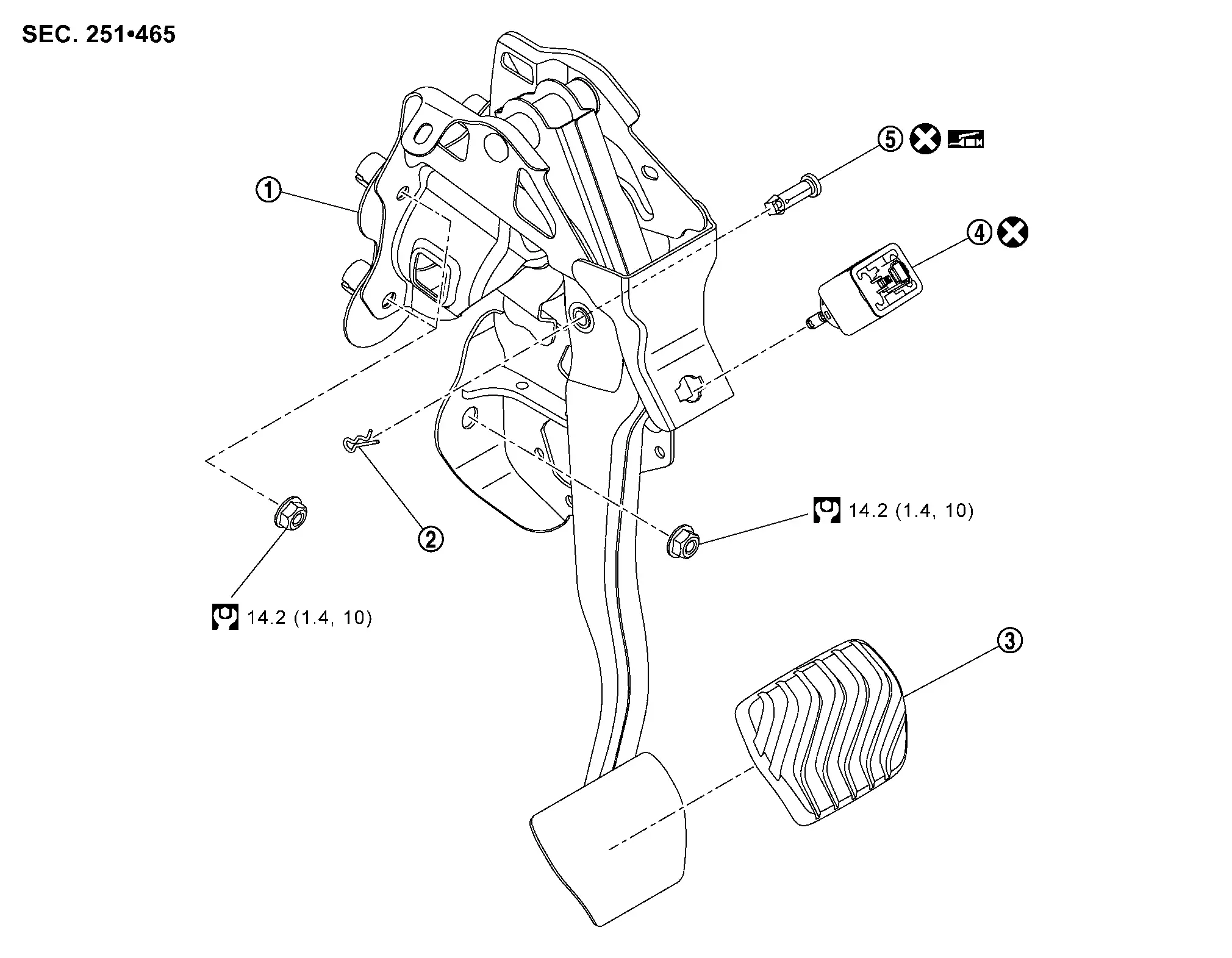
Exploded View
 |
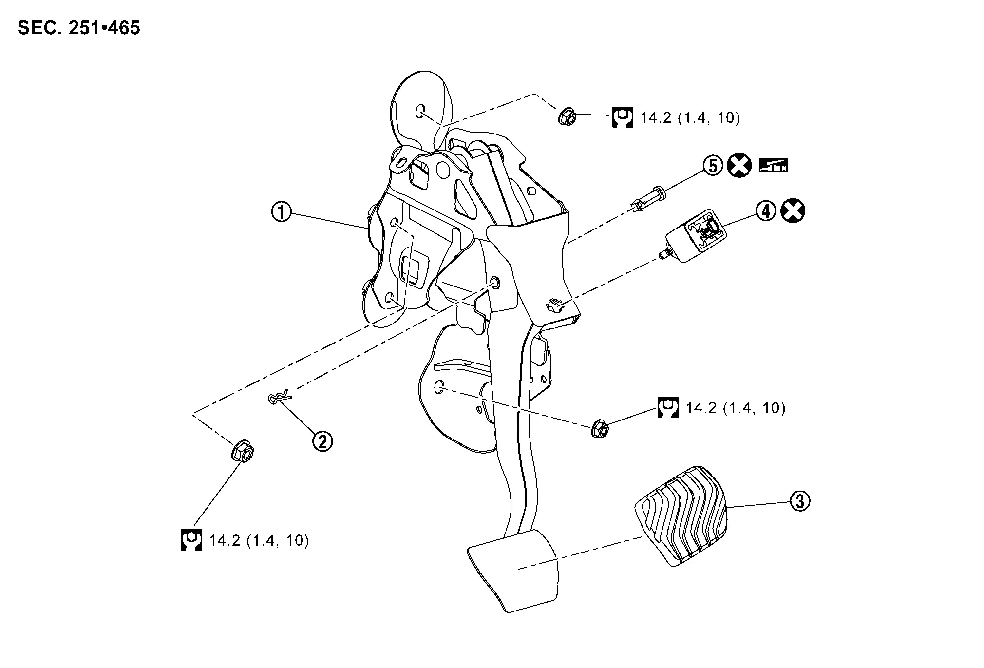
Brake pedal assembly |  |
Snap pin |  |
Brake pedal pad |
 |
Stop lamp switch |  |
Clevis pin | ||
 |
: N·m (kg-m, ft-lb) | ||||
 |
: Apply multi-purpose grease. | ||||
 |
: Always replace after every disassembly. | ||||
Removal and Installation
REMOVAL
Remove instrument lower panel LH. Refer to Removal and Installation.
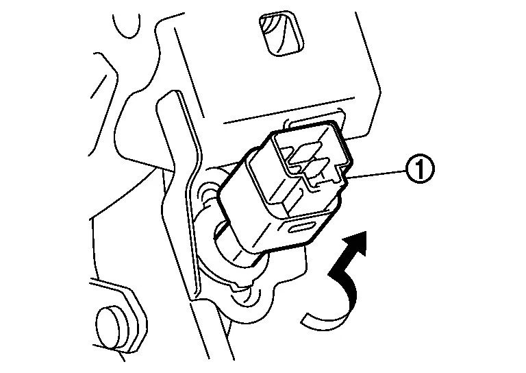
Disconnect the stop lamp switch harness connectors.
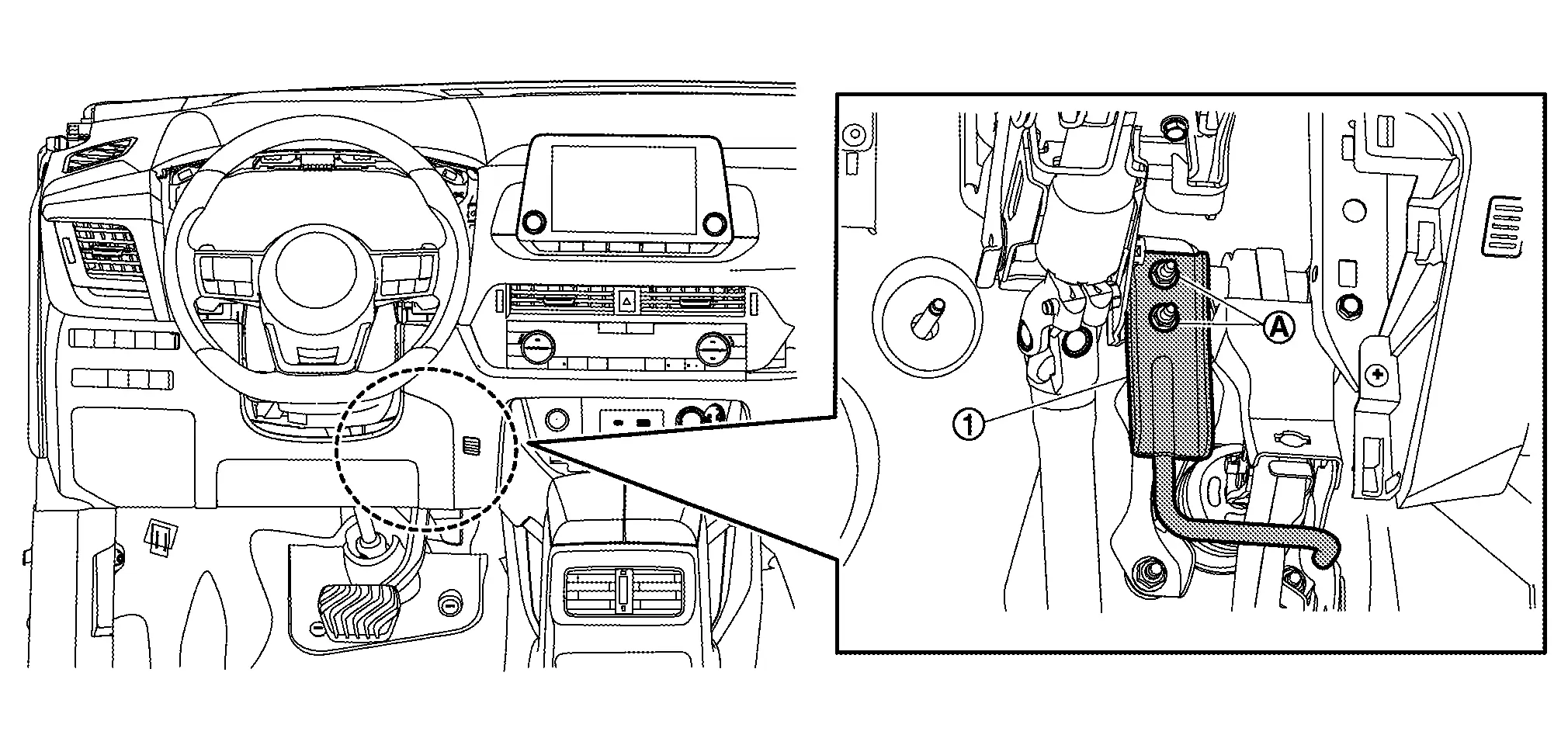
Rotate the stop lamp switch (1) counterclockwise to remove.
Disconnect the accelerator pedal harness connector.
Remove the accelerator pedal from the brake pedal assembly. Refer to Removal and Installation.
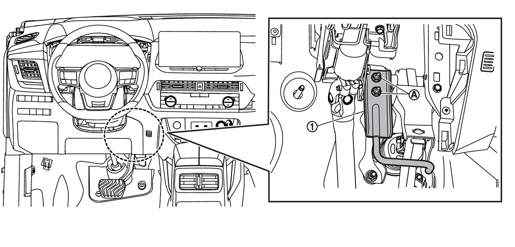
Remove nuts (A), and then remove bracket (1).
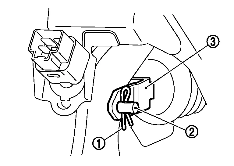
Remove snap pin (1) and clevis pin (2) from clevis of brake booster (3).
Remove harness clip from brake pedal.
Remove the brake pedal assembly.
CAUTION:
Hold the brake booster and master cylinder assembly so as not to drop out or contact them other parts.
Perform inspection after removal. Refer to Inspection and Adjustment.
INSTALLATION
Installation is in the reverse order of removal.
-
Never reuse the clevis pin.
-
Apply the multi-purpose grease to the clevis pin and the mating faces. (Not necessary if grease has been already applied)
 NOTE:
NOTE:
The clevis pin may be inserted in either direction.
-
Never impact brake pedal such as drop and interference with tools and parts.
-
Replace brake pedal when impacting brake pedal.
-
Perform adjustment after installation. Refer to Inspection and Adjustment.
Inspection and Adjustment
INSPECTION AFTER REMOVAL
Check for the following items and replace the brake pedal assembly if necessary.
-
Check rivet
 for deformation, crack, and damage.
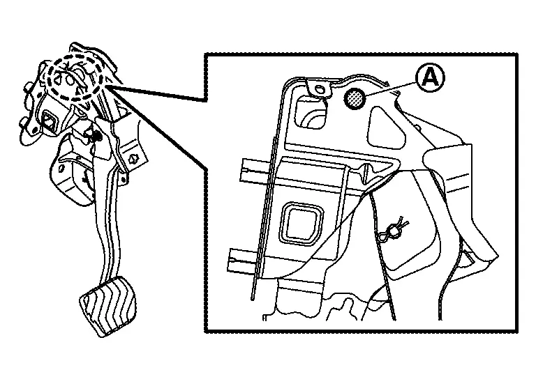
-
Check the brake pedal for bend, damage, and cracks on the welded parts.
ADJUSTMENT AFTER INSTALLATION
-
Adjust each item of brake pedal after installing the brake pedal assembly to the vehicle. Refer to Inspection and Adjustment.
-
Perform the release position learning of the accelerator pedal. Refer to Description.
With Propilot Assist 2.1
Exploded View
|
Brake pedal assembly | |
Snap pin | |
Brake pedal pad |
|
Stop lamp switch | |
Clevis pin | ||
|
: N·m (kg-m, ft-lb) | ||||
|
: Apply Nissan multi-purpose Special Grease. | ||||
|
: Always replace after every disassembly. | ||||
Removal and Installation
REMOVAL
Remove driver knee air bag module. Refer to Removal and Installation.
Disconnect the stop lamp switch harness connectors.
Rotate the stop lamp switch counterclockwise to remove.
Disconnect the accelerator pedal harness connector.
Separate the accelerator pedal from the brake pedal assembly. Refer to Removal and Installation.
Remove nuts , and then remove bracket  .
.
Remove snap pin and clevis pin from clevis of brake booster .
Remove harness clip from brake pedal.
Remove the brake pedal assembly.
CAUTION:
Hold the brake booster and master cylinder assembly so as not to drop out or contact them other parts.
Perform inspection after removal. Refer to Inspection and Adjustment.
INSTALLATION
Note the following, and install in the reverse order of removal:
-
Never reuse the clevis pin and snap pin.
-
Apply the multi-purpose grease to the clevis pin and the mating faces (Not necessary if grease has been already applied).
NOTE:
The clevis pin may be inserted in either direction.
-
Never impact brake pedal such as drop and interference with tools and parts.
-
Replace brake pedal when impacting brake pedal.
-
Perform adjustment after installation. Refer to Inspection and Adjustment.
Inspection and Adjustment
INSPECTION AFTER REMOVAL
Check for the following items and replace the brake pedal assembly if necessary:
-
Check rivet (A) for deformation, crack, and damage.
-
Check the brake pedal for bend, damage, and cracks on the welded parts.
ADJUSTMENT AFTER INSTALLATION
-
Adjust each item of brake pedal after installing the brake pedal assembly to the vehicle. Refer to Inspection and Adjustment.
-
Perform the release position learning of the accelerator pedal. Refer to Description.
Other materials:
Removal and Installation. Wind Deflector
Exploded View
Refer to Exploded View.
Removal and Installation
REMOVALFully open the glass lid.
Disengage wind deflector fixing points using a remover tool (A) from moonroof unit assembly.
Disengage wind deflector fixing pawl using a remover tool (A), and then remove wind deflector.
...
SystÃĻme 4x4 Intelligent
En cas de dysfonctionnement du systÃĻme 4x4 Intelligent du Nissan Rogue alors que le moteur est en marche, diffÃĐrents messages d'avertissement peuvent s'afficher sur l'ÃĐcran d'informations du vÃĐhicule afin d'informer le conducteur de l'ÃĐtat du systÃĻme de transmission intÃĐgrale.
Si l'a ...
Variable Compression Ratio Motor
Component Inspection
CHECK VCR MOTOR
Turn ignition switch OFF.
Disconnect VCR motor harness connector.
Check the continuity between VCR motor terminals as per the following.
VCR motor Continuity
Terminal
2
3
Existed
1
3
1
Check harness for short ...