Nissan Rogue (T33) 2021-Present Service Manual: Removal and Installation :: Emblem
Exploded view
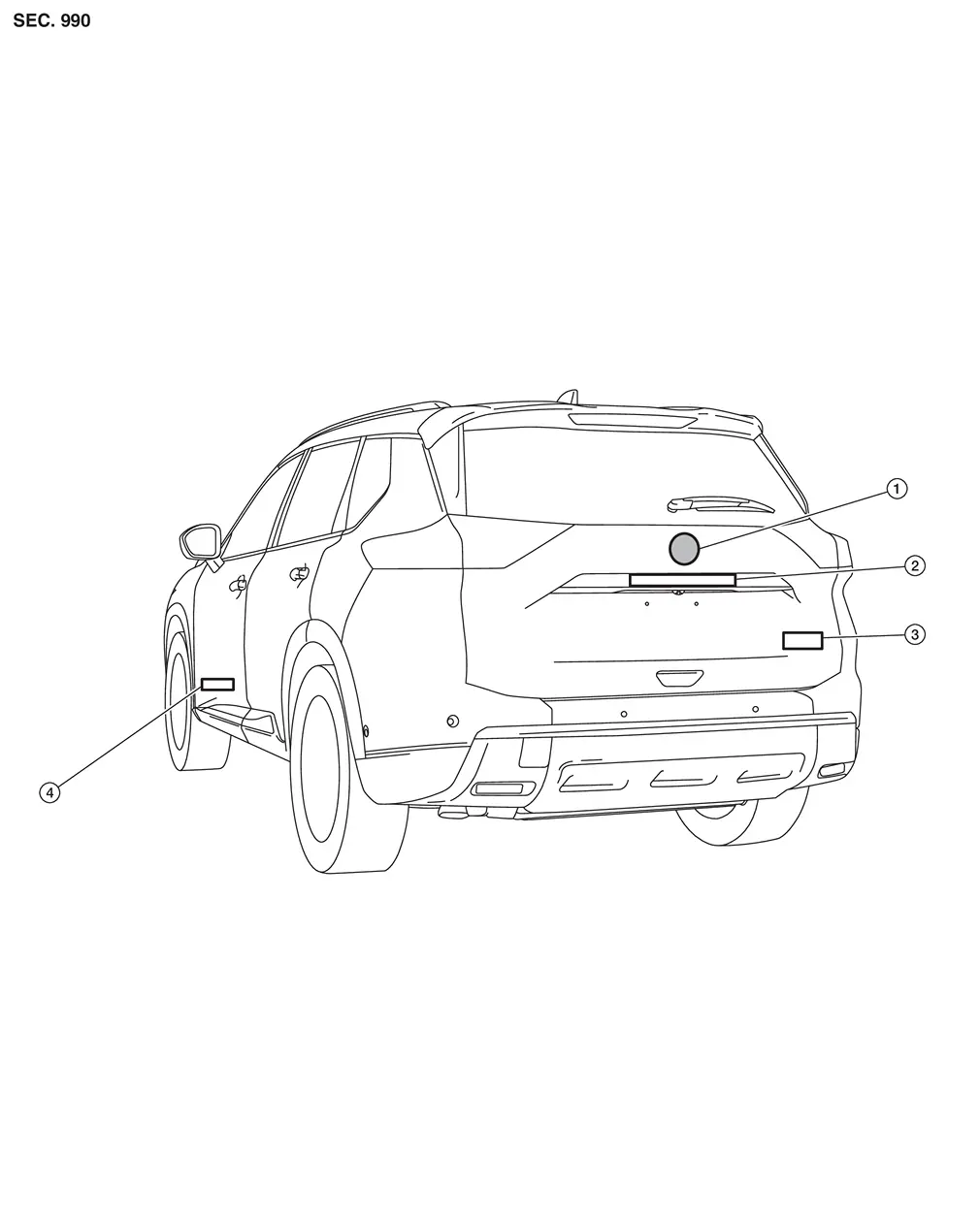
| 1. | Emblem A | 2. | Emblem B | 3. | Emblem C (if equipped) |
| 4. | Emblem D (if equipped) |
Removal and Installation
REMOVAL
Remove emblem from the panel while warming using an industrial dryer
CAUTION:
Remove the panel so as not to damage the paint.
INSTALLATION
CAUTION:
-
Never reuse the emblem which was peeled.
-
Degrease the panel emblem mount.
-
If paint bumps, dust, etc., adhere to the emblem mounting surface, it may cause a defective appearance.
 NOTE:
NOTE:
-
Refer to the figure below for the emblem mounting position.
-
For the left and right center position of emblem A, measure between the left and right ends of the back door assembly, put out the center of the back door assembly, and attach emblem A.
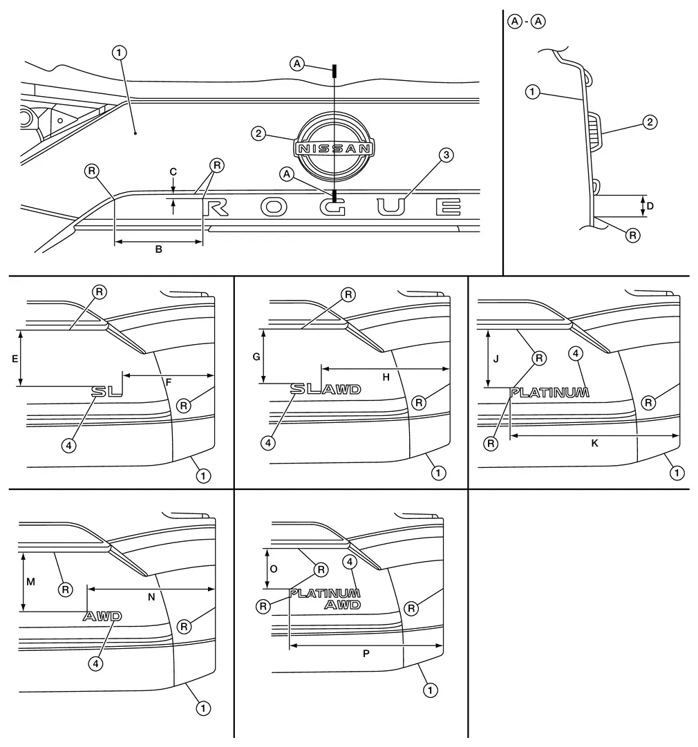
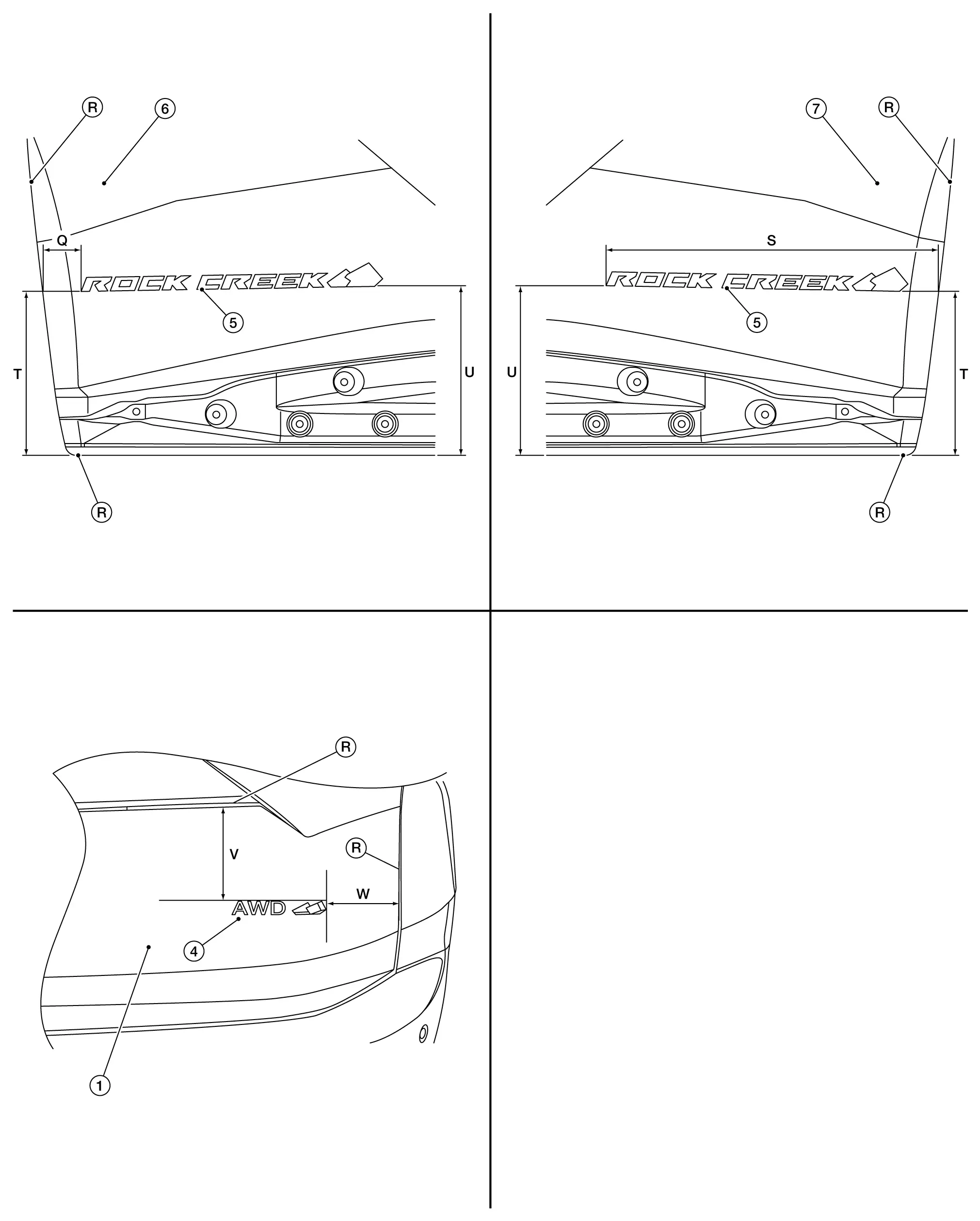
1. Back door panel 2. Emblem A 3. Emblem B 4. Emblem C (if equipped) 5. Emblem D (if equipped) 6. Driver door assembly 7. Passenger door assembly 
R end
B : 141.4 mm (5.567 in) C : 7.7 mm (0.303 in) D : 17.4 mm (0.685 in) E : 135.8 mm (5.346 in) F : 223.1 mm (8.783 in) G : 135.0 mm (5.315 in) H : 312.3 mm (12.295 in) J : 138.9 mm (5.468 in) K : 398.0 mm (15.669 in) M : 141.0 mm (5.551 in) N : 299.7 mm (11.799 in) O : 109.9 mm (4.327 in) P : 398.9 mm (15.705 in) Q : 38.1 mm (1.50 in) S : 412.7 mm (16.25 in) T : 201.3 mm (7.93 in) U : 209.5 mm (8.25 in) V : 127.0 mm (5.00 in) W : 139.7 mm (5.50 in)
Other materials:
U2248 Can Comm Circuit
DTC Description
DTC DETECTION LOGIC DTC
CONSULT screen terms
(Trouble diagnosis content)
DTC detection condition
U2248
83
CAN comm err (brake control unit)
[CAN comm err (brake control unit)]
Diagnosis condition
Ignition switch ON
Signal (terminal)
CAN communicati ...
Component Parts
Chassis Control System
Without Propilot Assist 2.1
Component Parts Location
A.
View with instrument panel assembly removed
No. Component parts Function
1.
BCM (Body Control Module)
BCM transmits the drive mode select switch to the chassis control module via CAN co ...
Shortcut Menu
When the button is pressed, the "Shortcut Menu" appears on the Nissan Rogue vehicle information display. Turn the scroll dial to highlight an item, then press to select.
The following shortcut options are available:
Change Meter View (if equipped)
Allows the driver to select ...