Nissan Rogue (T33) 2021-Present Service Manual: Component Parts
Chassis Control System
Without Propilot Assist 2.1
Component Parts Location
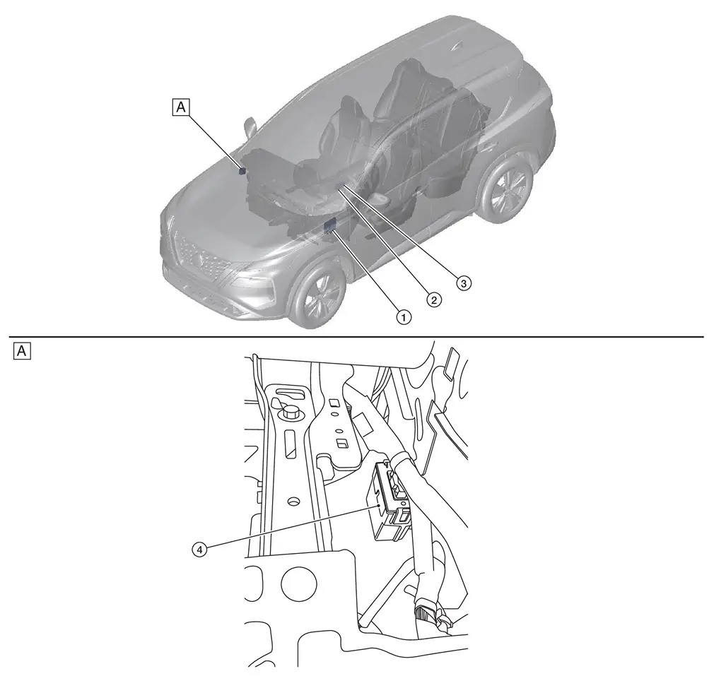
| A. | View with instrument panel assembly removed |
| No. | Component parts | Function |
|---|---|---|
| 1. | BCM (Body Control Module) |
BCM transmits the drive mode select switch to the chassis control module via CAN communication. Refer to Component Parts Location for detailed component location. |
| 2. | Parking brake switch (automatic brake hold switch) |
Refer to Parking Brake Switch (Automatic Brake Hold Switch). Refer to Component Parts Location for detailed component location. |
| 3. | Drive mode select switch |
Refer to Drive Mode Select Switch. Refer to Component Parts Location for detailed component location. |
| 4. | Chassis control module | Refer to Chassis Control Module. |
With Propilot Assist 2.1
Component Parts Location
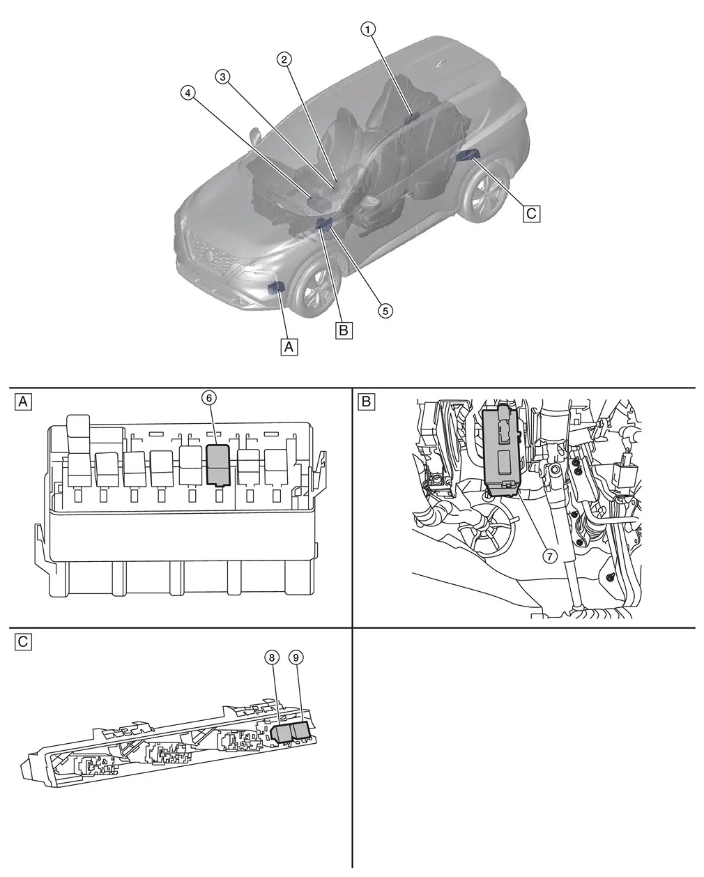
| A. | Behind front bumper fascia | B. | View with instrument lower panel LH removed | C. | Left rear luggage area |
| No. | Component parts | Function |
|---|---|---|
| 1. | Power network separate relay | Refer to Component Parts Location for detailed component location. |
| 2. | Drive mode select switch |
Refer to Drive Mode Select Switch. Refer to Component Parts Location for detailed component location. |
| 3. | Parking brake switch (automatic brake hold switch) |
Refer to Parking Brake Switch (Automatic Brake Hold Switch). Refer to Component Parts Location for detailed component location. |
| 4. | 12V Sub battery (lithium ion battery) | Refer to Component Parts Location for detailed component location. |
| 5. | BCM (Body Control Module) |
BCM transmits the drive mode select switch to the chassis control module via CAN communication. Refer to Component Parts Location for detailed component location. |
| 6. | Shift actuator relay and stop lamp relay (stop lamp relay) |
|
| 7. | Chassis control module | Refer to Chassis Control Module. |
| 8. | Ignition relay-4 |
|
| 9. | Accessory relay-1 |
Chassis Control Module
Chassis control module controls the following systems based on the signals from each sensor, each switch, and each control unit.
-
Intelligent trace control function
-
Active ride control function
-
Automatic brake hold function
-
Drive mode selector function
Other materials:
P026b Injection Timing
DTC Description
DTC DETECTION LOGIC DTC
CONSULT screen terms
(Trouble diagnosis content)
DTC detection condition
P026B
00
Injection timing
Diagnosis condition
—
Signal
—
Threshold
ECM does not control fuel injection timing properly when engine is running ...
Removal and Installation. Rear Door
Exploded View
Rear door panel
Grommet
Rear door striker
TORX bolt
Rear door check link
Rear door hinge (lower)
Rear door hinge (upper)
Rear door weather-strip
Double-sided tape [t: 1.2 mm (0.047 in)]
Double-sided tape [t: 0.8 mm (0.031 in)]
&n ...
Symptom Diagnosis. Panic Alarm Function Does Not Operate
Description
Panic alarm does not operate when press the PANIC ALARM button of Intelligent Key.
Diagnosis Procedure
CHECK INTELLIGENT KEY SYSTEM (REMOTE KEYLESS ENTRY FUNCTION)
Press the LOCK button of Intelligent Key.
Are all doors LOCKED?
YES>>
GO TO 2.
NO>>
Check Intelligent ...