Nissan Rogue (T33) 2021-Present Service Manual: System
System Description
-
Chassis control to integrally control the driving system was adopted.
-
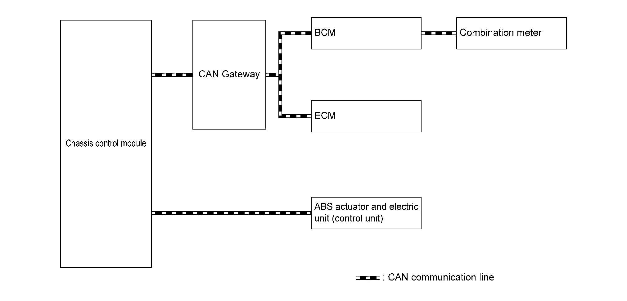
Chassis control module inputs the necessary information for control from CAN communication and each switch and integrally controls each system. Refer to the following table for systems controlled and input output signals.
| Function | Reference page | |
|---|---|---|
| Intelligent trace control function | System Description | |
| Active ride control function* | System Description | |
| Automatic brake hold function | System Description | |
| Drive mode selector function | System Description (2WD Models), System Description (AWD Models) | |
*: If equipped
SYSTEM DIAGRAM
 NOTE:
NOTE:
AWD control unit is applied to AWD models.
Without ProPILOT Assist 2.1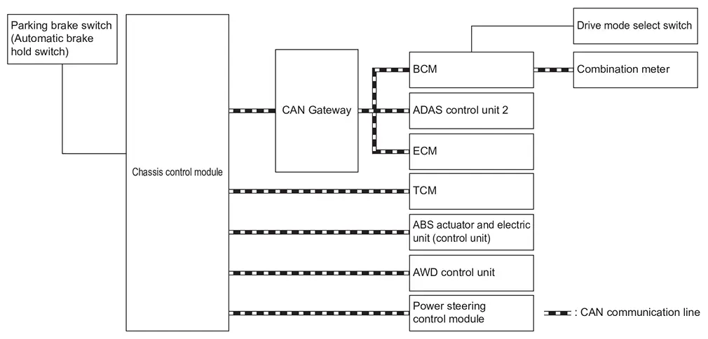
With ProPILOT Assist 2.1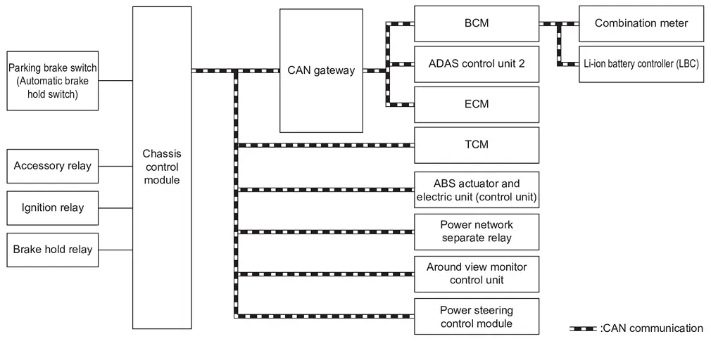
INPUT SIGNAL AND OUTPUT SIGNAL
Major signal transmission between each unit via communication lines is shown in the following table.
| Component parts | Signal description |
|---|---|
| ECM |
Mainly transmits the following signals to chassis control module via CAN communication.
Mainly receives the following signals from chassis control module via CAN communication.
|
| ABS actuator and electric unit (control unit) |
Mainly transmits the following signals to chassis control module via CAN communication.
Mainly receives the following signals from chassis control module via CAN communication.
|
| BCM |
Mainly transmits the following signals to chassis control module via CAN communication.
|
| TCM |
Mainly transmits the following signals to chassis control module via CAN communication.
Mainly receives the following signals from chassis control module via CAN communication.
|
| Combination meter |
Mainly transmits the following signals to chassis control module via CAN communication.
Mainly receives the following signals from chassis control module via CAN communication.
|
| AWD control unit*2 |
Mainly transmits the following signals to chassis control module via CAN communication.
Mainly receives the following signals from chassis control module via CAN communication.
|
| ADAS control unit 2 |
Mainly transmits the following signals to chassis control module via CAN communication.
Mainly receives the following signals from chassis control module via CAN communication.
|
| Power steering control module |
Mainly receives the following signals from chassis control module via CAN communication.
Mainly transmits the following signals to chassis control module via CAN communication.
|
| Li-ion battery controller (LBC)*1 |
Mainly transmits the following signals to chassis control module via CAN communication.
|
| Power network separate relay*1 |
Mainly transmits the following signals to chassis control module via CAN communication.
Mainly receives the following signals from chassis control module via CAN communication.
|
| Around view monitor control unit*1 |
Mainly transmits the following signals to chassis control module via CAN communication.
|
*1: With ProPILOT Assist 2.1
*2: AWD models
MAC (MESSAGE AUTHENTICATION CODE)
MAC (Message Authentication Code) is a function that prevents unauthorized communication from other than the ECU with MAC function by secure authentication communication. Chassis control module can write a MAC key required for communication between the ECUs and perform MAC diagnosis.
Fail-safe
When a malfunction occurs in the chassis control module, the master warning lamp turns ON and an interrupt is displayed on the information display of the combination meter.
| DTC | Fail-safe condition |
|---|---|
| C1B80-54 |
The following functions are suspended.
|
| C1B81-55 | |
| C1B8B-82 | Normal control |
| C1B8C-82 | |
| C1B8D-82 | |
| C1B8F-82 |
The following functions are suspended.
|
| C1B90-82 | Normal control |
| C1B92-82 |
The following functions are suspended.
|
| C1B93-82 |
The following functions are suspended.
|
| C1B94-82 |
The following functions are suspended.
|
| C1B96-82 |
The following functions are suspended.
|
| C1B97-82 |
The following functions are suspended.
|
| C1BB4-44 |
The following functions are suspended.
|
| C1BB4-45 |
The following functions are suspended.*1
|
| C1BB4-46 | |
| C1BB4-49 |
The following functions are suspended.
|
| U0076-00 |
The following functions are suspended.*1
|
| U007A-00 | |
| U1327-52 | |
| U1327-54 | |
| U2118-87 | Normal control |
| U2140-57 | - |
| U2140-83 |
The following functions are suspended.
|
| U2140-87 | |
| U2141-57 | Normal control |
| U2143-83 |
The following functions are suspended.
|
| U2143-87 | |
| U214F-57 | - |
| U214F-83 |
The following functions are suspended.
|
| U214F-87 |
The following functions are suspended.
|
| U2152-57 | - |
| U2152-83 | Normal control |
| U2152-87 |
The following functions are suspended.*3
|
| U2154-87 | |
| U215B-83 |
The following functions are suspended.
|
| U215B-87 | |
| U2165-57 | - |
| U218B-83 | Normal control |
| U218B-87 | |
| U2248-83 |
The following functions are suspended.
|
| U2248-87 | |
| U2359-83 | Normal control |
| U2359-87 | |
| U2448-87 |
The following functions are suspended.
|
| U24A6-83 | Normal control |
| U24A6-87 | |
| U2541-83 |
The following functions are suspended.
|
| U2541-87 | |
| U2675-83 | Normal control |
| U2675-87 | |
| U2A03-88 |
The following functions are suspended.*1
|
| U2A0A-88 | |
| U2A0B-88 | |
| U2A0E-88 | |
| U2A16-88 | |
| U2A17-88 | |
| U2E52-57 | - |
| U2E52-83 | Normal control |
| U2E52-87 | |
| U2E65-57 | - |
| U2E75-57 |
*1: Depends on the DTC detection status
*2: With Telematics System
*3: Without Telematics System
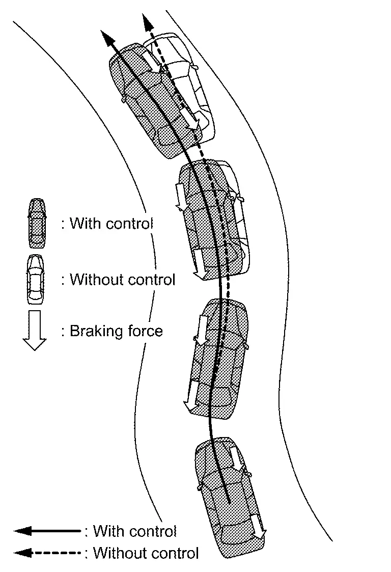
Intelligent Trace Control Function
System Description
-
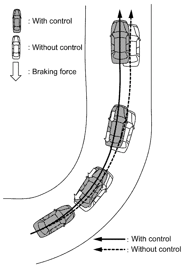
This function senses driving based on the driver’s steering and acceleration/braking patterns, and controls brake pressure at individual wheels to aid tracing at corners and help smooth Nissan Ariya vehicle response.
-
Amount of brake control is changed based on drive mode select switch.
-
When the VDC function is turned OFF, intelligent trace control function is also turned OFF.
-
When intelligent trace control function is not functioning properly, the master warning lamp illuminates, and Warning message will also appear on information display.
NOTE:
-
Intelligent trace control function is not always activated in any driving conditions.
-
When the intelligent trace control function is activated, the driver may feel some vibration on the brake pedal, hear operating sound, or have feel of the deceleration. This is not a malfunction because it is caused by intelligent trace control function that is normally operated.
-
OPERATION CHARACTERISTICS
-
Transient steering input - Reduces lag of yaw rate against steering operation.
-
The brake is controlled according to the steering operation condition of the driver and the cornering condition of the Nissan Ariya vehicle.
-
-
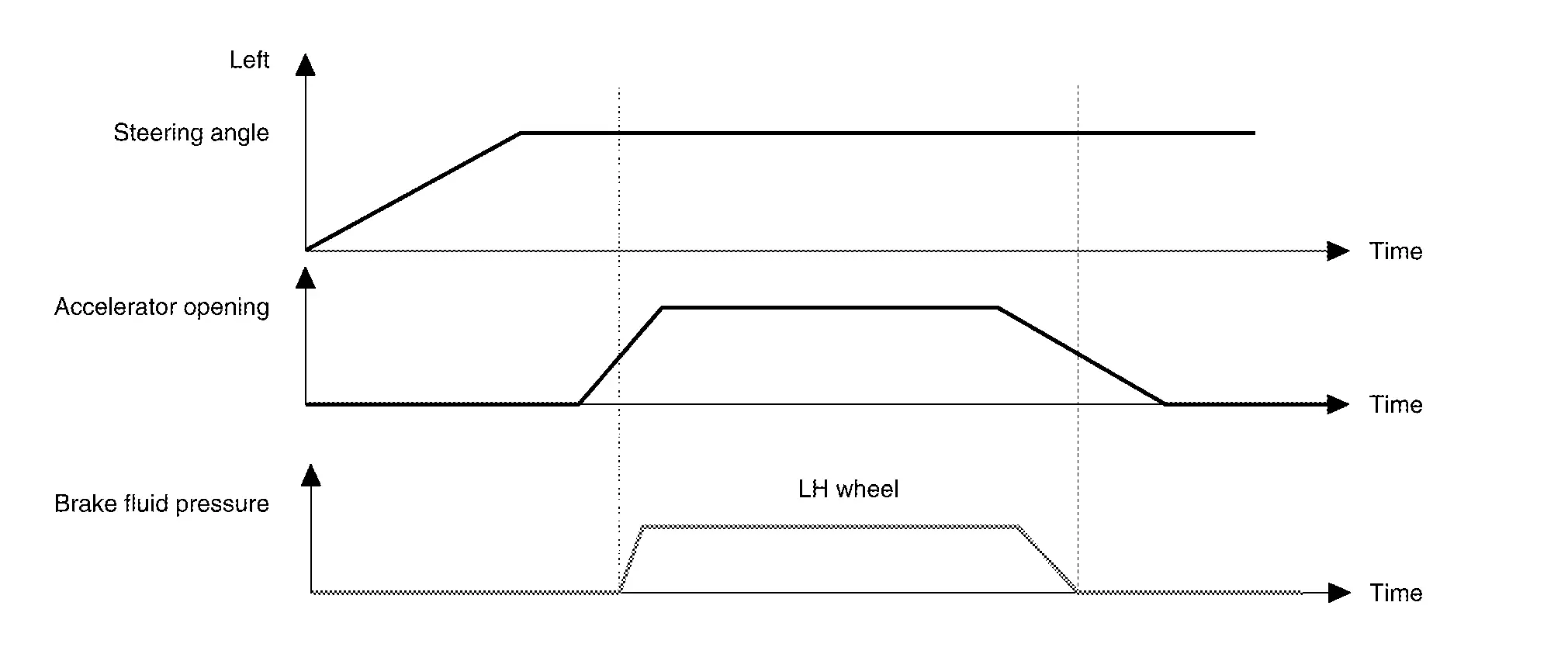
Acceleration at corners - Restrains understeer by applying the necessary amount of brake pressure to the inner wheels.
-
The brake is controlled according to the steering operation condition of the driver and the cornering condition of the Nissan Ariya vehicle.
-
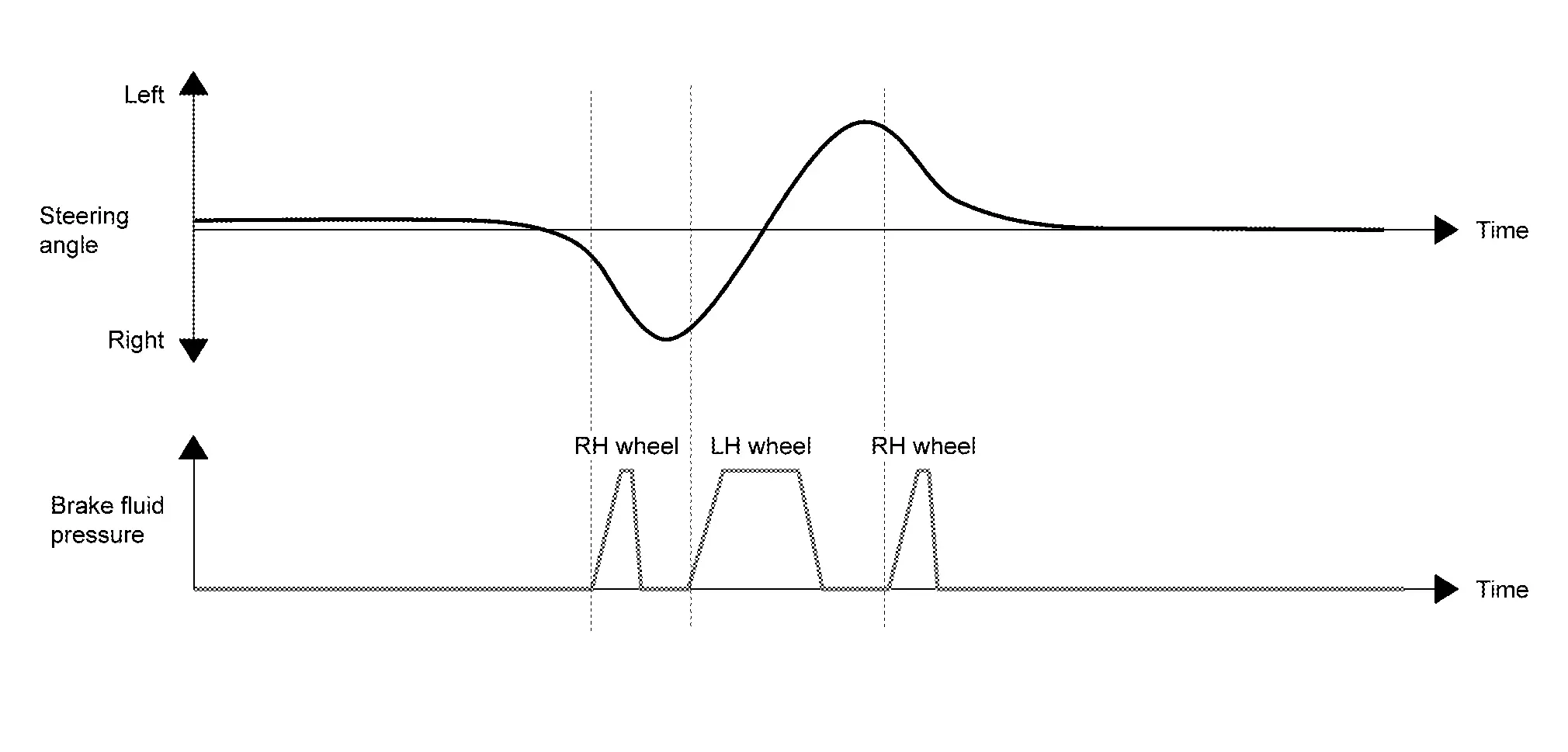
-
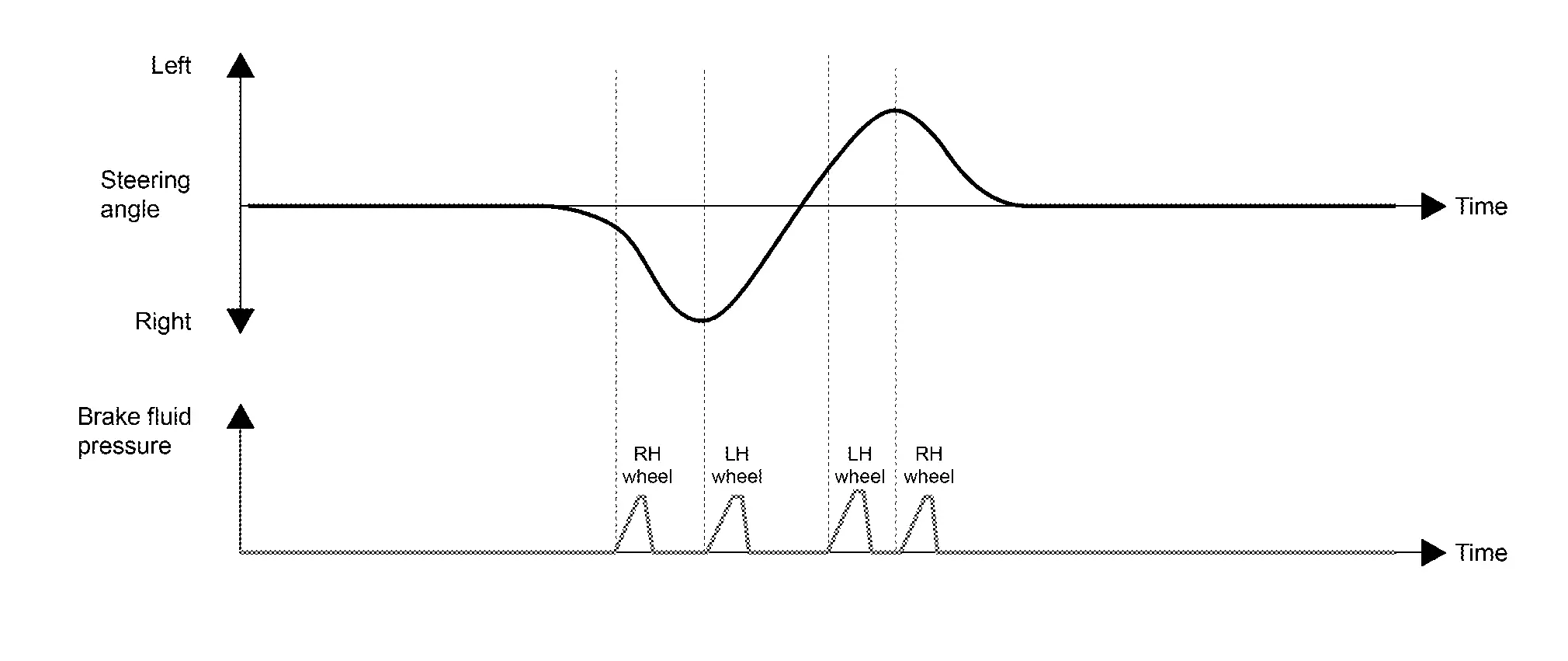
Quick lane change - achieves stable Nissan Ariya vehicle behavior at quick steering operation by applying the necessary amount of brake pressure to the appropriate wheels.

-
The brake is controlled according to the steering operation condition of the driver and the cornering condition of the Nissan Ariya vehicle.
-
SYSTEM DIAGRAM
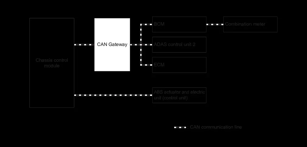
INPUT SIGNAL AND OUTPUT SIGNAL
Major signal transmission between each unit via communication lines is shown in the following table.
| Component parts | Signal description |
|---|---|
| ECM |
Mainly transmits the following signals to chassis control module via CAN communication.
|
| ABS actuator and electric unit (control unit) |
Mainly transmits the following signals to chassis control module via CAN communication.
Mainly receives the following signals from chassis control module via CAN communication.
|
| Combination meter |
Mainly receives the following signals from chassis control module via CAN communication.
|
| ADAS control unit 2 |
Mainly transmits the following signals to chassis control module via CAN communication.
|
Active Ride Control Function (if Equipped)
System Description
-
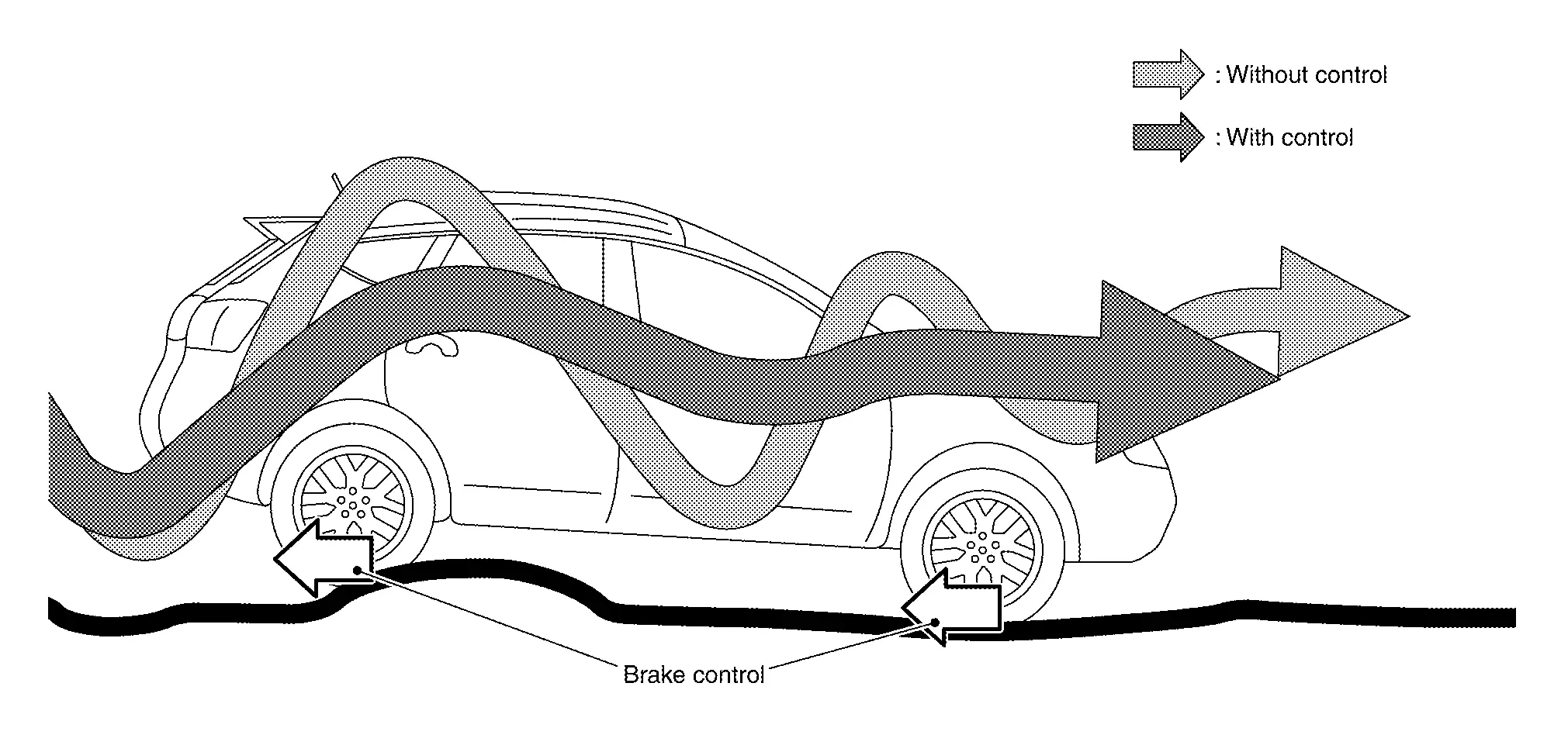
Active ride control function senses upper body motion and controls four wheel brake pressure. This will enhance ride comfort in effort to restrain uncomfortable upper body movement when passing over undulated road surfaces.
-
When the VDC function is turned OFF, active ride control function is also turned OFF.
-
When active ride control function is not functioning properly, the master warning lamp illuminates, and Warning message will also appear on information display.
NOTE:
-
Active ride control function is not always activated in any driving conditions.
-
When the active ride control function is activated, the driver may feel some vibration on the brake pedal, hear operating sound, or have feel of the deceleration. This is not a malfunction because it is caused by active ride control function that is normally operated.
-
BRAKING CONTROL
-
Brake control - Enhances ride comfort by restraining upper body movement with small amount of brake control when driving on bumpy roads.
SYSTEM DIAGRAM
INPUT SIGNAL AND OUTPUT SIGNAL
Major signal transmission between each unit via communication lines is shown in the following table.
| Component parts | Signal description |
|---|---|
| ECM |
Mainly transmits the following signals to chassis control module via CAN communication.
|
| ABS actuator and electric unit (control unit) |
Mainly transmits the following signals to chassis control module via CAN communication.
Mainly receives the following signals from chassis control module via CAN communication.
|
| Combination meter |
Mainly receives the following signals from chassis control module via CAN communication.
|
Information Display (combination Meter)
Chassis Control Warning
DESIGN/PURPOSE
The warning message is displayed on the information display when “Chassis Control” detected the system malfunction.
Warning Message
| Design | Warning Message |
|---|---|
| — |
Chassis Control System Error See Owner’s Manual |
SYNCHRONIZATION WITH MASTER WARNING LAMP
Applicable
-
Full TFT meter: Refer to Master Warning Lamp.
-
7 inch information display: Refer to Master Warning Lamp.
SYNCHRONIZATION WITH WARNING CHIME
Not applicable
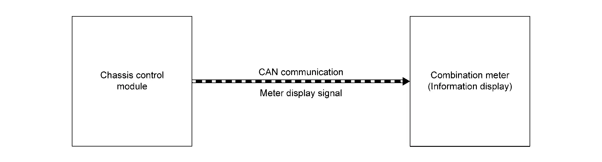
SYSTEM DIAGRAM
SIGNAL PATH
-
The chassis control module transmits the meter display signal to the combination meter via CAN communication.
-
The combination meter shows the chassis control warning on the information display, according to the signal.
WARNING MESSAGE DISPLAY CONDITION
When all of the following conditions are satisfied
-
Ignition switch is ON
-
Chassis control system malfunction is detected. Refer to DTC Index (Without telematics system) or DTC Index (With telematics system).
Other materials:
Entretien général
Informations de base
Lors de l’utilisation normale de votre Nissan Rogue, les opérations d’entretien général doivent être réalisées régulièrement et avec rigueur, conformément aux instructions décrites dans cette section. Toute apparition de bruits anormaux, de vibrations inhabituelle ...
P0420 Three Way Catalyst Function
DTC Description
The ECM monitors the switching frequency ratio of air fuel ratio (A/F) sensor 1 and heated oxygen sensor 2.A
three way catalyst (manifold) with high oxygen storage capacity will
indicate a low switching frequency of heated oxygen sensor 2. As oxygen
storage capacity decreases, ...
Étiquette des pneus
Exemple
Informations de base
La législation fédérale impose aux fabricants de pneus d’apposer sur le flanc de chaque pneu des informations normalisées et clairement lisibles. Ces marquages, présents sur les pneus du Nissan Rogue, permettent d’identifier les caractéristiques essenti ...