Nissan Rogue (T33) 2021-Present Service Manual: Removal and Installation :: Battery Tray
Exploded View
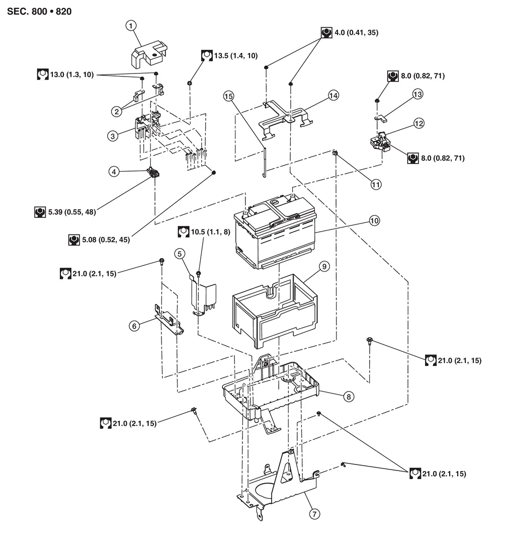
| 1. | Battery positive terminal cover | 2. | Positive cable | 3. | Battery terminal with fusible link |
| 4. | Battery positive terminal | 5. | Battery protector | 6. | Battery mounting bracket |
| 7. | Battery tray 1 | 8. | Battery tray 2 | 9. | Battery cover |
| 10. | 12V battery | 11. | Battery fix rod clip | 12. | 12V battery current sensor |
| 13. | Negative cable | 14. | Battery fix frame | 15. | Battery fix rod |
| : Nissan Ariya Vehicle front |
Removal and Installation
REMOVAL
Remove 12V battery. Refer to Removal and Installation.
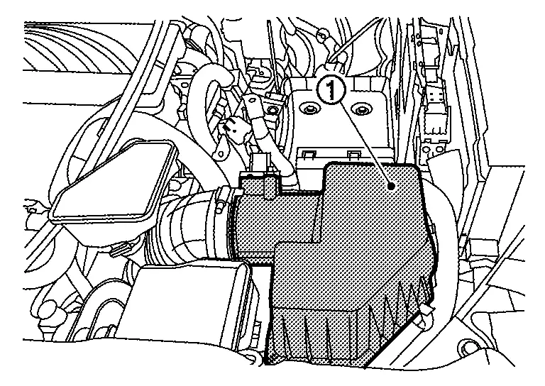
Remove air cleaner cover  .
.
Press the pawl of engine room harness and pull up engine room harness in the direction of the arrow.
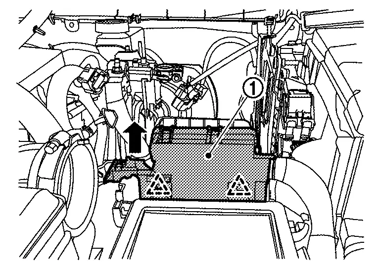
 |
: Pawl |
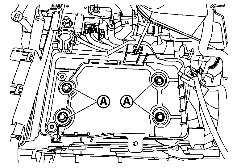
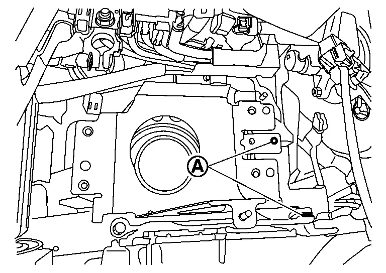
Remove battery mounting bracket mounting bolts  , and then remove the battery mounting bracket from the battery tray 2.
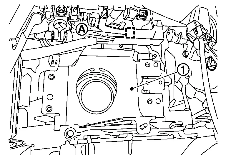
Remove battery tray 2 mounting bolts from battery tray 2.
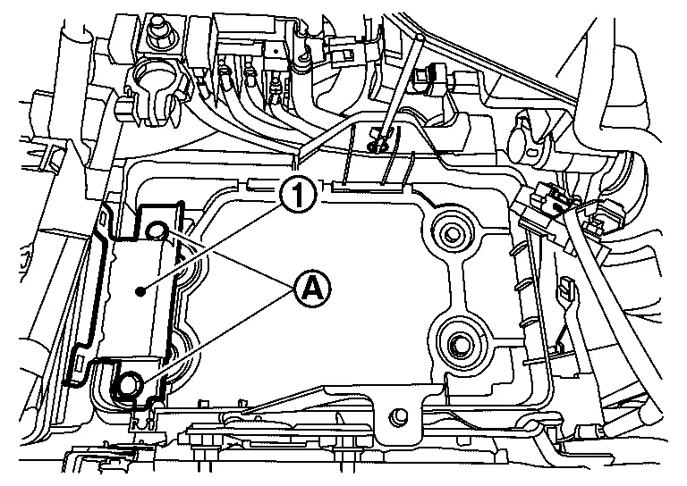
Disconnect ECM connector  from ECM.
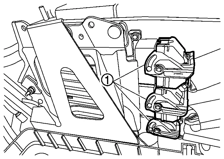
Remove battery tray 2 mounting bolt , and then remove the battery tray 2 from the battery tray 1.
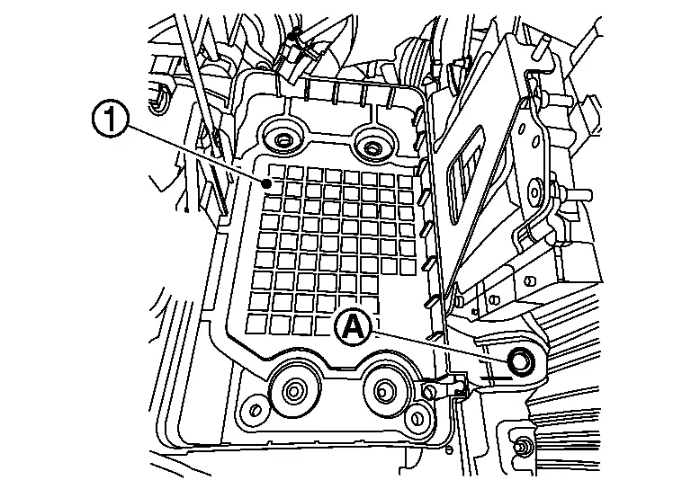
Remove battery fix rod  from battery tray 2 .
Remove battery tray 1 mounting bolts from battery tray 1.
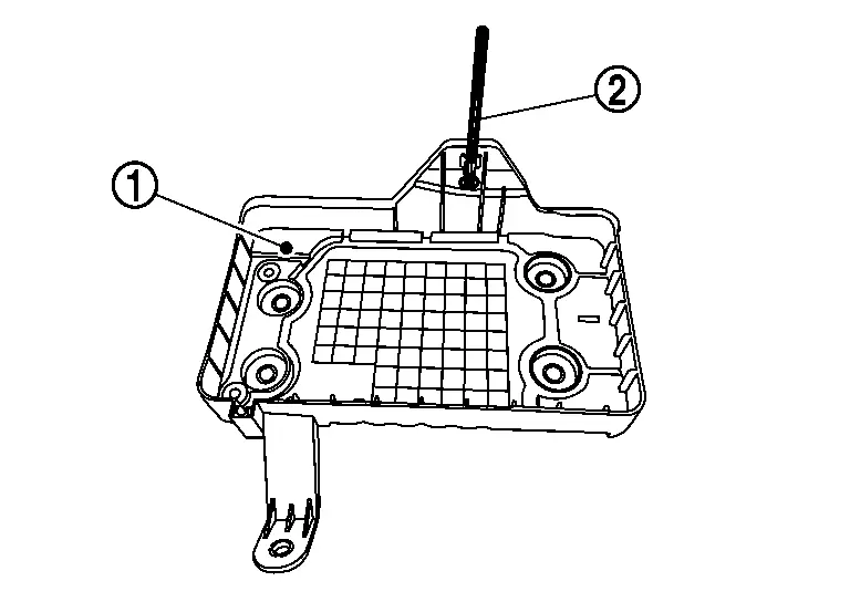
Remove harness clip , and then remove the battery tray 1 from the Nissan Ariya vehicle.
INSTALLATION
Installation is in the reverse order of removal.
CAUTION:
Perform Required Procedure After Battery Disconnection.
Other materials:
B2e49-06 Remote Actuator
DTC Description
DTC DETECTION LOGIC DTC No.
CONSULT screen terms
(Trouble diagnosis content) DTC detection condition
B2E49–06
Remote actuator not activated
(Remote actuator not activated)
Diagnosis condition
When receiving remote command
Signal (terminal)
—
Thresh ...
Service Data and Specifications (sds)
Road Wheel
ALUMINUM WHEEL Item Limit
Runout
Axial runout
Less than 0.3 mm (0.012 in)
Radial runout
Allowable unbalance
Dynamic (At flange)
Less than 5 g (0.17 oz) (one side)
Static (At flange)
Less than 10 g (0.35 oz)
STEEL WHEEL (EMERGENCY) Item Limit
Runo ...
B3a70 Intelligent Battery Sensor
DTC Description
DTC DETECTION LOGIC DTC
CONSULT screen terms
(Trouble diagnosis content)
DTC detection condition
B3A70
00
IBS Battery Temp Sensor Failure (Open Circuit)
[IBS battery temp sensor failure (Open circuit)]
Diagnosis condition
Ignition switch ON
Batte ...