Nissan Rogue (T33) 2021-Present Service Manual: Removal and Installation :: Battery
Exploded View
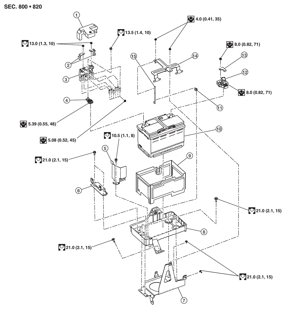
| 1. | Battery positive terminal cover | 2. | Positive cable | 3. | Battery terminal with fusible link |
| 4. | Battery positive terminal | 5. | Battery protector | 6. | Battery mounting bracket |
| 7. | Battery tray 1 | 8. | Battery tray 2 | 9. | Battery cover |
| 10. | 12V battery | 11. | Battery fix rod clip | 12. | 12V battery current sensor |
| 13. | Negative cable | 14. | Battery fix frame | 15. | Battery fix rod |
| : Nissan Ariya Vehicle front |
Removal and Installation
REMOVAL
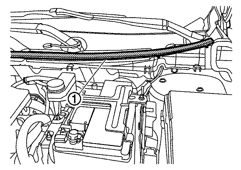
Remove cowl top seal  .
.
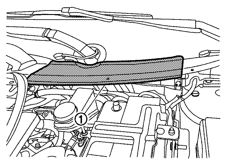
Remove cowl top cover . Refer to Removal and Installation.
Disconnect the 12V battery cable from the negative terminal.
CAUTION:
To prevent damage to the parts, disconnect the 12V battery cable from the negative terminal first.
Disconnect the 12V battery cable from the positive terminal.
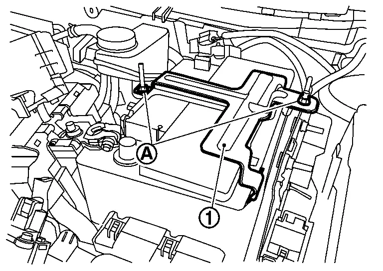
Remove battery fix frame mounting nuts  and battery fix frame .
Remove 12V battery.
INSTALLATION
Installation is in the reverse order of removal.
CAUTION:
To install the 12V battery, carefully read the following instructions.
-
To prevent damage to the parts, connect the 12V battery cable to the positive terminal first.
-
After connecting 12V battery cables, to securely supply 12V battery voltage, ensure that they are tightly clamped to 12V battery terminals for good contact.
-
To securely supply 12V battery voltage, check 12V battery terminal for poor connection caused by corrosion.
Perform Required Procedure After Battery Disconnection.
Other materials:
Operating manual liftgate
To open the liftgate of your Nissan Rogue, unlock it and pull upward to raise the door.
The liftgate can be unlocked by:
pushing the UNLOCK
button on the Intelligent Key twice.
pushing the liftgate request switch (if equipped).
pushing the door handle request switch (if equipped).
To clo ...
B24a0-49 A/c Auto Amp.
DTC Description
DTC DETECTION LOGIC DTC No.
CONSULT screen terms
(Trouble diagnosis content) DTC detection condition
B24A0-49
A/C AUTO AMP.
(Air conditioning automatic amplifier)
Diagnosis condition
Ignition switch ON
Signal (Terminal)
—
Threshold
A malfunction i ...
C1f03-72 Stop Lamp Relay
Without Propilot Assist 2.1
DTC Description
DTC DETECTION LOGIC DTC
CONSULT screen terms
(Trouble diagnosis content) DTC detection condition
C1F03
72
OPERATION SW CIRC
(Operation switch circuit)
Diagnosis condition
When engine is running
When AEB system is ...