Nissan Rogue (T33) 2021-Present Service Manual: Rear View Monitor :: Dtc/circuit Diagnosis
Power Supply and Ground Circuit
Av Control Unit
Diagnosis Procedure
CHECK FUSE
-
Turn ignition switch OFF.
-
Check that the following fuse is not blown (open)
Power source Fuse No. Capacity Battery #25 20 A
Is the fuse blown (open)?
YES>>Replace fuse after repairing the applicable circuit.
NO>>GO TO 2.
CHECK AV CONTROL UNIT BATTERY POWER SUPPLY
-
Turn ignition switch OFF.
-
Disconnect AV control unit harness connector.
-
Check the voltage between AV control unit harness connector and ground.
(+) (ŌłÆ) Voltage AV control unit Connector Terminal M101 19 Ground Battery voltage
Is the inspection result normal?
YES>>GO TO 3.
NO>>Perform trouble diagnosis for battery power supply circuit.
CHECK GROUND CIRCUIT
-
Turn ignition switch OFF.
-
Check the continuity between AV control unit and ground.
(+) (ŌłÆ) Continuity AV control unit Connector Terminal M101 20 Ground Existed
Is the inspection result normal?
YES>>INSPECTION END
NO>>Repair or replace malfunctioning parts.
Camera Power Supply Circuit
Diagnosis Procedure
CHECK CONTINUITY CAMERA POWER SUPPLY CIRCUIT
-
Turn ignition switch OFF.
-
Disconnect AV control unit harness connector and rear view camera harness connector.
-
Check continuity between AV control unit harness connector and rear view camera harness connector.
AV control unit Rear view camera Continuity Connector Terminal Connector Terminal M102 28 D504 2 Existed -
Check continuity between AV control unit harness connector and ground.
AV control unit Ground Continuity Connector Terminal M102 28 Not existed
Is the inspection result normal?
YES>>GO TO 2.
NO>>Repair or replace harness or connector.
CHECK VOLTAGE CAMERA POWER SUPPLY
-
Connect AV control unit connector and rear view camera connector.
-
Turn ignition switch ON.
-
Shift the selector lever to ŌĆ£RŌĆØ position.
-
Check voltage between AV control unit harness connector and ground.
(+) (ŌłÆ) Condition Standard Voltage
(Approx.)AV control unit Connector Terminal M102 28 Ground At camera image is displayed. 5.5 - 6.5 V 6.0 V
Is the inspection result normal?
YES>>Replace rear view camera. Refer to Removal and Installation.
NO>>Replace AV control unit. Refer to .Removal and Installation
Camera Image Signal Circuit
Diagnosis Procedure
CHECK CONTINUITY CAMERA IMAGE SIGNAL CIRCUIT
-
Turn ignition switch OFF.
-
Disconnect AV control unit harness connector and rear view camera harness connector.
-
Check continuity between AV control unit harness connector and rear view camera harness connector.
AV control unit Rear view camera Continuity Connector Terminal Connector Terminal M102 49 D504 1 Existed -
Check continuity between AV control unit harness connector and ground.
AV control unit Ground Continuity Connector Terminal M102 49 Not existed
Is the inspection result normal?
YES>>GO TO 2.
NO>>Repair or replace harness or connector.
CHECK CAMERA IMAGE SIGNAL
-
Connect AV control unit harness connector and rear view camera harness connector.
-
Turn ignition switch ON.
-
Shift the selector lever to ŌĆ£RŌĆØ position.
-
Check signal between AV control unit harness connector and ground.
(+) (ŌłÆ) Condition Standard Reference value AV control unit Connector Terminal M102 49 Ground At camera image is displayed. Input the waveform synchronized with the rear view camera image. 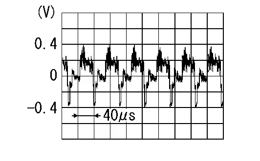
Is the inspection result normal?
YES>>Replace AV control unit. Refer to Removal and Installation.
NO>>Replace rear view camera. Refer to Removal and Installation.
Other materials:
Dtc/circuit Diagnosis. B2001-45 Intelligent Key Unit
DTC Description
DTC DETECTION LOGIC DTC No.
CONSULT screen items
(Trouble diagnosis content) DTC Detection Condition
B2001-45
Intelligent Key unit
(Intelligent Key unit)
Diagnosis condition
Ignition switch ON
Signal (terminal)
ŌĆö
Threshold
Intelligent Key unit is ...
P2128 App Sensor
DTC Description
DTC DETECTION LOGIC DTC
CONSULT screen terms
(Trouble diagnosis content)
DTC detection condition
P2128
00
APP SEN 2/CIRC
(Throttle/Pedal position sensor/switch E circuit high)
Diagnosis condition
Engine running at idle
Signal (terminal)
Accelerator ...
B2231-16 Battery Voltage
DTC Description
DTC DETECTION LOGIC DTC No.
CONSULT screen terms
(Trouble diagnosis content) DTC detected condition
B2231-16
Battery voltage
(Battery voltage)
Diagnosis condition
When ignition switch is ON.
Signal (terminal)
Battery power supply
Threshold
8 V or le ...