Nissan Rogue (T33) 2021-Present Service Manual: Purge Pump
Exploded View
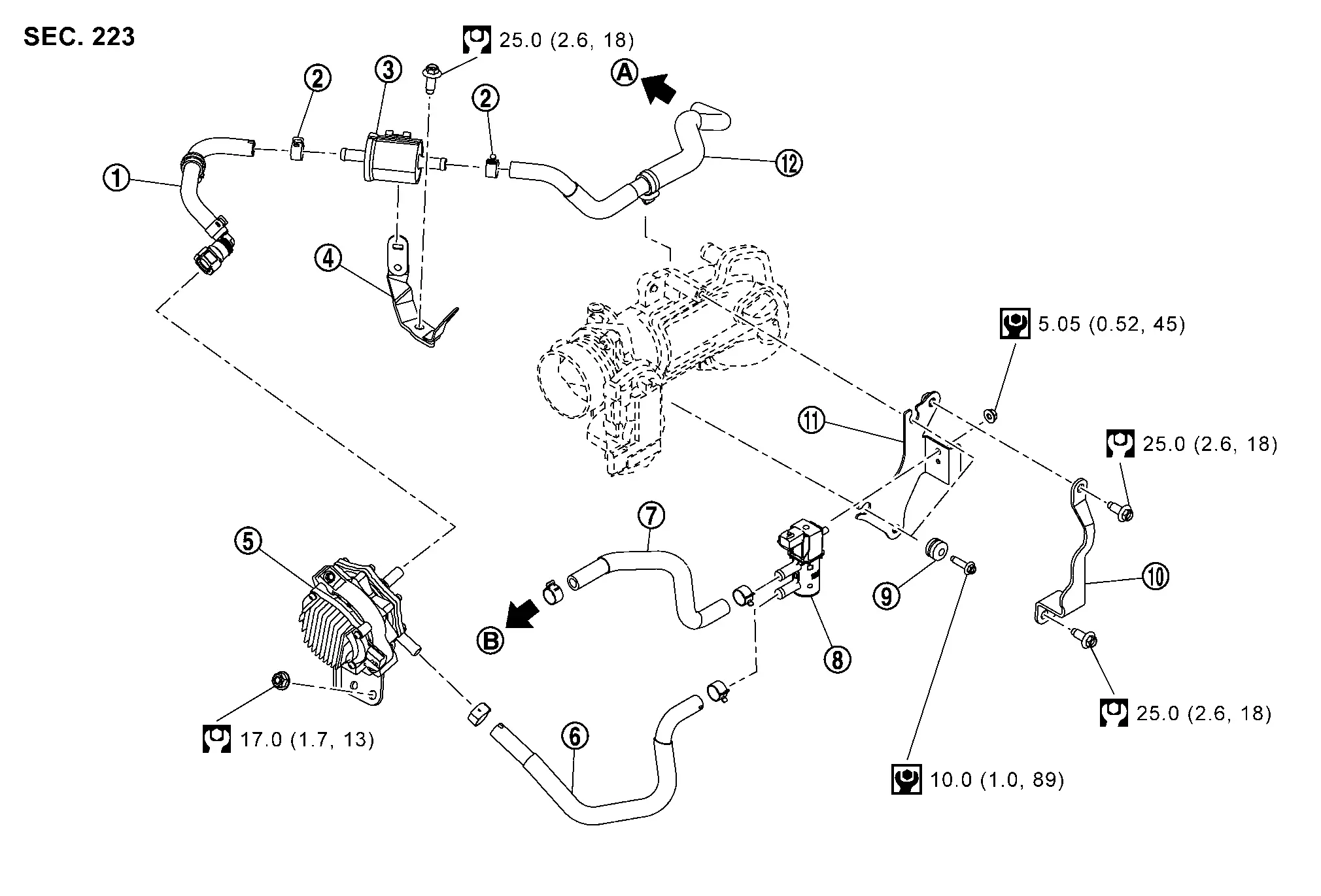
| 1. | Resonator hose 1 | 2. | Clamp | 3. | Resonator |
| 4. | Resonator bracket | 5. | Purge pump | 6. | Purge control valve hose 1 |
| 7. | Purge control valve hose 2 | 8. | Purge control valve | 9. | Mounting rubber |
| 10. | Purge control valve bracket 2 | 11. | Purge control valve bracket 1 | 12. | Resonator hose 2 |
| A | To EVAP canister. Refer to Hydraulic Layout. | B | To air duct. Refer to Exploded View. | — | — |
 |
: N·m (kg-m, ft-lb) | ||||
 |
: N·m (kg-m, in-lb) | ||||
Removal and Installation
REMOVAL
Purge Pump Assembly
Remove engine cover. Refer to Removal and Installation.
Remove resonator. Refer to Removal and Installation.
Remove air duct. Refer to Removal and Installation.
Disconnect the purge pump harness connector  , resonator hose 1
  and purge control valve hose 1
  .
.
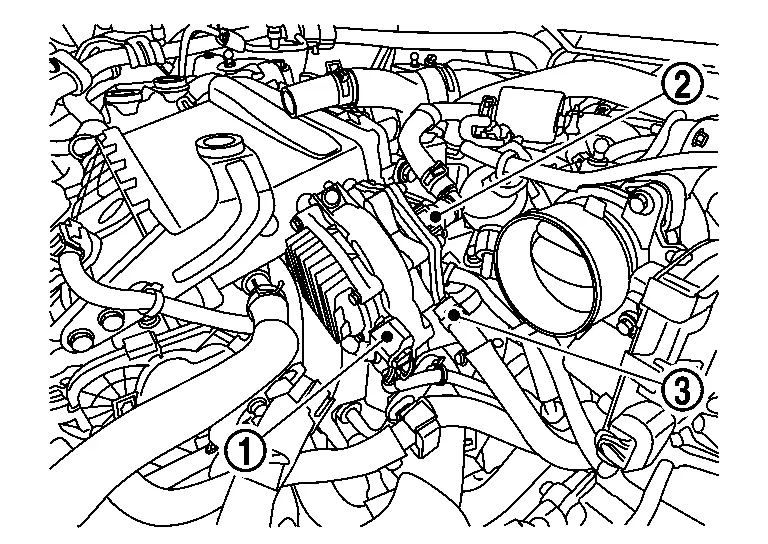
Loosen the purge pump nuts  .
.
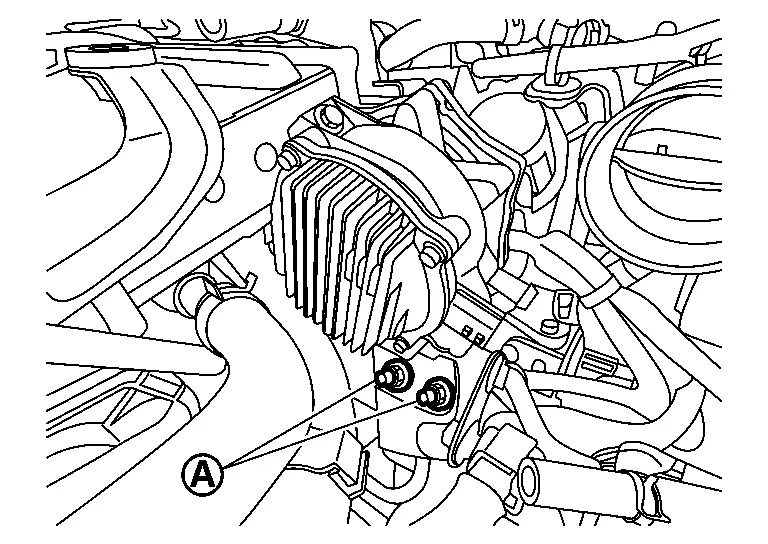
Remove the purge pump.
Purge Control Valve
Remove engine cover. Refer to Removal and Installation.
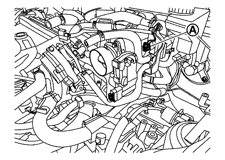
Remove the EVAP canister purge volume control solenoid valve harness connector .
Disconnect purge control valve hose 1 and purge control valve hose 2 from purge control valve.
Loosen purge control valve nut and then remove purge control valve.
Remove purge control valve bracket 1 and purge control bracket 2 if necessary.
Resonator
Remove engine cover.
Disconnect resonator hose 1 and resonator hose 2 from resonator.
Loosen resonator nut and then resonator.
INSTALLATION
Install in the reverse order of removal.
Other materials:
P0261 Fuel Injector (cylinder 1)
DTC Description
DTC DETECTION LOGIC DTC
CONSULT screen terms
(Trouble diagnosis content)
DTC detection condition
P0261
00
CYL1 INJECTOR
(Cylinder 1 Injector A Circuit Low)
Diagnosis condition
—
Signal (terminal)
—
Threshold
Direct injector driver unit ...
Symptom Diagnosis. Engine Can Not Start
Description
Engine does not start when push-button ignition switch is pressed.SYMPTOM TABLE (BOTH INTELLIGENT KEYS HAVE THE SAME SYMPTOMS) Door lock operation (remote keyless entry)
Door lock operation (request switch of front/rear/back door) or
trunk/back door open operation (opener switch of ...
P1c90-49 Sub Starter & Generator
DTC Description
DTC DETECTION LOGIC DTC No. CONSULT screen terms (Trouble diagnosis content) DTC detection condition
P1C90-49
Sub starter & generator
(Sub starter & generator)
Diagnosis condition
Engine running at idle
Signal (terminal)
-
Threshold
Sub starte ...